1
User Manual
Industrial Robot Simulation Software
Version 1.4.0 for Windows XP and Windows Vista
Simtech Systems Inc.
Version 2008-07-23
CONTENTS
1.INTRODUCTION.......................................................................................................5
Overview....................................................................................................................5
Installation and Licensing...........................................................................................6
New Installation......................................................................................................6
Configuring FTP access..........................................................................................8
64 bit installations..................................................................................................9
2.User interface.............................................................................................................10
Toolbars....................................................................................................................10
Top Toolbar..........................................................................................................10
Righthand Toolbar................................................................................................11
Stages Toolbar......................................................................................................12
Animation Speed Toolbar.....................................................................................12
Menus.......................................................................................................................13
File........................................................................................................................13
View.....................................................................................................................13
Model....................................................................................................................14
Help......................................................................................................................15
Supervisor State........................................................................................................15
3.Visualization..............................................................................................................17
Moving, Zooming and Rotating The View..............................................................17
Selecting Objects......................................................................................................17
Clipping Planes.........................................................................................................17
Floor.........................................................................................................................18
Setting Floor Level...............................................................................................18
Hiding Floor.........................................................................................................18
Coordinate Systems..................................................................................................18
Global Coordinate System....................................................................................18
Robot Coordinate System.....................................................................................18
Workpiece Coordinate System.............................................................................18
Path Coordinate System.......................................................................................18
Tool Coordinate System.......................................................................................19
Path Normals............................................................................................................19
Hiding and Showing Objects....................................................................................19
Tweaking Colors......................................................................................................19
Wireframe / Flat / Shaded Visualization..................................................................19
Capturing Pictures and Animations..........................................................................20
4.Managing Robot Cell Layout....................................................................................21
User Manual: Conifer Rob 1.4
2
Selecting Robot Model.............................................................................................21
Managing Tool Containers Library..........................................................................21
Creating New Tool Containers.............................................................................21
Deleting Tool Containers.....................................................................................23
Modifying Tool Containers..................................................................................23
Setting Default Tool Containers...........................................................................24
Managing Tools Library...........................................................................................24
Creating New Tools..............................................................................................24
Deleting Tools......................................................................................................26
Modifying Tools...................................................................................................26
Setting Default Tools............................................................................................26
Workpiece Positioning.............................................................................................26
Robot Position..........................................................................................................27
Changing Robot Position......................................................................................27
Default Robot Position.........................................................................................28
Setting Robot Home Position...............................................................................28
Managing Obstacles.................................................................................................28
Creating New Obstacles.......................................................................................28
Deleting Obstacles................................................................................................29
Moving Obstacles.................................................................................................29
Setting Default Obstacles.....................................................................................29
5.Path Setup..................................................................................................................30
Selecting Workpiece Geometry................................................................................30
Selecting Tool Containers........................................................................................30
Attaching Tool Container To Robot.....................................................................31
Removing Tool Container From Robot................................................................31
Selecting Default Tool Containers.......................................................................31
Selecting Tool...........................................................................................................31
Attaching Tool......................................................................................................31
Selecting Default Tool..........................................................................................32
Reading APT File.....................................................................................................32
Path Positioning........................................................................................................33
Robot Animation......................................................................................................33
6.Path Optimization......................................................................................................34
Path Optimization Settings.......................................................................................34
Robot Velocity Settings............................................................................................36
Path Optimization.....................................................................................................36
Manual Path Manipulation.......................................................................................37
Viewing Path Stages.............................................................................................37
Creating New Path Stages....................................................................................37
User Manual: Conifer Rob 1.4
3
Deleting Path Stages.............................................................................................39
Modifying Path Stages..........................................................................................39
7.Collision Detection and Avoidance...........................................................................40
Collision Detection...................................................................................................40
Collision Avoidance.................................................................................................40
8.Exporting Results......................................................................................................41
Exporting APT.........................................................................................................41
Generating Robot Program.......................................................................................41
Uploading Robot Program to Robot.........................................................................41
9.Batch Runs.................................................................................................................42
APPENDIX A: Robot Program Templates..................................................................43
How robot program generation works?....................................................................43
Templates.................................................................................................................43
Variables...................................................................................................................43
GLOBAL scope....................................................................................................44
MODULE scope...................................................................................................45
JOINTS scope.......................................................................................................46
PATH scope..........................................................................................................46
COMMAND scope...............................................................................................46
MOVEL scope......................................................................................................47
Template Language Specification............................................................................48
User Manual: Conifer Rob 1.4
4
1. INTRODUCTION
Overview
Conifer Rob is a precision tool that fills the process gap between machining path
generation system (such as a CAD system) and the industrial robot running the
machining program. With the help of Conifer Rob one can quickly and safely convert
and move the machining program in *.apt format into the robot for execution.
With the help of Conifer Rob the positioning of the workpiece can be easily designed.
Reachability analysis allows identifying problems in the positioning and ensuring that
selected positioning a functioning one. Conifer Rob converts the imported machining
path into a robot program and optimizes the program for optimum accuracy and
reachability. Conifer Rob also supports doing manual corrections to the machining
path. Finally, the animation and collision detection features in Conifer Rob support
checking the robot program for safety before pushing the robot program into
execution.
Conifer Rob can help you in:
– Converting machining path into a robot program
– Optimizing robot robot program
– Designing the positioning of the workpiece in the robot cell
– Ensuring safety of the generated robot program
– Correcting problems in generated robot program
User Manual: Conifer Rob 1.4
5
Installation and Licensing
New Installation
Prerequisites
To successfully install Conifer Rob you need:
1) PC with at least 512MB of RAM and 10GB of free disk space. 1GB of RAM
and 30GB of free disk space is recommended.
2) Windows XP 32bit or Windows Vista (32bit or 64bit)
3) Display driver with some hardware 3D acceleration (most display adapters
these days have)
4) Conifer Rob Installer executable
5) Valid ethernet address (MAC) bound license file for Conifer Rob or
alternatively a USB hardware dongle for Conifer Rob. With dongle based
licenses you need to have the USB hardware dongle driver installer aswell.
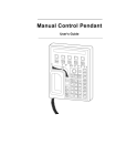
Running Installer
Run the Conifer Rob installer executable.
1) On Windows Vista you will be
prompted to wether you will allow
the unidentified software to modify
your system. To proceed you must
click Allow
2) License Agreement view will open.
You have to select I Agree to go
forward with the installation.
3) You will then have the option of
selecting the default robot model and
language for the Conifer Rob
installation. Select robot model and
language from the list and click Next.
User Manual: Conifer Rob 1.4
6
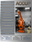
4) Next you are prompted for the
installation directory for Conifer
Rob. It is recommended to keep the
default ”C:\Program Files\Conifer
Rob”. Click Install.
5) Installer will now install some more
files and this takes some time.
6) Finally the installation will complete
and you will be prompted to close the
installer. Click Close.
Now - a shortcut to Conifer Rob has
appeared on your desktop (and also
in Start menu).
Evaluation Period
If a license file or dongle is not installed the Conifer Rob will run in evaluation
version mode for the period of one week after installation. After the evaluation period
the Conifer Rob will require either a license file or dongle to be installed.
Installing License File
If you have an ethernet address (MAC) bound license file (coniferlic.txt) you should
copy it in the directory where you
installed the Conifer Rob. The
default installation directory is
”c:\program files\conifer rob”
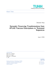
Installing Dongle Driver
If you have been provided with
hardware key (dongle) based license
you will have to install the dongle
drivers. You do this by running the
hardware dongle driver installer from
Alladin. The installer executable in
named 'hdd32.exe'.
1) The driver installer will as
your for the installation language. Select language and click 'OK'
User Manual: Conifer Rob 1.4
7
2) From the Wellcome dialog click
'Next'
3) From the End User License
Agreement dialog you have to
select 'I agree' and click 'Install'
4) Driver will not install. This
may take few minutes
5) Finally, you are greeted with
dialog stating that driver has
been successfully installed.
Click 'Finnish' here to end the
installation.
Configuring FTP access
If the PC that is running Conifer Rob software has TCP/IP network access directly to
the robot that will be running the generated robot programs, you can configure Ftp
access properties to the Conifer Rob and thus allow the software to communicate
directly with the robot via FTP.
The parameters reside in configuration file coniferrob.ini which is located in the
same directory where the Conifer Rob executable is, by default this is ”C:/program
files/Conifer Rob” or ”C:/program files (x86)/Conifer Rob”.
The file has entries
robotftphost=
robotftpusername=
robotftppassword=
robotftpposedirectory=
robotftpprogramdirectory=
User Manual: Conifer Rob 1.4
8
If you fill in to these the robot's host name or IP address, and the username and
password of the robot's ftp service, the directory in the robot where the robot keeps
position (*.pos) files and the program directory in the robot (where robot programs are
stored), the Conifer Rob can access & update these directly in the robot via FTP.
64 bit installations
Conifer Rob is a 32bit Windows application but it runs on 64 bit windows systems
aswell.
User Manual: Conifer Rob 1.4
9
2. User interface
Toolbars
Top Toolbar
New simulation project. Same as 'New' from the File menu.
Open simulation project document. Same as 'Open' from the File menu.
Save simulation project document. Same as 'Save' from the File menu.
Print. Same as Print from the File menu. Prints the current window.
About. Same as About in the Help menu. Displays About dialog that contains
copyright information and the Conifer Rob executable version.
Zoom In.
Zoom Out
Move view to left
Move view to right
Move view to downwards
Move view to upwards
Rotate view
Rotate view
Rotate view
Rotate view
User Manual: Conifer Rob 1.4
10
Rotate view
Rotate view
Reset view to default location
View along Y axis
View along X axis
View along Z axis
Orthographic perspective
Use realistic perspective
Show gemetries in wireframe mode
Show geometries in filled polygon mode
Show geometries in shaded polygon mode
Show / hide selected geometries
Toggle transparency on selected geometries
Righthand Toolbar
Default mouse selection mode
Mouse zoom mode. Left mouse button dragging zooms the view in/out.
Mouse moves viewport. Left mouse button dragging moves the view.
Mouse rotation. Left mouse button dragging rotates the view. Left mouse
button drag with CTRL key pressed down will move the viewport. Mouse
wheel button drag zooms the view in/out.
User Manual: Conifer Rob 1.4
11
Rotating path stage with mouse. After APT source has been loaded in the
system you can run the robot to a stage in a path, select mouse rotation mode
by pressing this button and then rotate the path stage with left mouse button
on the screeen and while holding the button down dragging mouse from left
horizontally.
Point selection/measurement mode. Clicking on geometry will tell the
coordinate location of the point in which user clicked.
Mouse selection mode: Replace selection. In this mode the new selection
replaces the old selection. However, if SHIFT key is pressed during selection
the new selection is added to the current selection instead of replacing it.
Mouse selection mode: Add to selection. In this mode the new selection is
added to the old selection.
Mouse selection mode: Remove from selection. In this mode the new
selection is removed from the old selection. However, if SHIFT key is
pressed during selection the new selection is added to the existing selection.
Stages Toolbar
Move robot to previous stage in current path
Move robot to next stage in current path
Stop animation
Run path as an animation. Visualization will show robot performing the path
stages.
Open stages dialog. The stage dialog shows the current path as a list of stages
and allows detailed observation and manual manipulation of the path stages.
Animation Speed Toolbar
While running robot program as animation
the animation speed can be changed from this
toolbar by either dragging the slider or
entering speed (100% = real time) manually
in the text box.
User Manual: Conifer Rob 1.4
12
Menus
File
New
Create new simulation project. The simulation project will be
initialized using default settings for robot selection, robot home
position, tool container and tool selection.
Open
Open an existing simulation project.
Save
Save currently open simulation project.
Save As..
Save currently open simulation project with different name.
Print
Prints the current window.
Print Preview
Print preview.
Print Setup...
Setup printer and print settings for Print operation
Export STLs
Export currently selected geomeries as STL files
Export APT
Export currently loaded path as APT source
Run Batch
Run a batch job described in a separate text file. This operation
allows you to create batch sets that optimize several *.apt files and
generate robot programs and the main program in a single run.
Upload Program Uploads recently generated robot programs to the robot via FTP
to Robot
Export Original
APT
Exports the *.APT program as it was loaded into Conifer Rob,
with all the changes made in Conifer Rob reverted.
Supervisor
Mode...
Enter supervisor mode.
View
Toolbar
Hide/show top toolbar
Selection Bar
Hide/show left side toolbar
Status Bar
Hide/show status bar at the bottom of the screen
Doublebuffering Enable/disable doublebuffering in 3D visualization.
Zoom
Zoom in/out the view
Move
Pan the view
Rotation
Rotate the view
Projection
Select orthographic/perspective projection for the view
View Mode
Select 3D rendering mode, either wireframe, hidden surface or
User Manual: Conifer Rob 1.4
13
polygon
Clipping
Setup clipping box for the view. Using clipping allows looking
inside geometries.
Hilight Sharp
Edges
Enable/disable edge hilight feature in 3D drawing. Edge hilight
draws sharp edges in the geometry with hilighted color which
makes it easier to quickly see the geometric features in drawing.
Sharp Edges
Treshold...
Setting edge treshold for hilight sharp edges feature.
Hide all / Show
all
Toggles geometry visibility for all geometries in the view
Hide object(s) /
Show object(s)
Toggles geometry visibility for the selected geometries.
Show floor
Toggles floor visibility
Coordinate
System Arrows
Toggles coordinate system arrows visibility
Show Path
Normals
Toggles path normal (i.e. tool orientation) visibility
Capture Picture
Save the currently viewed screen as either a JPG or PNG picture
file.
Save as AVI
File...
Visualize the robot running the current path in an AVI video file.
Surface Color..
Change surface color of currently selected geometries
Background
Color...
Change background color for the view.
Model
Information
Generic information about current simulation project
Load APT File... Load APT path in the current simulation project.
Set Robot
Velocity...
Set robot velocity settings
Path
Positioning...
Position path in workpiece coordinate system
Robot
Positioning...
Positions robot in the robot cell.
Workpiece
Positioning...
Positions the workpiece in the robot cell.
User Manual: Conifer Rob 1.4
14
Check for
Collisions
Checks the currently loaded path for collisions.
Add STL...
Add an obstacle geometry to the robot cell
Remove STL...
Remove an obstacle geometry from the robot cell
Position STL...
Position an obstacle geometry within the robot cell
Position Floor...
Change floor level in Z direction
Manage Tool
Containers...
Manage tool container library
Manage Tools...
Manage tool library
Select Tool
Containers...
Select current tool containers for the robot.
Select Tool...
Select current work tool for the robot.
Help
Help Topics...
Browse help file
About Conifer
Rob...
Version and licensing information about Conifer Rob.
Supervisor State
Some of the operations require supervisor authentication before they become
available. User can enter supervisor state by selecting 'Supervisor Mode..' from the
'File' menu. A supervisor login dialog will appear asking for the current supervisor
password. The same dialog can also be used for changing the supervisor password.
The default supervisor password is 'silirimpsis'.
User Manual: Conifer Rob 1.4
15
Should you ever loose the supervisor password contact the Conifer Rob support for
instructions on how to reset the password.
User Manual: Conifer Rob 1.4
16
3. Visualization
Moving, Zooming and Rotating The View
The view to the robot cell can be panned, zoomed and rotated by several means.
The dropdown menu 'View' contains 'Zoom', 'Move' and 'Rotate' submenus for this
purpse.
Also the toolbar at the top of the main screen contains buttons for navigating the view.
Finally selecting move or rotate modes from the toolbar on the right side of the screen
allows navigating the view with mouse.
Selecting Objects
Geometric objects can be selected by clicking them with mouse. The selected
geometries are drawn with white color. There object selection works differently
depending on which selection mode is selected. There are three different selection
modes can be selected from the left side toolbar.
The default mode replace the current selection with the new one. However, if
SHIF key is pressed down during mouse click the object is added to the selection
instead.
Mouse selection mode: Add to selection. In this mode the new selection is added to
the old selection.
Mouse selection mode: Remove from selection. In this mode the new selection is
removed from the old selection. However, if SHIFT key is pressed during selection
the new selection is added to the existing selection.
Clipping Planes
Clipping planes can be set dropdown menu
View->Clipping...
A dialog will open from which clipping planes
along main axis can be defined. Setting clipping
User Manual: Conifer Rob 1.4
17
planes allows looking inside geometric objects as the surfaces that lie outside the
clipping box are not drawn.
Floor
Setting Floor Level
This option allows changing the floor
level Z coordinate. By default the floor
level is at Z=0.
This operation requires supervisor login.
Hiding Floor
Hiding floor in visualization can be helpful if the floor level is blocking the view to
objects that are positioned below the floor level. Floor visibility can be toggled from
dropdown menu View->Show Foor.
Coordinate Systems
Global Coordinate System
Global coordinate system arrows
are shown on the left side of the
main screen. The global coordinate
system arrows are always on and
unlike other coordinate system
arrows they are not drawn in the
coordinate system origo.
Robot Coordinate System
Robot coordinate system arrows are
enabled from View->Coordinate
System Arrows->Show Robot Coordinate System Arrows. When enabled
coordinate system arrows are drawn in the robot local coordinate system origo.
Workpiece Coordinate System
Workpiece coordinate system arrows are enabled from View->Coordinate System
Arrows->Show Workpiece Coordinate System Arrows. When enabled coordinate
system arrows are drawn in the workpiece local coordinate system origo.
This option is not available when workpiece has not been defined
Path Coordinate System
Path coordinate system arrows are enabled from View->Coordinate System Arrows>Show Path Coordinate System Arrows. When enabled coordinate system arrows
are drawn in the path local coordinate system origo.
This option is not available when APT source has not been loaded.
User Manual: Conifer Rob 1.4
18
Tool Coordinate System
Tool coordinate system arrows are enabled from View->Coordinate System Arrows>Show Tool Coordinate System Arrows. When enabled coordinate system arrows
are drawn in the tool local coordinate system origo.
This option is not available when tool has not been selected.
Path Normals
Showing path normals is enabled
from View->Show Path Normals
menu. When enabled the path
visualization will draw a path
normal for each path stage point
indicating the tool orientation at
that location.
This option is not available when
APT source has not been loaded.
Hiding and Showing Objects
With this option it is possible to hide STL geometries and thus see other geometries
that may be hidden within them. First select the option by clicking on the STL
geometry with mouse and then use this function to hide the geometry. Selection mode
buttons at the right side of the window can be used for selecting multiple STL
geometries when necessary. When some STLs are hidden this menu entry is renamed
as Show object(s) / Show All and selecting this will render the selected objects
visible again.
Tweaking Colors
Surface colors for geometries in the robot cell (the robot parts,
workpiece, tool containers, tool and obstacles) can be modified by
selecting the geometry with mouse (it will be drawn white to show
that it is selected) and then selecting dropdown menu View>Surface Color..
A color picking dialog will appear from which new color can be
selected for the geometry.
Background color for the screen can be modified from dropdown
menu View->Background Color..
Wireframe / Flat / Shaded Visualization
Geometry visualization mode can be changed by selecting
the geometry and then clicking the appropriate
visualization mode icon in top toolbar.
Wireframe mode shows the geometry triangulation
with no filling color.
User Manual: Conifer Rob 1.4
19
Hidden surface mode shows the geometry triangulation with filling color included
Polygon shows the geometies in shaded pologon mode
Toggles the geometry visibility
Toggles the geometry transparency
If no geometries are selected clicking visualization mode icons will change
visualization mode for all geometries in the simulation project.
Capturing Pictures and Animations
Menu operation View->Capture Picture.. will save the current view as a picture file.
JPG and PNG file formats are supported.
Menu operatoin View->Save AVI File.. will save
an animation about the robot running the currently
loaded path. Current screen size and view angle is
used for the video.
First you will be prompted with file dialog for the
name and location of the *.AVI file to be created.
Then, before the video is generated a video codec to be used is prompted.
After video codec is selected the system will take some time in generating the video.
Eventually the video
User Manual: Conifer Rob 1.4
20
4. Managing Robot Cell Layout
Selecting Robot Model
The robot model to be used for new simulation projecs is selected in a configuration
file named 'coniferrob.ini' that resides in the directory where Conifer Rob was
installed.
The file contains entry named 'configuration', for example
configuration=ROBOT_IRB4400
The supported values for the 'configuration' entry are:
Value
Robot Model
ROBOT_IRB2400_15_20
ABB IRB 2400-20/1.5 (Experimental)
ROBOT_IRB4400
ABB IRB 4400-60/1.96
ROBOT_IRB6400_24_120
ABB IRB 6400-120/2.4
ROBOT_IRB6400_25_150
ABB IRB 6400R-150/2.5
ROBOT_IRB6400_28_150
ABB IRB 6400R-150/2.8
ROBOT_IRB6400_30_100
ABB IRB 6400R-100/3.0
ROBOT_IRB6600_175_255
ABB IRB 6600-175/2.55
ROBOT_KR125_PARAT
KUKA 125 PARAT
ROBOT_KR150L110-2
KUKA KR150L110
ROBOT_KR150L110-2_VK
KUKA KR150L110 (customized)
ROBOT_KR150_3
KUKA KR150-3
ROBOT_MOTOMAN_YR_NP50_M_A00
Motoman YR NP50 M-A00 (Experimental)
Changing selected robot for an existing robot simulation project is not supported.
Managing Tool Containers Library
Conifer Rob maintains a library of Tool Containers in each simulation project
separately. Tool containers are geometric objects that are attached between the robot
and the cutting tool. For example an electric engine that rotates the cutting tool is a
tool container. Tooling containers can be nested i.e. electric engine can be attached to
the robot via connector arm or an adapter. The chain of tool containers move the
cutting tool in relation to the robot arm and thus must be taken into account when
calculating the kinematic tool correction for the robot.
Creating New Tool Containers
User Manual: Conifer Rob 1.4
21
New tool containers are added to the library by selecting from dropdown menu View>Manage Tool Containers. ”Manage tool containers” dialog will appear listing
current tool containers in the tool container library of the current project.
Clicking New button will open dialog from which the properties of new tool container
are specified. Following properties must be given:
Name
User given name for the tool container
Connection point X The X coordinate of the point from which the container
to container
connects to the tool container that contains this tool container
(or robot if there is no containing tool container). The
coordinate is specified in the coordinate system of the geometry
of this tool container.
Connection point Y The Y coordinate of the point from which the container
to container
connects to the tool container that contains this tool container
(or robot if there is no containing tool container). The
coordinate is specified in the coordinate system of the geometry
of this tool container.
Connection point Z The Z coordinate of the point from which the container
to container
connects to the tool container that contains this tool container
(or robot if there is no containing tool container). The
coordinate is specified in the coordinate system of the geometry
of this tool container.
Yaw rotation of the The YAW rotation in the connection point to the containing
connection point to tool container (or robot if there is no containing tool container).
container
This effectively rotates the geometry of this tool container AND
the contained tool containers and the tool.
Pitch rotation of the The PITCH rotation in the connection point to the containing
connection point to tool container (or robot if there is no containing tool container).
container
This effectively rotates the geometry of this tool container AND
User Manual: Conifer Rob 1.4
22
the contained tool containers and the tool.
Roll rotation of the The ROLL rotation in the connection point to the containing
connection point to tool container (or robot if there is no containing tool container).
container
This effectively rotates the geometry of this tool container AND
the contained tool containers and the tool.
Connection point X The X coordinate of the point to which the contained tool or
contained
tool container will be attached to. The coordinate is specified in
tool/container
the coordinate system of the geometry of this tool container.
Connection point Y The Y coordinate of the point to which the contained tool or
to the contained
tool container will be attached to. The coordinate is specified in
tool/container
the coordinate system of the geometry of this tool container.
Connection point Z The Z coordinate of the point to which the contained tool or
to the contained
tool container will be attached to. The coordinate is specified in
tool/container
the coordinate system of the geometry of this tool container.
Yaw rotation of the The YAW rotation of the contained items. This setting rotates
connection point to the contained items around the connection point to contained
the contained
items.
tool/container
Pitch rotation of the The PITCH rotation of the contained items. This setting rotates
connection point to the contained items around the connection point to contained
the contained
items.
tool/container
Roll rotation of the The ROLL rotation of the contained items. This setting rotates
connection point to the contained items around the connection point to contained
the contained
items.
tool/container
Geometry
An STL geometry file defining the geometry for this coordinate
system. Pressing the LOAD button will open a file dialog from
which the file to be used can be selected.
Tool container
weight
Weight of the tool container in kilograms [Kg]
Deleting Tool Containers
To delete a tool container from projects tool container library open ”Manage tool
containers” dialog by selecting from dropdown menu View->Manage Tool
Containers. Select a tool container you wish to delete from the list and click Delete
button.
Modifying Tool Containers
To modify a tool container in projects tool container library open ”Manage tool
containers” dialog by selecting from dropdown menu View->Manage Tool
User Manual: Conifer Rob 1.4
23
Containers. Select a tool container you wish to delete from the list and click Edit
button. A dialog similar to used when creating new tool containers will open from
which the tool container properties can be modified.
Setting Default Tool Containers
System maintains a set of default tool containers which are initialized to the tool
container library for new simulation projects. You can revert the simulation project to
this default library by clicking Load defaults button in the ”Manage tool containers”
dialog.
Also, you can replace the default tool container library with the current one by
clicking the Save defaults button.
The default tool container library is stored in the ”ToolContainers” directory in the
Conifer Rob installation directory (typically c:\program files\conifer rob). If you want
to take a backup of the tool container library just backup this directory. To revert back
to the backup replace the contents of the ”ToolContainers” directory from your
backup.
Managing Tools Library
Creating New Tools
Conifer Rob maintains a library of tools separately in each simulation project.
New tools are added to the library by selecting from dropdown menu View->Manage
Tools. ”Manage tools” dialog will appear listing current tools in the tool library of the
current project.
Clicking New button will open dialog from which the properties of the new tool are
specified. A tool can either be a simple one or a complex one. Simple tools are circle
profiled tubes with optional rounding in the tool tip. Conifer Rob generates the
geometry for simple tools automatically from the given parameters. For complex tools
the tool geometry must be given as an STL file.
Following properties must be given to all tools:
Name
User given name for the tool
Hotspot offset
Hotspot offset from the tip of the tool geometry in the direction
of the tool axis. Positive value moves the hotspot away from
the tool. Negative value moves the hotspot inside the tool.
Hotspot is the point which the robot considers as the tool
location when running the robot program i.e. the hotspot is the
point that will follow the defined path.
Weight
Tool weight in kilograms [Kg]
Following information must be given for simple tools:
Length
Tool length in millimeters (mm)
Corner radius
Tool tip rouding corner radius in millimeters (mm)
User Manual: Conifer Rob 1.4
24
Diameter
Tool profile diameter in millimeters (mm)
Following information must be given to complex tools:
Profile geometry
An STL geometry file defining the geometry for this coordinate
system. Pressing the LOAD button will open a file dialog from
which the file to be used can be selected.
Connection point X For complex tools: The X coordinate of the point from which
to container
the complex tool geometry connects to the tool container. The
coordinate is specified in the coordinate system of the given
geometry file.
Connection point Y For complex tools: The Y coordinate of the point from which
to container
the complex tool geometry connects to the tool container. The
coordinate is specified in the coordinate system of the given
geometry file.
Connection point Z For complex tools: The Z coordinate of the point from which
to container
the complex tool geometry connects to the tool container. The
coordinate is specified in the coordinate system of the given
geometry file.
Yaw rotation of the The X coordinate of the point to which the contained tool or
conneciton point to tool container is attached to. The coordinate is specified in the
container
coordinate system to the geometry of this tool container.
Pitch rotation of the The X coordinate of the point to which the contained tool or
conneciton point to tool container is attached to. The coordinate is specified in the
container
coordinate system to the geometry of this tool container.
Roll rotation of the The X coordinate of the point to which the contained tool or
conneciton point to tool container is attached to. The coordinate is specified in the
container
coordinate system to the geometry of this tool container.
User Manual: Conifer Rob 1.4
25
Deleting Tools
To delete a tool container from projects tool library open ”Manage tools” dialog by
selecting from dropdown menu View->Manage Tools. Select a tool you wish to
delete from the list and click Delete button.
Modifying Tools
To modify a tool in projects tool library open ”Manage tools” dialog by selecting from
dropdown menu View->Manage Tools. Select a tool you wish to delete from the list
and click Edit button. A dialog similar to used when creating new tools will open
from which the tool properties can be modified.
Setting Default Tools
System maintains a set of default tools which are initialized to the tools library for
new simulation projects. You can revert the simulation project to this default library
by clicking Load defaults button in the ”Manage tools” dialog.
Also, you can replace the default tool library with the current one by clicking the Save
defaults button.
The default tool library is stored in the ”Tools” directory in the Conifer Rob
installation directory (typically c:\program files\conifer rob). If you want to take a
backup of the tool library just backup this directory. To revert back to the backup
replace the contents of the ”Tools” directory from your backup.
Workpiece Positioning
This operation is available only after supervisor login. Also, before you can position
the workpiece you have to define the workpiece geometry.
To move the workpiece in the system select from dropdown menu Model>Workpiece Positioning.. or alternatively from the left toolbar Select Workpiece
Position.
User Manual: Conifer Rob 1.4
26
An 'Edit Workpiece Position' dialog will open.
From this dialog you can set the workpiece
location in the robot cell for this simulation
project document. Location is given in global
coordinate system. By clicking Load Default
you can load the system default location for the
workpiece position and by clicking Save
Default you can store the workpiece location in
the current simulation document as the system
default. The system default is used for all new
simulation project documents as default
workpiece location.
Workpiece location can also be imported from
a file. The supported file format is a simple text
file consisting of 6 or 7 decimal numbers separated by either space or tab character(s).
If the file contains 6 numbers the position is assumed to be in YPR format
(x,y,z,yaw,pitch,row) and if the file contains 7 numbers the format is assumed to be in
quaternion format (x,y,z,q1,q2,q3,q4). The position export function always export the
position in quaternion format.
Finally, the workpiece position can be uploaded to a robot with Export to robot and
loaded from robot with Import from robot. In exporting the name of the *.pos file is
asked and the position is then uploaded via FTP to the robot. In importing the Conifer
Cast lists all the *.pos files in the position file directory in the robot and lists them. To
download the position select the position file and click Ok. The FTP properties need
to be configured for this, see Installation chapter for details.
Robot Position
Changing Robot Position
This operation is available only after
supervisor login.
To change the robot location and orientation
the robot cell for this robot simulation project
select from dropdown menu Model->Robot
Positioning..
User Manual: Conifer Rob 1.4
27
A 'Robot positioning' dialog will open from which you can change the robot location
and orientation in the robot cell.
Default Robot Position
To modify the default robot location used for new robot simulation projects you have
to create/modify a file named 'robot.pos' in the Conifer Rob installation directory.
This file as the following syntax:
X Y Z rotZ
..where the X, Y and Z define the default robot location in the robot cell and the rotZ
defines the robot rotation around the Z axis in degrees.
Example:
100.0 0 0 45
Setting Robot Home Position
The robot home position for current simulation project is set in Optimization
Settings. See chaper Optimization Settings for details on this.
The default position for robot home position is defined in file home.jnt which locates
in the installation directory of the Conifer Rob. The format of the file is following:
<jount1> <joint2> <joint3> <joint4> <joint5> <joint6>
..where jointN gives the joint N rotation value for home position in degrees.
Example:
-0.000 -0.000 -0.000 0.000000 0.000000 0.000000
Managing Obstacles
Creating New Obstacles
This operation is available only after
supervisor login.
You can import STL geometries as
obstacles to your robot simulation
project. These obstacles are visualized
on the screen and used in the collision
detection to determine wether the robot program is safe to run.
User Manual: Conifer Rob 1.4
28
To import a new obstacle to the system select from dropdown menu Model->Add
STL... and an 'Add new geometry to model' dialog will open. Clicking Browse will
open a file dialog from which you can select an STL file defining the obstacle
geometry to be imported in the simulation project. To Object name edit line give a
human readable name for the obstacle. This name will be used for referring to the
obstacle in the user interface.
After clicking OK from the 'Add new
geometry to model' dialog an 'Object
positioning dialog' will open. On the left
side you see a list of obstacle geometries in
the simulation project. The newly imported
obstacle is automatically selected as
default. On the right side there are entries
for positioning and rotating the geometry
in the robot cell. Making changes to these
entries becomes visible on the screen
immediately. After the obstacle geometry
has been positioned to it's correct location
in the robot cell click OK.
Deleting Obstacles
This operation is available only after supervisor login.
To remove an obstacle from the robot model select from
dropdown menu Model->Remove STL..
A 'Remove object' dialog will open. The dialog shows the
list of obstacles in the current simulation project. Select the
obstacle you wish to remove and click Remove to remove
the obstacle.
Moving Obstacles
This operation is available only after supervisor login.
To move obstacles in the robot cell select from dropdown menu Model->Position
STL... An 'Object positioning dialog' will open from which the obstacles can be
moved and rotated within the robot cell.
Setting Default Obstacles
The Conifer Rob will load all the STL files in the subdirectory named 'Obstacles'
under installation directory as initial default obstacles for any new robot simulation
document. You can modify the default obstacles by creating/deleting STL files
from/to this directory. Obstacles from current robot simulation project can be exported
to be used as default by selecting the obstacle geometry with mouse and using the
Export STLs function found in the File menu. The exported STL file should then be
copied under the 'Obstacles' subdirectory under Conifer Rob installation directory.
User Manual: Conifer Rob 1.4
29
5. Path Setup
Selecting Workpiece Geometry
To set up the workpiece geometry for the simulation project either select Select
Workpiece STL.. from the left hand toolbar. A 'Select Workpiece Model' dialog will
open. From this dialog you can define box shaped standard workpiece geometry or
load a complex workpiece geometry as an STL file. Complex workpiece can be of
arbitary shape.
For standard workpiece
geometries select either one
of the given sizes (3000mm
x 2200mm, 2500mm x
2000mm or 2000mm x
1600mm, 1400mm x
1200mm) or select the
Custom choice and give the
dimensions manually. Also
give the workpiece geometry thickness in the Mold Height entry. For complex
workpiece geometry clicking Other button will open a file dialog by which you can
select an STL geometry file to be used as a workpiece geometry.
Frame is a solid geometry around the work piece that holds the workpiece together in
correct place. Conifer Rob can generate a frame object around the work piece
automatically using offsets. The offsets define the thickness of the frame in x and y
directions around the frame (x & y axis in workpiece coordinate system). The min and
max z edges of the frame are open i.e. There is no frame wall in those directions as the
work on the workpiece is done from the max z direction when frames are used (again,
workpiece coordinate system). In addition to automatically generated frames the fram
e can also be modeled in CAD system and imported in Conifer Rob in STL format
using Select button.
Often, especially when frames are used, it is not feasible to measure workpiece
position from the workpiece coordinate system origo which resides in the corner of
the workpiece box. In such case, if realistic positioning of the workpiece and frame
geometry are desired, a measurement point offsets can be given to move the
workpiece coordinate system away from the workpiece box corner to a location where
measurement is more practical.
Selecting Tool Containers
Tool containers are objects that are attached to the robot and to which the tool then be
attached. Tool containers are managed in tool container library.
To select the tool containers to be used in simulation select from dropdown menu
Model -> Select Tool Containers. A 'Tool Containers' dialog will open up. This
dialog shows the list of the tool containers currently attached to the robot.
User Manual: Conifer Rob 1.4
30
Attaching Tool Container To Robot
To attach a tool container to robot open 'Tool Containers' dialog by selecting
dropdown menu Model -> Select Tool Containers. In this dialog click Add button.
A 'Select Tool Container' dialog will appear. Select the tool container to add and click
Select. Confirm the change by clicking OK in the 'Tool Containers' dialog.
Removing Tool Container From Robot
To remove a tool container from robot open 'Tool Containers' dialog by selecting
dropdown menu Model -> Select Tool Containers. Select the tool container to
remove from the robot and click Remove. Confirm the change by clicking OK in the
'Tool Containers' dialog.
Selecting Default Tool Containers
When new simulation project is created the default tool containers will be attached to
the robot. To modify this default tool container selection modify the tool container
selection in the current simulation project and then from the 'Tool Containers' dialog
click Save Default. This will save the current tool container selection as default which
will be used for all new simulation projects.
To revert back to default tool container selection click Load Default button in the
'Tool Containers' dialog.
Selecting Tool
Attaching Tool
User Manual: Conifer Rob 1.4
31
To select the current tool attached to the tool container (or in the absense of tool
container - the robot itself) select dropdown menu Model -> Select Tool. A 'Select
Tool' dialog will open. This dialog lists all the tools in the simulation projects tool
library. Select the new tool to be used from the list and click Select.
Selecting Default Tool
When new simulation project is created the default tool will be attached to the tool
container. To modify this default tool selection modify the tool selection in the
current simulation project and then from the 'Select Tool' dialog click Save Default.
This will save the current tool selection as default which will be used for all new
simulation projects.
To revert back to default tool selection click Load Default button in the 'Select Tool'
dialog.
Reading APT File
This operation requires that the workpiece geometry has been defined first.
In order to load an APT path to Conifer Rob select dropdown menu Model -> Load
APT File or alternatively click Read APT-file button from the left hand toolbar.
A file dialog will open for selecting the APT file to be loaded. Select the APT file and
click Ok. The APT file will not be loaded to the simulation project.
Conifer Rob will perform initial reachability analysis for the path defined in the APT
file and renders the path to the screen so that reacable fragments of the path are
rendered with white color while non-reacable framgments are rendered with red color.
If some (or all) parts of the path are unreacable you can try to fix this by moving the
path within workpiece using Path Positioning.. function in the Model menu. If you
have supervisor access you can also try to move the workpiece or the robot in the
robot cell to make the path reachable.
User Manual: Conifer Rob 1.4
32
Now that the path has been loaded it is possible to animate the robot running the path.
Also it is possible to do modifications to the path via Show Path Stages operation
found in the left hand toolbar.
Path Positioning
This operation is available only after APT
file has been read in.
You can move the path positionining in the
workpiece geometry by selecting Model ->
Path Positioning... A 'Path positioning'
dialog will open from which the path
position and Z rotation in the workpiece
coordinate system can be changed. Give new
path location and orientation and click OK. Conifer Rob will not recalculate the
reacability for the path according to new path position.
Robot Animation
Once the APT file has been read the Conifer Rob can animate the robot running the
given path. Use Stages Toolbar in the top of the screen to run the animation. You can
also use the Show Path Stages function found in the left hand toolbar to navigate the
path in detail.
User Manual: Conifer Rob 1.4
33
6. Path Optimization
In path optimization Conifer Rob will determine the approach (and exit) from the
robot home position. Most importantly the optimization process will look for the best
possible robot configuration for running the path in current robot cell setup and
optimize the tool rotation around the tool symmetry axis. The loaded APT source
defines only 5 degrees of freedom leaving the rotation around the tool axis open. The
optimization will bind this extra degree of freedom and selects a rotation for each step
so that robot joint movements are minimized and robot singularity points are avoided.
Also – when collision avoidance feature is enabled – the optimization process will do
collision analysis for the robot running the path and selects the tool axis rotation so
that collision is avoided.
Path Optimization Settings
The set properties for optimization process select Path Optimization Settings from
the left hand toolbar.
The values you can set here are:
Name
Description
Path Z offset
Moves the path in Z direction
Maximum Path Length Maximum path length in steps. Paths longer than this will
be split in several path segments.
Max Approach Length
Maximum allowed apprach movement length.
Weight
Optimization criteria – tells how much the optimization
emphasis the optimization gives for minimizing the robot
joint angle changes and how much the optimization tries to
keep the robot joint angles as close as possible to the home
position.
Translation Resolution
Translation resolution used in approximating joint
movements as a sequence of linear movements. Also used
User Manual: Conifer Rob 1.4
34
in linear motion check. Smaller value gives better
optimization results but takes longer to optimize.
Rotation Resolution
Rotation resolution for linear motion check. Smaller value
gives better optimization results but takes longer to
optimize.
Rotation Limit
Min/Max values for the tool rotation. By default these are
-180deg to +180deg meaning full circle is available for tool
rotation. By changing these values it is possible to deny
certain tool rotation sectors to be used in path optimization.
Singularity Limit
Limit angle in degrees. Defines how close to a singularity
point robot is allowed to move.
Joint Margin
Safety limit for robot joint angle limits in degrees. Any
joint in robot is not allowed to get any closer to its angle
limit than this value.
Joint 5 Safety Margin
Safety limit for robot's 5th joint angle limit in degrees. The
5th joint in the robot is not allowed to get any closer to its
angle liit than this value.
Configuration
constraints
By deselecting some configurations here it is possible to
force the optimization not to use certain robot
configurations.
Collision
detectionwhile
optimizing path
When enabled the optimization process will do collision
check for each path stage and selects only configurations
and tool rotations in which collisions do not occur.
Robot home position
This entry defines the robot home position to be used.
Home position is defined as joint angles in degrees.
Also, robot joint angle limits can be configured here
Reduce speed at corners If selected the optimization will monitor for robot tool
acceleration speed at corners and if it exceeds the given
trenshold acceleration it will run change the robot program
so that the corner is run slowly enough so that the
acceleration treshold is not exceeded.
Visit home between
segments
If selected the animation will add visit to the robot home
position between every robot program segment.
Load default home
This button will replace the currently set robot home
position with the default.
Save default home
This button will store the currently set robot home position
as the default.
User Manual: Conifer Rob 1.4
35
Robot Velocity Settings
To set the robot velocity settings click Robot
Velocity Settings button in the left hand side
toolbar.
Following velocity settings can be set:
Name
Description
Maximum Feed Rate
Maximum feed rate. This is used as default if feed rate
is not given in APT file.
Rapid Movement Speed
Movement speed for rapid movement commands.
Joint Movement Ratio
Relative joint velocity factor for joint movements.
Default Tool RPM
Default tool rotation speed. This is used if rotation
speed is not specified in APT file.
Movement Precision
Tooling tolerance
Path Optimization
This function requries that the APT file has been loaded in.
Path optimization is started from the left hand side toolbar button Optimize Path.
A 'Progess Ouput' dialog will open to which the optimization process will write it's
progress information.
The path optimization will try out the loaded path in all possible 8 robot
configurations and tries determine the optimal tool rotation so that all stages are
reacheable and robot joint rotation velocities are minimized and robot operates as
close as possible to the home
position joint angles.
Optimization process inserts the
path an approach segment from the
robot home position and exit
segment from the path end point
back to the robot home position. If
path is very long the optimization
process will split the path into
several segments so that each segment can be loaded separately to the robots limited
memory so that larger paths can be run in separate fragments with robots having
limited controller memory.
User Manual: Conifer Rob 1.4
36
Manual Path Manipulation
Viewing Path Stages
This function requires that APT has been loaded to the project.
Selecting View Path Stages from the left hand side toolbar will open stages dialog
which shows the currently active path as a list of command steps. The currently active
step is shown in the dialog as selected and during animation this selection will move
forward as the program is run forward. Also, clicking a stage in the stages list will
bring the robot to that location
in the program.
The list can shows the path
stages in two modes. First mode
(Show Tool Position in
Workpiece CS) shows the tool
location and orientation in path
coordinate system.
The second mode (Show Tool
Position in Robot CS) shows the tool location and orientation in the robot coordinate
system.
The third mode (Show Joint Angles (Abb Style)) shows the location as robot joint
angles in ABB style. In this form the 3rd joint angle is given relative to vertical plane
instead of 2nd joint.
The fouth mode (Show Joint Angles (deg)) shows the location as robot joint angles.
For each step the program feed rate (Speed) and Tool rotation speed (RPM) is shown.
Column APT tells wether the stage is part of the work path or a movement command
added by the Conifer Rob path optimization process.
Creating New Path Stages
User Manual: Conifer Rob 1.4
37
In 'Robot path stages' dialog it is
possible to modify stages in the
path.
To add a new point in path select
the position to which you want to
add the new stage in the path and
click Add in the robot path stages
dialog. An 'Edit Path Stage' dialog
will open with the fields pre-filled
with the values of the stage you
selected. This dialog allows
modifying the tool position in
either path coordinate system or
robot coordinate system. For tool
orientation both YPR and quaternion system are supported. Modify the values here
and click OK to add a new stage before the stage you selected. To test the location
first click Apply. This will store the new path stage to the path and move the robot to
this new location so that you can preview on the screen the change was correct and
keep the dialog open for the new stage so that you can make corrections.
The properties for new stage are:
Name
Description
Position X
Tool location for the stage in selected coordinate system
Position Y
Tool location for the stage in selected coordinate system
Position Z
Tool location for the stage in selected coordinate system
Orientation Yaw
Tool orientation for the stage (deg)
Orientation Pitch
Tool orientation for the stage (deg)
Orientation Roll
Tool orientation for the stage (deg)
Orientation Q1
Tool orientation for the stage (quaternions)
Orientation Q2
Tool orientation for the stage (quaternions)
Orientation Q3
Tool orientation for the stage (quaternions)
Orientation Q4
Tool orientation for the stage (quaternions)
Movement Speed Rapid
Movement to the stage location is to be done as rapid
movement
Movement Speed Normal
Movement to the stage location is to be done with given
speed
Movement Type
Linear movement means tool will move to the new stage
location along straight linear path from the previous
stage. Joint movement will rotate all joints at nearlylinear rotation speed to reach the new location. In the
joint movement type the path of the tool can become
User Manual: Conifer Rob 1.4
38
quite complex and this mode is usually used only in
approaching the work path from the robot home position
and in the exit stage from the path to the home position.
Tool RPM
Tool rotation speed for the stage
Deleting Path Stages
To remove a path stage select the stage (or several stages – this can be done either by
dragging the mouse on the list or keepign the SHIFT key down while clicking on the
list) from the list and click Remove button.
Modifying Path Stages
Moving Stage
To move a stage location click the stage you want to modify on the list and then click
Edit. 'Edit Path Stage' dialog will open. Change the path location from the dialog and
click OK.
Rotating Stage
To manually change the tool rotation for a path stage select the path stage (or several
stages) from the stages list and click the +/- (plus/minus) buttons on the dialog. The
path stages YAW rotation (rotation around the tool axis) will change and the robot on
the screen will be adjusted to the new rotation. Note that
Changing Stage Properties
As when creating a new path stage to the path the 'Edit Path Stage' can also be used
for modifying other path stage properties such as the movement speed, movement type
and tool rotation RPM .
User Manual: Conifer Rob 1.4
39
7. Collision Detection and Avoidance
Collision Detection
This option is only available after APT file has been read in.
To do collision detection for the current path select from dropdown menu Model ->
Check for Collisions..
The Conifer Rob will now simulate running the robot program in memory and checks
each path step for collision. If collisions are found the colliding parts in the part are
rendered with red color and the robot is driven to the location where the first collision
occurred.
The collisions are checked between all the robot and tool container parts and the work
piece and obstacles. The collisions of the tool geometry are checked against the
obstacles but not the workpiece.
IMPORTANT: Currently, the collision detection does NOT check the approach (from
the home position) and the exit (to the home position).
Collision Avoidance
During path optimization if the
Collision Detection while
Optimizing option is selected from
the Path Optimization Settings
the system will do collision
avoidance during path optimization.
The optimizatio process checks
each path step for collision and
accepts only the configurations and
tool rotations in which it does not
find collisions.
User Manual: Conifer Rob 1.4
40
8. Exporting Results
Exporting APT
This function requires that an APT file has been loaded to the simulation project.
To export the path as APT file select from dropdown menu File->Export APT..
A file dialog will open asking the file name for the new APT file to be exported.
The exported file will contain the path and possible modifications made to it in the
Conifer Rob. The exported APT is presented in the workpiece coordinate system i.e.
path position translation is applied to the path points before export. Thus it is possible
to import and APT path to Conifer Rob, move and rotate it, modify individual path
points in it and then export the modified path back to APT file for further use.
However, because APT format defines only 5 degrees of freedom the exported APT
does not contain the tool rotation optimization created by Conifer Rob.
Generating Robot Program
This option is available only after path optimization has been done.
To export the optimized path as a robot program select 'Write Control Files' from the
left hand toolbar. A file dialog will appear asking for a file name for the robot
program to be generaetd. Give a file name for the robot program and click Ok.
Now the Conifer Rob will generate a robot program which can be loaded in to a real
robot for running.
Uploading Robot Program to Robot
If the workstation on which the Conifer Rob is running has a working TCP/IP
connection to the robot, if FTP properties have been defined in Conifer Rob
installation and if the robot supports FTP access, you can after generating the robot
program upload it automatically to the robot. To do this, select Upload program to
robot from the File menu.
Conifer Rob will open an FTP connection to the robot and upload the last generated
robot programs to robot in directory specified by robotftpprogramdirectory entry in
coniferrob.ini (see Installation chapter for details).
User Manual: Conifer Rob 1.4
41
9. Batch Runs
Using batch files allows optimizing and generating robot programs from several APT
paths in one run. The task is defined in a batch file that should have a postfix .crbbat
in its file name. The .crbbat file consists of lines, each defining one *.apt file to
process.
The line structure of the .crbbat file is
handleapt <mname> <aptfilename> <wpfilename> <pposfilename>
..where <mname> is the module name, <aptfilename> is the file name of the *.apt file
defining the path to be processed, <wpfilename> is the file name of the *.pos file
defining workpiece position and <pposfilename> is the file name of the *.pos file
defining the path positioning of the path wihin workpiece.
The batch function is started from selecting Run batch from File menu. A file dialog
will open asking for you to provide the .crfbbat file that defines the batch to run.
When you do this you should have a simulation document open that defines the Robot
cell and optimization parameters for the batch. Once batch file is selected the current
document is saved automatically and for each handleapt command the system will
create a new simulation document (*.crb), load the apt file given in the .crbbat file line
to the simulation d9ocument, set workpiece position and path position as defined in
the .crfbbat line, run optimization with the current optimization settings and generates
robot program to the directory where .crfbbat file resides.
If main program template is defined as Templates\mainprogram.template in the
directory where Conifer Rob executable resides (typically this is ”c:\program
files\conifer rob” or c:\program files (x86)\conifer rob”) the batch operation will also
generate a main file according to the definitions in the template file.
If the batch operation runs successfully the File->Upload program to robot
operation can be used to upload the generated modules and main program directly to
the robot via FTP.
User Manual: Conifer Rob 1.4
42
APPENDIX A: Robot Program Templates
How robot program generation works?
Conifer Rob uses templates for generating robot program from the optimized work
path in the memory. The data in the template file is copied to the robot program as is.
However – specially formated items in the template file – so called 'tags' are given
special treatment. The tags are used for iterating data in optimized path and expanding
data from the path to the robot program. The data in the oprimized path can be
accessed via variables. The template expansion procedure can also modify the values
of variables and thus maintain an internal state during the template expansion.
Templates
The used templates are defined in the coniferrob.ini configuration file that resides in
the Conifer Rob installation directory (which is typically the c:\program files\conifer
rob). The template information is stored in the configuration file entry 'template'. The
value of the entry has a following structure:
template=<postfix1>;<templatefile1>[;<postfix2>;<templatefile2>[..]]
...where the <postfixN> is the default file name postfix for the file generated with
template and the <templatefileN> is the template file used for generating the file. If
several template files are given the they are each run separately with the same path
data and will generate a separate result file. This can be used to generate robot
program that consist of several files - such as the KUKA robot programs with the
program consisting of both *.dat and *.src files.
Example:
template=.dat;Templates/template-kuka-vkrc-2dat.txt;Templates/template-kuka-vkrc-2-src.txt
..will configure the system to run two template files – first generating a *.dat file and
the second generating an *.src file.
The template files are stored in the Conifer Rob installation directory subdirectory
'Templates'.
Variables
Variables are organized in scopes which can contain other scopes. The main level
scope is called GLOBAL scope. The variables provide access to data that is expanded
User Manual: Conifer Rob 1.4
43
to robot program as specified by robot program template. In addition to predefined
variables a template can also define an manipulate variables of its own.
GLOBAL scope
Variables for main program
Name
Description
NAME
Main program filename base (generated from the
simulation project file (*.crb) name
Sub-scopesfor main program
Name
Description
MODULE
Modules generated in this run
Variables for robot program modules
Name
Description
LFTOOLX
Tool correction in X
LFTOOLY
Tool correction in Y
LFTOOLZ
Tool correction in Z
LFTOOLQ1
Tool correction rotation in quaternions
LFTOOLQ2
Tool correction rotation in quaternions
LFTOOLQ3
Tool correction rotation in quaternions
LFTOOLQ4
Tool correction rotation in quaternions
LFTOOLR1
Tool correction rotation in YPR angles (degrees)
LFTOOLR2
Tool correction rotation in YPR angles (degrees)
LFTOOLR3
Tool correction rotation in YPR angles (degrees)
LFW1
Workpiece location X relative to robot coordinate system
LFW2
Workpiece location Y relative to robot coordinate system
LFW3
Workpiece location Z relative to robot coordinate system
LFWR1
Workpiece rotation in quaternions
LFWR2
Workpiece rotation in quaternions
LFWR3
Workpiece rotation in quaternions
LFWR4
Workpiece rotation in quaternions
LFWRYPR1
Workpiece rotation in YPR angles (degrees)
User Manual: Conifer Rob 1.4
44
LFWRYPR2
Workpiece rotation in YPR angles (degrees)
LFWRYPR3
Workpiece rotation in YPR angles (degrees)
FEEDRATE
Maximum feed rate given in robot velocity settings
RAPIDSPEED
Speed for rapid movement operations, given in robot
velocity settings
TOLERANCE
Tooling tolerance
AXISVELOCITY
Maximum allowed axis velocity for the robot
OUTBASE
File name of the generated robot program file with the
running number ohmitted
TOOLNAME
Name of the currently selected tool
SPINDLERPM
Default spindle rotaton speed, given in robot velocity
settings
FILEEXTENSION
Filename postfix for the generated file. Robot program
template can modify this.
WORKPIECENAME
Name of the workpiece.
ROTATIONVEL
Obsolete, included for backward compatibility
ILINES
Count of commands in paths
IJOINTS
Count of joints in the robot
TOOLNR
Selected tool index in the tool library
MODULENAME
Suggested name for the program module. This is generated
from workpiece positioning name and the APT file name.
WORKPIECEPOSITIONNA
ME
Name of the workpiece positioning. This is given in
workpiece setup dialog.
TOOLWEIGHT
Combined weight of the tool and tool contaienrs in
kilograms (given in the tool library)
Sub-scopes for robot program modules
Name
Description
JOINTS
Contains the robot home position as joint angles.
PATH
Paths in this robot program. If the APT program is large
the optimization may split the program into several paths
depending on path size limits given in optimization
parameters.
MODULE scope
User Manual: Conifer Rob 1.4
45
Variables
Name
Description
NAME
Name of the program module
HASTOOLNAME
0=tool name was not defined, 1=module has tool name
defined
TOOLNAME
Tool name to use in program module
Sub-scopes
None
JOINTS scope
Variables
Name
Description
LF_JOINT1
Joint angle of the robot home position for the 1st joint
LF_JOINT2
Joint angle of the robot home position for the 2nd joint
LF_JOINT3
Joint angle of the robot home position for the 3rd joint
LF_JOINT4
Joint angle of the robot home position for the 4th joint
LF_JOINT5
Joint angle of the robot home position for the 5th joint
LF_JOINT6
Joint angle of the robot home position for the 6th joint
Sub-scopes
None
PATH scope
Variables
None
Sub-scopes
Name
Description
COMMAND
Robot commands forming the containing path
COMMAND scope
Variables
None
User Manual: Conifer Rob 1.4
46
Sub-scopes
Name
Description
MOVEL
Linear movement command(s)
MOVEL scope
Variables
Name
Description
LFP1
Tool target x coordinate in workpiece coordinate system
LFP2
Tool target y coordinate in workpiece coordinate system
LFP3
Tool target z coordinate in workpiece coordinate system
LFQ1
Tool target orientation in quaternions
LFQ2
Tool target orientation in quaternions
LFQ3
Tool target orientation in quaternions
LFQ4
Tool target orientation in quaternions
LFR1
Tool target orientation in YPR angles (deg)
LFR2
Tool target orientation in YPR angles (deg)
LFR3
Tool target orientation in YPR angles (deg)
IC1
Angle sector flag 1
IC2
Angle sector flag 2
IC3
Angle sector flag 3
ISRAPID
1 is command is rapid movement, otherwise 0
FEEDRATE
Feed rate for movement
SPINDLERPMCHANGED
1 if spinlde RPM has changed since last movement
command
SPINDLERPM
Spindle RPM for this movement
Sub-scopes
None
User Manual: Conifer Rob 1.4
47
Template Language Specification
Static text
All text not enclosed in ${ .. } is considered as static text and will be expanded to the
robot program as it is.
However, if the static text to be expanded contains ${ it must be presented as ${}
Example:
Oli hyva marjavuosi ja siksi saatiiin paljon mustikoita $
{}} foo $$ $$$ ..testidataksi
..will expand to...
Oli hyva marjavuosi ja siksi saatiiin paljon mustikoita $
{} foo $$ $$$ ..testidataksi
Variable expansion
Variables in global scope are expanded with following syntax:
${variablename}
..where the variablename is the variable name.
Variables in an iterated subscope (see FOREACH statement) are expanded with
following syntax:
${scopealias.variablename}
..where the scopealias is the scopealias given in containing FOREACH statement and
the variablename is the name of the variable in the interated scope instance.
${FOREACH <subscopename> <scopealias>} ... ${ENDFOREACH
<scopealias>}
Foreach statement iterates over all found subscope instances of current scope having given scope name
<subscopename>. Within the FOREACH, ENDFOREACH pair the variable values in the subscope can
be referred with scope prefix <scopealias>.
The iteration count will be stored in scope variable INDEX as numeric value starting from 0.
Example:
User Manual: Conifer Rob 1.4
48
${FOREACH PATH P}
${FOREACH COMMAND C}
${FOREACH MOVEL M}
${P.INDEX}
${M.LFP1}
${ENDFOREACH M}
${ENDFOREACH C}
${ENDFOREACH P}
..will iterate through all PATH subscopes at global scope and for each scope found there it will iterate
over all contained COMMAND subscopes and for each such scope found it will iterate over all
MOVEL subscopes found. For all found MOVEL subscopes a running number of the containing
PATH and the value LFP1 variable in the MOVEL scope will be expanded.
${SET <variablename> = <expression }
Set statements stores the value of given expression <expression> in a global variable
<variable>.
Example:
${SET lastSpindleValue = 0}
..will set the variable 'lastSpindleValue' in the global scope to numerical value zero.
The set value can then be expanded as...
${lastSpindleValue}
...or referred in expression as...
${IF lastSpindleValue=0}
...
${ENDIF}
${IF <variablename> <eqop> <expression> } ${ENDIF}
IF, ENDIF pair will expand the data between the IF and ENDIF if the expression
<expression> expands to a value that matches with value of 'variablename' as
specified by comparison operation <eqop>.
<eqop> can either be '=' meaning equal value or '!=' meaning non-equal value.
User Manual: Conifer Rob 1.4
49
Example:
${IF lastSpindleValue=0}
StartSpindle;
${ENDIF}
${IF lastSpindleValue!=0}
StopSpindle;
${ENDIF}
.. will expand text 'StartSpindle;' to the robot program if global variable
'lastSpindleValue' has zero value. Otherwise text 'StopSpindle' will be expanded.
${DUMP}
Will expand the contents of all variables to the robot program. This is intended for
debugging robot program templates.
Constant text as expression
Textual constant data in expression is presented in quotes (”)
Example:
${IF questionanswer = ”Yes”} Affirmative ${ENDIF}
..will expand 'Affirmative' to the robot program if the variable 'questionanswer' has
textual value 'Yes'
Constant numeric value as expression
Numeric constant values in expression are presented as they are
Example:
${IF questionanswer = 0} Zero was given ${ENDIF}
..will expand 'Zero was given' to the robot program if the variable 'questionanswer' has
numeric value 0.
Variable value as expression
User Manual: Conifer Rob 1.4
50
Textual word in expression that is not enclosed in quotes and does not match on any
expression operations described below is considered as a variable value expansion and
the value of the variable will be used then.
Example:
${IF questionanswer = correctanswer} Correct! {ENDIF}
..will expand 'Correct!' if the variables 'questionanswer' and 'correctanswer' have the
same value.
DIV
Expression operation DIV calculates the numeric value of the first operand divided
with the numeric value of second operand. Operands are given in ()'s and separated
with comma.
Example
${SET myvariable = 10 }
${SET divisor = 2 }
${SET myvariable = DIV(inputvalue, divisor) }
${myvariable}
..will calculate the 10 / 2 and store the value to variable 'myvariable' and then finally
expand that value to the robot program.
MUL
Expression operation MUL calculates the product of the first and second operand.
Operands are given in ()'s and separated with comma.
Example
${SET var1 = 3 }
${SET var2 = 4 }
${SET myvariable = MUL(var1, var2) }
${myvariable}
..will calculate the 3 * 4 (i.e. 12) and store the value to variable 'myvariable' and then
finally expand that value to the robot program.
SUM
User Manual: Conifer Rob 1.4
51
Expression operation SUM calculates the sum of the first and second operand.
Operands are given in ()'s and separated with comma.
Example
${SET var1 = 3 }
${SET var2 = 4 }
${SET myvariable = SUM(var1, var2) }
${myvariable}
..will calculate the 3 + 4 (i.e. 7) and store the value to variable 'myvariable' and then
finally expand that value to the robot program.
SUB
Expression operation SUB calculates subtracts the value of the second operand from
the first operand. Operands are given in ()'s and separated with comma.
Example
${SET var1 = 3 }
${SET var2 = 4 }
${SET myvariable = SUB(var1, var2) }
${myvariable}
..will calculate the 3 * 4 (i.e. -1) and store the value to variable 'myvariable' and then
finally expand that value to the robot program.
ASK <variablename> ”Free question text here”
ASK statement prompts the end user with a question dialog and stores the answer the
user gives to the variable <variablename>
Example:
ASK query ”What is
${query}
the default tool RPM to be used?”
...will prompt the user with question ”What is the default tool RPM to be used” and
then expands the value user gives to the robot program
User Manual: Conifer Rob 1.4
52