1
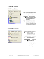
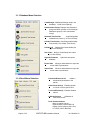
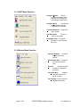
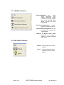
LiNC-EzTM
Programming Manual
33-10038-001
REV: G-pre
FOR iAM FIRMWARE VERSION GREATER THAN 4.00.00
FOR IQX FIRMWARE VERSION GREATER THAN 2.00.00
FOR NRX FIRMWARE VERSION GREATER THAN 3.00.00
PCSC
3541 Challenger St.
Torrance, CA 90503
Phone: (310) 303-3600
FAX: (310) 303-3600
www.1pcsc.com
Publication No. 33-10038-001-G
First Edition- Revision A: January 2001
Revision B: Dec 2001
Revision C: March 2002
Revision D: October 2002
Revision E: January 2003
Revision F: April 2003
Revision G: June 2005
Information in this manual is subject to change without notice and does not represent a
commitment on the part of PCSC. The software described in this manual is furnished under
a license agreement or nondisclosure agreement. The software may be used or copied only
in accordance with the terms of the agreement. No part of this document may be
reproduced, or transmitted, in any form or by any means, electronic or mechanical, including
photocopying, recording, or information storage and retrieval systems, for any purpose other
than specified in the agreement, without the express written permission of PCSC.
Windows is a registered trademark of the Microsoft Corporation.
© 2005 PCSC. All Rights Reserved.
Printed in the United States of America.
Published by PCSC
3541 Challenger Street
Torrance, CA 90503
Phone: (310) 303-3600
Publication No. 33-10038-001-G
Page ii of 55
LiNC-EZ iAM Installation Manual
33-10038-001-G
0.1 Release Notes for LincEz iAM v2.1.48
0.1.1 IMPORTANT COMPATIBLITY OPERATION:
LincEZ iAM Software is compatible with iAM v4.00.00 and newer versions. All PANELS or
IQX reference in this Installation Manual and on LincEZ iAM screen operations applies to all
iAM Controllers; unless otherwise indicated.
**WARNING** OLD LiNC-Ez VERSIONS ARE NOT COMPATIBLE WITH NEW IQX FIRMWARE.
UPGRADE LiNC-Ez SOFTWARE WHEN A NEW IQX OR NRX IS INSTALLED.
**WARNING** LiNC-Ez II IS NOT COMPATIBLE WITH IQX VERSIONS LESS THAN
2.00.00. YOU MUST UPGRADE OLD IQX FIRMWARE WHEN USING
LiNC-Ez II. FOLLOW IQX DOWNLOAD INSTRUCTION LOCATED IN ALL
ORIGINAL LiNC-Ez CD.
0.1.2 LiNC-Ez II Release Notes:
IQX Status screen shows the Door
Status
The IQX Status screen will indicate if the door
is locked or unlocked. Particularly useful when
AutoUnlock by Time Period is used.
Transaction Monitor can sort data in
ascending or descending order.
Highlight the column and right click. Select
Ascending or Descending.
Transaction Monitor will export to .XLS
file.
Highlight a column and right click mouse.
Select Export option.
In Download, panel firmware can be
Upgraded to IQX or NRX
This is to upgrade firmware application only,
NOT Parameter DATA.
Download can broadcast to all IQX
and/or NRX panels (concurrently)
After completing Parameter input, Broadcast
will update all panel application data.
Configure Doors now includes Counter
Properties
This is an Area Access Counter per panel (not
global). Used for garage or parking lots.
For NRX ONLYConfigure Doors has Configure Aux I/O
This controls the four I/O on the NRX. Inputs
are ORed to Output.
Serial Communication has communication
password.
This is to insure attaching to RS485 line,
access is not granted without proper password.
Do not lose password, cannot be retrieved.
Default password is LiNC-Ez.
Page iii of 55
LiNC-EZ iAM Installation Manual
33-10038-001-G
Release NOTE from LincEZ v2.1.48 to LincEZ v2.2.34
IAM control features were added to
The Zone, ZoneGroup, and Central Station
LincEZ Menu and Card Manager.
Configuration were added to Menu. Alarm
Control was added to each card in Card
Manager
IOX control features were added to
LincEZ Menu.
Input Configuration, Status and Calibration
were added to menu.
Single Client feature was added to
Company Info
Complete Remote Programming and reporting
communication can be establish via Client.
Remote access via Terminal Server to
RS485.
Communication via RS485 Terminal Server for
complete remote TCP/IP to Panel RS485 Loop.
Four Auto Unlock Time Periods added for
flexible time period unlock.
Allows different weekly day unlock schedule.
Repaired International Date Format
operation.
Day-Month-Year date format operate on all
date screens.
Broadcast will not operate on Panel
firmware x.00.77 or earlier.
Broadcast works only on iAM v4.01.14, NRX
v3.00.80, IQX v2.00.80 and/or IOX v5.00.08; or
newer.
Only single iAM will communicate via
RS232 LapLink Cable.
Any combination of iAM, NRX, IQX or IOX
requires RS485 communication.
Page iv of 55
LiNC-EZ iAM Installation Manual
33-10038-001-G
0.2 Table of Contents
LiNC-EzTM ........................................................................................................i
0.1 Release Notes for LincEz v2.1.61 ..................... Error! Bookmark not defined.
0.1.1 IMPORTANT COMPATIBLITY OPERATION: ........ Error! Bookmark not defined.
0.1.2 LiNC-EzTM Release Notes: ...................................... Error! Bookmark not defined.
0.2 Table of Contents .............................................................................................. v
1.0 Introduction..............................................................................................1
1.1 PC Requirements - LiNC-EzTM Software ........................................................... 2
1.2 Hardware Requirements ................................................................................... 2
2.0 Loading LiNC-EzTM ..................................................................................3
3.0 LiNC-EzTM Layout and Features .............................................................4
3.1 LiNC-EzTM Menus.............................................................................................. 5
3.1.1 File Menu Selection................................................................................................. 5
3.1.2 View Menu Selection............................................................................................... 5
3.1.3 Database Menu Selection ....................................................................................... 6
3.1.4 Panel Menu Selection ............................................................................................. 6
3.1.5 HOST Menu Selection............................................................................................. 7
3.1.6 Window Menu Selection.......................................................................................... 7
3.1.7 iAM Menu Selection ................................................................................................ 8
3.1.8 HELP Menu Selection ............................................................................................. 8
3.2 LiNC-EzTM Toolbar ............................................................................................ 9
4.0 LiNC-EzTM Programming .......................................................................10
4.1 Configuration Wizard....................................................................................... 10
4.1.1 Company Information ............................................................................................ 10
4.1.1a New/Open Client Feature.................................................................................... 11
4.1.2 Door Names .......................................................................................................... 12
4.1.3 Door Assignments ................................................................................................. 12
4.1.4 Daylight Savings.................................................................................................... 13
4.2 Door Configuration .......................................................................................... 14
4.2.1 Door Properties ..................................................................................................... 14
4.2.2 Access Parameters ............................................................................................... 16
4.2.3 Readers ................................................................................................................. 17
4.2.3.1 Entry/Exit on a Single Door............................................................................ 17
4.2.3.2 Reader Configuration Screen ........................................................................ 18
4.2.4 Counter Properties ................................................................................................ 19
4.2.5 Configure Aux I/O [ for NRX Only ] ....................................................................... 19
4.3 Standard Time Periods.................................................................................... 20
4.4 Holiday Time Periods ...................................................................................... 21
4.5 Holiday List...................................................................................................... 22
4.6 Authorization Groups....................................................................................... 23
4.7 Card Manager ................................................................................................. 24
4.7.1 Adding Cardholders through the Overview and Detail Tabs................................. 24
4.7.2 Alarm PIN User Number........................................................................................ 26
4.7.3 Bulk Change.......................................................................................................... 27
4.7.4 iAM ........................................................................................................................ 28
4.7.4.1 Setting a iAM access card PIN code: ............................................................ 28
4.7.4.2 Establishing an Alarm Company Guard Card................................................ 29
Page v of 55
LiNC-EZ iAM Installation Manual
33-10038-001-G
4.7.4.3 iAM Zone Configuration ................................................................................. 29
4.7.4.4 Creating Zone Groups ................................................................................... 30
4.7.4.5 Calibrate or Suppress Alarm Zones............................................................... 30
4.7.4.6 Central Station Configuration......................................................................... 31
4.8 Import and Export............................................................................................ 32
4.8.1 Import .................................................................................................................... 32
4.8.2 Export .................................................................................................................... 33
4.9 Download/Broadcast ....................................................................................... 34
4.10 Transaction Monitor....................................................................................... 35
4.11 Site Codes ................................................................................................. 36
4.12 Generating Reports ....................................................................................... 37
4.13 iAM Security Management ............................................................................ 38
4.13.1 Configuring Alarm Zones using LiNC-EzTM ......................................................... 38
4.13.2 Setting the Parameters for the Central Station Notification ................................ 39
4.13.3 Configuring the Zone Groups.............................................................................. 40
4.13.4 Calibrating a Supervised Alarm Zone ................................................................. 41
5.0 Remote Modem Communication Setup (optional)..............................42
5.1 Single Modem; Multiple Panel (SMMP)........................................................... 42
5.1.1 Panel Loop ............................................................................................................ 43
5.2 Modem SMMP Programming .......................................................................... 43
5.2 Modem SMMP Programming .......................................................................... 44
5.2.1 Computer Configuration ........................................................................................ 45
5.2.2 Modem Configuration ............................................................................................ 46
5.2.3 LiNC-EzTM Panel Communications ....................................................................... 48
5.2.4 iAM Modem Communication Setup....................................................................... 49
6.0 Appendix iAM Startup & Default Parameter ........................................55
End of Manual ............................................................................................................ 56
Page vi of 55
LiNC-EZ iAM Installation Manual
33-10038-001-G
1.0 Introduction
Welcome to the LiNC-EzTM Installation and User manual. The LiNC-EzTM access control and
alarm system is the best and most cost-effective system on the market for the small to mid-size
facilities. This manual will describe the best method for loading LiNC-Ez onto your system and
configuring the access control and security measures capabilities. The manual is designed in
the the following order:
1.0 Introduction..............................................................................................1
2.0 Loading LiNC-EzTM ..................................................................................3
3.0 LiNC-EzTM Layout and Features .............................................................4
4.0 LiNC-EzTM Programming .......................................................................10
5.0 Remote Modem Communication Setup (optional)..............................42
6.0 Appendix iAM Startup & Default Parameter ........................................55
It is assumed that prior to loading LiNC-Ez, the physical layout of the IQX, NRX and iAM,
readers and assorted I/O’s of the LiNC-Ez system have been determined.
1.1 PC Requirements - LiNC-EzTM Software
To install LiNC-EzTM for Windows- 2000/XP, the following requirements must be met:
•
•
Windows 2000 or Windows XP must be installed on the host computer.
User must have knowledge of mouse and keyboard use in the Windows 2000/XP
environment.
1.2 Hardware Requirements
Compare your computer hardware features to the chart below, which lists the requirements for
proper operation of LiNC-EzTM. If you have any questions regarding your computer
configuration, call PCSC Application Engineering at (310) 638-0400, ext. 1694.
Hardware Item
Minimum Requirement
CPU
IBM PC or equivalent: Pentium (minimum 800 MHz for Host),
Windows 2000 or Windows XP.
RAM
256 MB
Hard Drive
8 GB
Diskette Drive
3.5 in., 1.44 MB
CD RW Drive
24X CD RW drive
Monitor
SVGA, 640 x 480, 16 color
Keyboard
AT type
Mouse,
WINDOWS compatible Bus or PS2 Mouse
Parallel Port
LPT1
Serial Port
One DB9 COM RS-232 dedicated for LiNC-EzTM
U.P.S.
Uninterruptible Power Supply 420 VA for PC and monitor
Page 2 of 55
LiNC-EZ iAM Installation Manual
33-10038-001-G
2.0 Loading LiNC-EzTM
Close all programs, including those which default to COM1 (i.e. - PDA communication device,
Palm Pilot Link, serial mouse, etc.). Also, disable any virus protection software until installation
is complete.
Install the LINC-EzTM program CD into the CD-RW drive. The InstallShield Wizard should load
automatically once.
NOTE: If the CD-ROM doesn’t automatically launch, use the following steps to
launch the InstallShield Wizard.
1. Enter Windows to find out what is the letter name of the CD-ROM drive.
2. Click on the Start Menu and then select Run.
3. Type in the Letter of the CD-ROM drive followed by “:\setup.” Click OK.
This will start the loading process.
The InstallShield Wizard takes over the loading process and will guide you through the rest of
the process.
1. Enter your Name and Company Name and click on Next.
2. Check the appropriate language you wish to
operate LiNC-EzTM.
3. Install will automatically load the LiNC-EzTM
into the Program Files folder. Redirect if
necessary.
4. Click Finish to complete the process and
restart your computer.
Page 3 of 55
LiNC-EZ iAM Installation Manual
33-10038-001-G
3.0 LiNC-EzTM Layout and Features
Once you have finished the installation process, a LiNC-EzTM shortcut will be placed on your
desktop.
Double-click on the LiNC-EzTM shortcut. LiNC-EzTM will open to it’s main page.
NOTE: Section 3.0 is devoted to describing the basic layout of the LiNC-EzTM program
and its different sub-menus. To continue with the programming of LiNC-EzTM,
please proceed to Section 4.0.
Top Menu
Icon Menu
View/Options Menu
Alarm Indicator
Panel Status
Page 4 of 55
LiNC-EZ iAM Installation Manual
33-10038-001-G
3.1 LiNC-EzTM Menus
3.1.1 File Menu Selection
Print
Prints contents of Transaction
Monitor, Reports, Card
Manager & Holiday List to
select printer
Print Setup
Allows operator to
select a printer on the system
and control the properties of
the printer
Exit
Causes LiNC-Ez to cease
operating. By doing this you
will cause the controllers to
operate in a standalone mode
until the program is restarted.
3.1.2 View Menu Selection
History Transactions Allows the
operator to view all
transactions as they are
received from the panels.
Show Panel Status
View status
of all panels & Door Lock
Status on the system.
Predefined
Display Reports
reports available to the
operator:
• Card Holder Report
• Holiday List
• Holiday Time Period
• Standard Time Period
• History Log
Page 5 of 55
LiNC-EZ iAM Installation Manual
33-10038-001-G
3.1.3 Database Menu Selection
Card Manager Add/Delete/Change cards in the
database [ 1-3,000 Card Capacity]
Authorization Groups Displays all authorization
groups and allow operator to View/Change/ Add/Delete groups.[1-255 Authorization
Group]
Standard Time Periods
View/Change/Add
standard time periods. [1-32 Time Periods]
Holiday Time Periods View/Change/Add holiday
time periods [1-32 Holiday Time Period]
Displays the entered holiday list
Holiday List
[Up to 64 Holidays]
Site Codes Ability to View/Change site codes
[1-16 Site Codes]
Organize Database
database
Optimizes and repairs
Export Data
Allows an administrator to export the
current LiNC-Ez parameters
Import Data
Allows an administrator to import the
current LiNC-Ez parameters
3.1.4 Panel Menu Selection
Download Data to the IQ
Initiate a
download of parameters to the
panels
Unlock/Lock Door(s) Enables operator
to unlock or lock a specific door.
Turn On/Off Alarm(s) Enables/ disables
alarms
Calibrate Sensors
Calibrates all
supervised circuits.
Panel Communications
ability to change and set
communication via serial RS-232
(COM), modem (dial-up phone line)
or TCP/IP (LAN or Ethernet).
Page 6 of 55
LiNC-EZ iAM Installation Manual
33-10038-001-G
3.1.5 HOST Menu Selection
Configure Wizard
Sets up
company information, Door
Names, Door Assignments
and Daylight Savings times
Configure Doors
View/change
Door Properties, Access
Parameters and Readers.
Turn Host Alarm Off
alarm On/Off
Toggles the
Test Host Alarm
Tests the
alarm on the system
Show/Hide Poller - Turns poller
information in LiNC-Ez task
bar on/off.
3.1.6 Window Menu Selection
Close All Windows
Closes all
windows previously
opened.
Reset Default Sizes
Restores
all windows to default
sizes.
Cascade
Arranges selected
windows in a cascaded
orientation.
Tile Horizontally
Arranges
selected windows one
above the other.
Tile Vertically Sets up selected
windows side by side.
Page 7 of 55
LiNC-EZ iAM Installation Manual
33-10038-001-G
3.1.7 iAM Menu Selection
Zone Configuration
sets
Alarm
Zones
parameters,
Zone
Names, Supervised Zones,
Latched Alarm points, Bypass
zone point, Common Area
Armed Override and Zone
Delay period.
Zone Group Configuration
creates
definition of each Zone Group.
Central Station Configuration Sets the
parameters for contacting the
Central Station.
Calibrate or Bypass Alarm Zones
Allows the user the ability to
calibrate or bypass individual
alarm zones.
3.1.8 HELP Menu Selection
Page 8 of 55
Manual
Opens a pdf version of this
manual
About
Provides information about
Author and Version of the
program.
LiNC-EZ iAM Installation Manual
33-10038-001-G
3.2 LiNC-EzTM Toolbar
Print Form
Transaction History
Show Panel(s) Status
Configuration Wizard
Configure Door Parameters
Card Management Tool
Authorization Groups
Standard Time Periods
Unlock/Lock Door(s)
Reset Windows to Default Sizes
Close All Windows
Author and Version
More Tools
Page 9 of 55
LiNC-EZ iAM Installation Manual
33-10038-001-G
4.0 LiNC-EzTM Programming
4.1 Configuration Wizard
Once the initial loading of LiNC-EzTM is complete, the LiNC-Ez Configuration Wizard will
determine the communication method, basic operating setup and will download the default
database and ready to run with the default data. And reference the reader to where to jump to
initiate a full data download.
4.1.1 Company Information
1. Enter: Your Name
Company Name
Address
Phone number
2. Select Apply or OK. Select Clear to begin over again.
3. The Regional Setting will adjust Holiday List for LiNC-EzTM.
4. Password will protect from unauthorized access to LiNC-EzTM Software. Press
Password, in the password screen type in your password, twice.
5. The next time LiNC-EzTM is launched, the password will be required. To remove
password: follow the same procedure to Add, but enter a blank field.
Note: Do not forget the password. You can NOT retrieve password.
You must reload LiNC-Ez if the password is lost.
Page 10 of 55
LiNC-EZ iAM Installation Manual
33-10038-001-G
4.1.2 New/Open Client Feature
1.
2.
3.
4.
To create New Client, select New Client button at Configuration Wizard.
Type the name of the New Client and click Open.
To open a client, select Open Client button at Configuration Wizard.
Select the client and click Open.
NOTE: To change configurations of newly created client, close and reopen LiNC-EzTM. This
will default the settings of the software and will be ready to be changed. It is mandatory
to close and reopen LiNC-EzTM whenever switching between clients, for changes to be
made to the appropriate client.
Page 11 of 55
LiNC-EZ iAM Installation Manual
33-10038-001-G
4.1.3 Door Names
1. Enter the number of panels connected
together on this system.
IMPORTANT
This indicates how
many panels to look for.
2. Add or Delete door names as they will
be used at this site.
3. Select Apply
This will create the list of selections that will be
used on the next screen.
4.1.4 Door Assignments
1. For each door on the system,
select the name of the door by
clicking the down pointer and
highlighting the name of the
door assigned to each panel.
2. Select Apply or OK to store the
names
Page 12 of 55
LiNC-EZ iAM Installation Manual
33-10038-001-G
4.1.5 Daylight Savings
The daylight savings times have been factory set until 2012. To correct or change any of the
default dates you can change the Start or End dates in the Daylight Savings Time field.
Setting the No Daylight Savings option will cause the program to ignore Daylight Savings.
Page 13 of 55
LiNC-EZ iAM Installation Manual
33-10038-001-G
4.2 Door Configuration
IMPORTANT:
For all
Configure
Door tabs,
select the
appropriate
panel.
4.2.1 Door Properties
This set of screens sets up the operating parameters for all of the access controlled doors. The
factory default set up for doors will show all items selected except Contact Supervised and
Request to Exit Supervised.
Set up the Door Properties as follows:
Contact Used
Check this box if door contacts are to be monitored to audit
door open or closed status.
Contact Supervised
Check if contact circuit is monitored for tampering using 4 state
supervision.
Request to Exit Used
Check box if REX (Request to Exit) has been installed and is
to be used to allow for push button opening of a controlled
door.
Request to Exit Supervised
Check box if the REX circuit is monitored for tampering using 4
state supervision.
Valid Card Resets Door Forced Open Alarm Check this box if you want any local alarm that
is sounded to be turned off by the first valid card that is read
after the alarm is triggered.
Enable Door Left Open Alarm Shutoff Time Select this box to set up the amount of time
that the alarm will be bypassed before sounding.
Page 14 of 55
LiNC-EZ iAM Installation Manual
33-10038-001-G
Alarm Shutoff Time
Used to set the amount of time to shunt the alarm when the
Enable Alarm Shutoff Time box has been selected.
Factory Defaults
Selecting this will cause the program default values to be
entered into the door configurations.
Page 15 of 55
LiNC-EZ iAM Installation Manual
33-10038-001-G
4.2.2 Access Parameters
The access parameters set up the length of time doors are unlocked and allowed to be open
before any action is taken to report alarms.
Set up the Access Parameters as follows:
Unlock Time
The amount of time in seconds that the door lock is energized
(door unlocked).
Open Time
The amount of time that the door can remain open prior toan
alarm sounding if an alarm has been selected for this door.
Long Unlock Time
The amount of time specified for certain cardholders needing
extra time to open a door.
Long Open Time
The amount of extended time that the door will remain open
until an alarm is triggered in those cases where additional time
is required to get through the door. Maximum setting is 255
seconds.
Auto Unlock Time Period
The duration which a door will automatically unlock. Select the
time period by clicking on the down arrow and highlighting the
desired time period.
Card Unlock
Auto Unlock Time Period starts when first Authorized Card is
presented during the Auto Unlock Period.
Card Lock
Locks door during AutoUnlock Period when Authorize Card is
presented.
Note:
On a Holiday time periods, if Auto Unlock Time Period is programmed,
Auto Unlock must always be Authorized with a valid card.
Page 16 of 55
LiNC-EZ iAM Installation Manual
33-10038-001-G
4.2.3 Readers
This screen is used to configure each of the readers. LiNC-EzTM is compatible with a wide
range of proximity readers (such as the PR-732 included in the LiNC-EzTM Installation kit),
proximity-keypad readers, and magstripe readers.
Select the reader by checking the box next to the reader name and press Config button to
bring up the Reader Configuration screen.
4.2.3.1 Entry/Exit on a Single Door
LiNC-EzTM has the ability for entry/exit capability on a single door. By installing readers on
either or both sides of an access point, LiNC-EzTM can be set up to monitor entry and exit from
a single room.
In the Reader Config screen, in the Assignment box, a reader can be set to monitor either
Entry or Exit. In an access point with two readers, Reader A may be set for Entry and Reader
B set for Exit (or vice versa).
Page 17 of 55
LiNC-EZ iAM Installation Manual
33-10038-001-G
4.2.3.2 Reader Configuration Screen
Reader Description-
In this screen you will see the Door # and name assigned to that door.
Reader Type
Select the down arrow and highlight the reader type being used with
this door position on this panel. (This area has been expanded for more reader types.)
NOTE
If card is selected with Keypad, all cards will default to 0000 as the pin
number.
Anti-Passback Time Select the amount of time to pass before a card can be used again at
this reader. Select Apply or OK to activate and save your selections.
NOTE
This is to prevent someone from passing his or her card back to another user
to allow entry into the door or gate.
Entry/Exit Assignment
allows access to area controlled by a single panel (two doors)
only.
Important Inside the Reader Configuration window, the proper door must be highlighted
when antipassback is required. This will establish the highlighted door as
Entry; the second door of this panel will automatically be the Exit.
The operation of Entry/Exit is when a card is authorized to the Entry reader then it must be
authorized to the Exit before entry is granted again.
Note
Page 18 of 55
Entry/Exit is per one panel only. It is not global within a system of panels.
The EXIT will always be granted.
LiNC-EZ iAM Installation Manual
33-10038-001-G
4.2.4 Counter Properties
All Readers, Rex, and door
Contacts can be applied to
Increment or Decrement
area inputs.
The High Count will turn on
Local Alarm. Maximum
count will DISABLE door
relays.
NOTE: Area Counter is controlled by only one panel. Each area is controlled one panel, not
multiple panels.
4.2.5 Configure Aux I/O [ for NRX Only ]
Select Inputs, which are
Supervised
Check which Inputs are
AND-ed together to turn
ON Output.
Select NRX only
Page 19 of 55
LiNC-EZ iAM Installation Manual
33-10038-001-G
4.3 Standard Time Periods
This screen brings up the factory default time periods.
To change the times within the periods, highlight the Standard Time Period you want to change
and:
1. Left-click on the red bar at the top of the screen at either end and adjust its length to your
requirements. This will automatically update the Start and End columns as you change the size
of the red bar.
OR
2. Double click a Start/End and use the up/down arrows in the box to change the start and end
times.
3. Select Apply or OK to save your data.
NOTE NEVER and ALWAYS are factory defaults and cannot be altered.
Page 20 of 55
LiNC-EZ iAM Installation Manual
33-10038-001-G
4.4 Holiday Time Periods
Holiday Time Periods are the controlling times for the corresponding Standard Time Periods
and are active on Holidays only.
All Holiday Periods are off until you program them for Holiday use (except ALWAYS)
Normal Work Week will not have access during Holiday unless Holiday Schedule gives access.
NOTE Holiday time periods start at 12 midnight.
Use the same steps to change the Holiday Periods as you did above in the Standard Time
Periods.
NOTE NEVER and ALWAYS are factory defaults and cannot be altered.
Select Apply or OK to save your data.
Page 21 of 55
LiNC-EZ iAM Installation Manual
33-10038-001-G
4.5 Holiday List
The Holiday List determines those days where the Holiday Time Periods are to be invoked.
Holidays should be added by selecting the appropriate month, clicking on a day, and filling in
the information in the Holidays column.
Select Apply or OK to save your entries
Page 22 of 55
LiNC-EZ iAM Installation Manual
33-10038-001-G
4.6 Authorization Groups
An Authorization Group (AG) is used with the cardholder record. An AG is a list of readers
and the time period in which these readers are accessible. Each cardholder can be assigned 4
Authorization Groups. When a card is presented to the reader, the panel checks the
cardholders four AG and verifies that the card reader is valid within one of them. If the reader is
not found in any of the Groups assigned to the cardholder, the system will deny access due to
“Invalid Reader”. When a reader is found within the AG, the current time is checked with the
Time Period associated with the AG. If the time is not valid, an “Invalid Time Period”
transaction will be generated and access will be denied.
To set-up authorization groups:
1. Click the Authorization Group you are going to define.
2. Use the Time Period down pointer, select the time period to assign. Clicking on the time
period you will notice that the time period next to the ID will be changed accordingly.
3. In the areas below, select from the Doors Available to be allowed for the current group and
use the transfer arrows to move those doors into the Doors Assigned column.
4. Select Apply or OK to make the selection active.
Page 23 of 55
LiNC-EZ iAM Installation Manual
33-10038-001-G
4.7 Card Manager
4.7.1 Adding Cardholders through the Overview and Detail Tabs
1. To Add Cardholders to the database, click Database, then Card Manager.
2. The Card Manager Screen appears:
3. Click on the card number
that you want to enter.
4. Click on the Detail tab to
bring up the Detail
screen.
5. Enter the Name,
Department, Company
Name and Address.
6. Enter Phone number
and extension if
appropriate.
7. Set the Activation Date
NOTE
The Activation Date
defaults to today’s date. If
the card activates on a
different date than today
then change the date.
NOTE
All cards have a default
expiration date of ten (10)
years from issuance.
Page 24 of 55
LiNC-EZ iAM Installation Manual
33-10038-001-G
8. Select an Authorization Group(s) for the cardholder.
9. Set Card Active to activate the card.
NOTE A card will not immediately activate if the activation date is set for the future.
10. Select Long Access to increase the amount of time the door can stay open without
triggering an alarm.
11. Picture will add JPEG Picture File to card detail.
NOTE
Must apply before moving to the next card detail, to save any changes.
12. Click on the right > of the Change Record tool to apply these entries and go to the
next record.
13. Return to the Overview screen to verify that the card you entered has been properly
accepted.
Page 25 of 55
LiNC-EZ iAM Installation Manual
33-10038-001-G
4.7.2 Alarm PIN User Number
Alarm Company Employee is a card for the alarm company. When selected card will not
open or arm or disarm system unless an alarm has occurred. When system is normal, card
presented to read will report to Central Station.
Alarm PIN User Number is first two digits of PIN number.
Alarm Zone Group is group armed or disarmed by PIN user.
Keypad PIN is last 2-4 digits of PIN number. Combine Alarm PIN User Number with Keypad
PIN for user PIN number, i.e.: 01 and 11 pin number is 0111.
Page 26 of 55
LiNC-EZ iAM Installation Manual
33-10038-001-G
4.7.3 Bulk Change
Bulk Change allows data to be populated into a range of cards in bulk rather than changing
each record individually.
Enter the data that will appear in each of the card records and then use the Batch Change
button to set up the range of cards to be affected.
NOTE You must download to panel before information is operational.
Page 27 of 55
LiNC-EZ iAM Installation Manual
33-10038-001-G
4.7.4 iAM
The iAM screen allows up to 99 individual cards to be specified for iAM alarm code access
within particular zones using a separate PIN number. Please note that only the reader on the
iAM panel can disarm an iAM panel. A card can be defined to disarm both a common area
(such as a lobby) and another area/areas.
Each Card User can establish a six-digit iAM access code comprised of:
• 2-digit User Number
• 4-digit PIN number
NOTE: The keypad MUST be used to re-arm the panel. Therefore, PIN numbers MUST be
setup. Up to 4 keypads can be attached to the system.
4.7.4.1 Setting a iAM access card PIN code:
1. From the top menu, click on Database / Card Manager or on the Card Manager
icon.
2. Specify the Card ID that will be given the iAM access code.
3. Determine the Alarm PIN User Number from the dropdown box (to a maximum 99
users).
4. Determine the Alarm Zone Group that the cardholder will be a member. See
section 4.13.3 for more information on the proper creation of Alarm Zone Groups.
5. Press the OK button to save the settings and close the window.
Page 28 of 55
LiNC-EZ iAM Installation Manual
33-10038-001-G
4.7.4.2 Establishing an Alarm Company Guard Card
In the event of an alarm an Alarm Company Guard will be able to do the following:
• Ability to “register” at the customer site
o Card transaction recorded and sent to Central
o No Access granted
• Ability to Gain Access during an Alarm Condition
To establish a card to be a specific Alarm Company Guard card, select the Alarm Company
Employee checkbox. Follow the instructions for 4.7.1 as stated to finish the card programming.
4.7.4.3 iAM Zone Configuration
Zone Name
Supervised
Latched
Inverted
Pre-Alarm Delay
Used
Event Codes
Page 29 of 55
identifies zones. Name can be changed here.
must be selected for zone points with supervising resistors. Note:
changing DRSTS-Door will change door supervised status in Configure
Doors\Door Properties.
will latch each zone violation. Latch will report the violation only once.
will invert the zone point normal condition.
will allow seconds of delay before zone violation will be reported.
will indicate if Zone has been entered in Zone Group. This is
automatically done.
are the codes sent to Central Station when Alarm, Shorted, Cut or
Bypassed violation occurs.
LiNC-EZ iAM Installation Manual
33-10038-001-G
4.7.4.4 Creating Zone Groups
1. Select ZoneGroupID, then
select from Zones
Available and move to
Zones Assigned.
2. Do this for each
ZoneGroupID required.
3. Apply when complete.
4.7.4.5 Calibrate or Suppress Alarm Zones
Calibrate Zones
will calibrate supervised zone points. Select and Apply.
Bypass Alarm Zones will suppress zone reporting for one Alarming.
Page 30 of 55
LiNC-EZ iAM Installation Manual
33-10038-001-G
4.7.4.6 Central Station Configuration
Panel Account #
the unique number for iAM sent to Central Station.
Max # of Tries to Send Alarm (1-255) will set number retries of alarm to Central Station once
the iAM is communicating with Central Station. If the iAM and
Central Station is online but Central Station does not
acknowledge the alarm after set retries, the iAM will consider
alarm sent.
Seconds Between Calls
sets seconds for dialup. When iAM encounters an alarm it will
delay for set number of seconds before dialing Central Station.
Seconds to Wait After CS Busy sets number of seconds to redial if Central Station line is
busy.
Alarm Buffer Trigger Level
sets the number of Alarms before iAM overrides the Seconds
Between Call delay to dials the Central Station.
Duress PIN
number added to end of User PIN to send silent alarm to
Central Station.
Central Station Phone #
the Central Station number.
Admin PIN
number to enter Administration features at keypad on iAM.
Seconds of No CS Response Timeout sets the seconds to hang up if Central Station does
not communicate.
Common area Exit Delay
sets time to leave and secure building.
Common Area Entry Delay
sets time to delay before reporting alarm if no pin number
disarms iAM.
Bell Duration
sets length of Bell output A. Zero for never; 1-254 seconds or
255 forever.
Minutes Between Bell Test
monitors Bell condition.
Minutes Between Line Test
monitors phone line condition.
Minutes Between CS Callback sets the regular time period iAM call into Central Station.
Page 31 of 55
LiNC-EZ iAM Installation Manual
33-10038-001-G
4.8 Import and Export
4.8.1 Import
In the event that an administrator needs
to import card information from a
separate LiNC-EzTM system, the Import
feature will override the existing LiNC-Ez
TM
database.
1. By selecting Import from the
database menu, the Import window
appears.
2. Select the LiNC-EzTM features that
you wish to import (see below).
3. Click the OK button. Save In window
will appear with the title ”Choose a
database to backup to” with the
default name Export.mdb.
4. Choose a database file to restore
from and click the Save button.
NOTE Importing a new database file will OVERWRITE the current database
Page 32 of 55
LiNC-EZ iAM Installation Manual
33-10038-001-G
4.8.2 Export
LiNC-EzTM has added a new feature that allows an administrator to export
the existing LiNC-EzTM database. This is beneficial for archiving.
Emergency back-up, and for transferring the database to another
computer.
1. By selecting Export from the database menu, the Export Data window appears.
2. Select the LiNC-EzTM features that you wish to export to a different copy of LiNC-EzTM (see
below). Click the OK button.
3. A Save As window will appear with the title “Choose a database file to back up to” with
the default name of Export.mdb. Choose an appropriate location for the exported
database, and click the Save button.
NOTE Export you parameters regularly. This information is necessary for
recovery.
Page 33 of 55
LiNC-EZ iAM Installation Manual
33-10038-001-G
4.9 Download/Broadcast
NOTE
Cards will not operate in the panel system until the first download of the
LiNC-EzTM system
Once the parameters have been set up, they are downloaded from this screen.
1. Select files to download
2. Select Download All Panels or Broadcast to All Panels.
3. Click the Apply button.
During the download, a progress bar appears near the bottom of the screen to give you the
current status. Broadcast to All Panels will download all panels on a loop.
To set Factory Defaults:
1. Select the File menu item
2. Click the Factory Default button. Only use this button when you want return to Factory
Default. It will not download to panel.
3. You must exit Linc-Ez, then re-enter for defaults to take effect.
NOTE Firmware Download allows upgrade for new panel application firmware, not
to download parameters.
Page 34 of 55
LiNC-EZ iAM Installation Manual
33-10038-001-G
4.10 Transaction Monitor
The Transaction Monitor screen presents each of the transactions occurring on the system.
Check the Browse box to prevent the screen from updating while you scan through entries.
Archive the transactions by clicking the Archive button. You will be asked for the number of
days prior to today to archive. To archive the last week, enter 7; to archive the last month, enter
30. Archive will remove transaction from LincEZ. Archive located in CSV file, compatible with
spreadsheet or database.
NOTE When Transaction Monitor refreshes slow, Archive the Transaction
Monitor.
Select OK to close this screen.
Page 35 of 55
LiNC-EZ iAM Installation Manual
33-10038-001-G
4.11 Site Codes
A Site Code (also known as a Facility Code) allows independent operation of each LincEZ
system. In a multi-tenant building with multi-LincEZ is they would run completely independent.
The Multi-Site Code feature allow up to 16 site code on one LincEZ. This has the added benefit
to program only one LincEZ with or without Site Code separation.
1. Select Site codes from the Database top menu or vertical menu selection.
2. Highlight --- (dashes) in Site Code # column, and type in site code number.
Note
The original Site Codes is located on the CD and will automatically load upon
installation.
3. To finish the job, select Apply and OK
Page 36 of 55
LiNC-EZ iAM Installation Manual
33-10038-001-G
4.12 Generating Reports
There are five reports that can be printed in LiNC-EzTM.
• Card Holder Report
• Holiday List
• Holiday Time Period
• Standard Time Period
• History Log
1. Select Reports from the View top menu or vertical menu selection.
2. Select the report you wish to print by highlighting it with the mouse.
3. Now select the sorting mode you want.
4. Select Preview to view the report on the screen before printing it out.
5. Selecting the Print button after
previewing will show you a sample page of
the report on the screen before printing it
out
6. Click on the printer icon to send the
report to the default printer on your system.
Page 37 of 55
LiNC-EZ iAM Installation Manual
33-10038-001-G
4.13 iAM Security Management
Each iAM panel has 21 inputs and 99 zones that can programmed using LiNC-EzTM . This
section discusses the proper method of Configuring Alarm Zones and Alarm Groups and how to
set the Central Station
4.13.1 Configuring Alarm Zones using LiNC-EzTM
Each Zone is comprised of two general features, the Selectable Options and the Alarm Event
codes.
The Selectable Options are the:
• Zone Name
• Supervised
• Latched
• Inverted
• Pre-Alarm Delay
LiNC-EzTM automatically establishes default Alarm Event codes:
•
•
•
•
Alarm
Shorted
Cut
Bypassed
131 Perimeter Alarm
137 Tamper
137 Tamper
570 Zone/Sensor/Bypass
However, other event codes can be substituted for the default codes through the dropdown
boxes.
Page 38 of 55
LiNC-EZ iAM Installation Manual
33-10038-001-G
4.13.2 Setting the Parameters for the Central Station Notification
LiNC-EzTM connects to the Central Station through the built-in modem on the iAM panel. In
order to contact the central station, the phone number needs to be programmed into LiNCEzTM.
1.
2.
3.
4.
From the top menu, press IAM / Central Station Configuration.
Enter the phone number for the Central Station.
Press the Apply button to save the change.
If you wish to change any of the additional settings for contacting the Central Station,
do so at this time.
5. Press the OK button to save your settings and close the Central Station
Configuration window
Page 39 of 55
LiNC-EZ iAM Installation Manual
33-10038-001-G
4.13.3 Configuring the Zone Groups
A Zone Group is a combination of different zones identified by a common name and used for
ease in programming.
Each Zone Group can hold a selectable number of Zones. LiNC-EzTM comes with a default
setting for the first three Zone Groups:
• Zone Group 0 – No Zones
• Zone Group 1 – Common Area
o Bell Output
o Door Status
• Zone Group 2 – Alarm Zones 1-8
To create a custom Zone Group:
1. From the top menu, select iAM / Zone Group Configuration
2. Select the appropriate Zone Group (3-99) that you wish to program.
3. In the Zone Available window, select the Zones to be assigned to the Zone group. Use
the CTRL button to highlight individual zones.
4. Press the arrow button to move the selected zones to the Zones Assigned window.
5. Press the Apply button to save the selection or press the OK button to save the
selection and close the window.
Page 40 of 55
LiNC-EZ iAM Installation Manual
33-10038-001-G
4.13.4 Calibrating a Supervised Alarm Zone
Alarm Zones are system Defaulted to “Non-Supervised” from the Factory. LiNC-EzTM has the
ability to create a Supervised Alarm Zone. However, you must define a Zone for “Supervision”
before Calibrating can be accomplished. Also, PCSC approved End of Line resistors must be
installed to provide accurate monitoring. Only twenty zones can be programmed.
In order establish supervision, a Zone needs to be selected for supervision via the Zone
Configuration screen.
1. From the top menu, select iAM / Zone Configuration.
2. Find the zone(s) that is to be supervised and select the checkbox in the Supervised
column.
3. From the top menu, select iAM / Calibrate or Suppress Alarm Zones.
4. Select the zone(s) that is to be calibrated.
Press the Apply button to save your changes, or press the OK button to save your changes and
exit the window.
Page 41 of 55
LiNC-EZ iAM Installation Manual
33-10038-001-G
5.0 LiNC-Ez Communication
5.1 Single Modem; Multiple Panel (SMMP)
COM1
CABLE P/N; 04-10291-001
LiNC-EZ
PCSC
DB9
Cross-Over Cable
DB25
LINE
PWR
ON
56
US ROBOTICS MODEM
Null Cable
CABLE P/N; 04-10344-001
DB25
LINE
DB9
PWR
ON
3
RS485
CONVERTER
56
US ROBOTICS MODEM
IQX 2
IQX 1
+
COM
Page 42 of 55
LiNC-EZ iAM Installation Manual
33-10038-001-G
At the LincEZ PC
A standard modem cable (p/n: 04-10291-001) is connected between PC DB9 - Com1 to
modem DB25, and the modem to the telephone line (see diagram). Follow all modem
installation instruction for proper handling and power requirements.
NOTE For proper function, please use a single pair of external PCSC
US Robotic Modems 33K or greater w/ Dipswitch (PCSC model #
MODAEXT).
Set PC modem DIP Switch:
5 – Up (Auto Answer on First Ring)
6 – Up (Carrier Detect Normal)
All other DIP Switch OFF
PC modem setup:
1. Power modem; reboot the PC System. Install New Hardware Found; select Standard
Modem driver
2. After the Standard Modem has been installed, go to the Control Panel \ Modem \
Properties and set parameter as:
Data bits – 7
Parity – odd
Stop bits – 1
No Flow Control
“Wait for dial tone before dialing” checked
5.1.1 Panel Loop
The Panel Loop can handle 1-32 panels. All panels must be wired as directed in installation
manual. RS 485 wiring is Plus (+) to Plus (+); Minus (-) to Minus (-); Com connected all Com;
All Shield connected to ONE earth ground. The Panel Loop modem has special cable (p/n #
04-10344-001) to RS485 converter. Attach Panel Loop phone line to modem.
Set Panel:
All panels in the loop must be set to modem mode. On Panel PCB set dip switch #8 – ON
(toward LED) The dip switch #8 set the panel in modem mode.
Set Loop modem DIP Switch:
3 – Up (Suppress Results Codes)
5 – Up (Auto Answer on First Ring)
6 – Up (Carrier Detect Normal)
All other DIP Switch OFF
WARNING:
Don’t confuse the settings of DIPswitch on modem and the panel.
They are not the same.
Page 43 of 55
LiNC-EZ iAM Installation Manual
33-10038-001-G
5.2 Modem SMMP Programming
Pull down from Top Menu Panel and select Panel Communications. In Default
Communication Type pull down select Modem and Apply.
In TAPI/Modem enter:
Host Primary Phone
#
-
First phone number IQ Loop will dial for alarm condition
Host Secondary
Phone #
-
If Primary Host line does not engage then Secondary phone
number will be called. If no Secondary line available, then reenter
Primary Phone number. If no Secondary Phone number present
then phone line will incorrectly dial second number.
Loop Phone
Number
-
Enter Phone number for panel Loop.
Dial button
-
Will dial Loop Phone number.
Hang Up button
-
Hang up manual the Loop Phone number
Max Dial Tries Per
Connection
-
Enter Maximum number of tries to connect
Minutes Between
Retires
-
Enter number of minutes between retries.
Schedules Call
Interval Minutes
-
Enter number of minutes between Schedule calls on Schedule
days.
Seconds of No
Traffic Limit
-
Time before phone call attempted.
Page 44 of 55
LiNC-EZ iAM Installation Manual
33-10038-001-G
5.2.1 Computer Configuration
In order to have modem communication, COM 1 of the computer must be configured.
1. Right click on My Computer icon and select Properties. In the pop up window, select
the Hardware tab and click on Device Manager.
2. Find and open Ports and double click on Communications Port COM 1.
3. Select the Port Settings tab and change the settings to 9600 Bits per second, 7 Data
bits, Odd Parity, 1 Stop Bit, and None for Flow Control. Click on OK.
Page 45 of 55
LiNC-EZ iAM Installation Manual
33-10038-001-G
5.2.2 Modem Configuration
1. Click on the Start button at the taskbar. Click on Settings and open up the Control
Panel. Double click on Phone and Modem Options.
2. Click on the New button in the Dialing Rules tab.
Type in the location name and select the Country/region and type in the area code. Make sure
that the Tone is selected for Dial using. Click on Apply for the changes to take effect.
Page 46 of 55
LiNC-EZ iAM Installation Manual
33-10038-001-G
3. Type in the location name and select the Country/region and type in the area code.
Make sure that the Tone is selected for Dial using. Click on Apply for the changes to
take effect.
Page 47 of 55
LiNC-EZ iAM Installation Manual
33-10038-001-G
5.2.3 LiNC-EzTM Panel Communications
1. In the top menu, select Host and click on Panel Communications.
2. Change Default Communication Type from Serial to Modem and click on the Apply
button.
3. Click on the TAPI/Modem tab and in the Loop Phone Number box, type in the phone
number to the iAM panel (This is for communication between the PC and the iAM.
Click on the Dial button to establish communication.
Page 48 of 55
LiNC-EZ iAM Installation Manual
33-10038-001-G
5.2.4 iAM Modem Communication Setup
COM PORT
9600 BAUD
7 BITS
ODD
1 STOP
NONE
iAM
COM 1
LiNC-EZ
iAM
TWO WIRE OR
PHONE TERMINAL
DB9
LAP LINK
CABLE
DB25
DIP SWITCH SET
3, 5, 6, UP
SW1
MODEM
CENTRAL
STATION
MODEM CABLE P/N; 04-10291-001
DB9
LINE
DB25
DIP SWITCH SET
5, 6 UP
SW1
MODEM
LINE
"Y" CONNECTION
CS PHONE LINE
iAM TO CS
COMMUNICATION
iAM PHONE LINE
LiNC EZ iAM
TO iAM
COMMUNICATION
LiNC EZ iAM
PHONE LINE
Three dedicated phone lines and two modems are required. One modem and phone line is needed
for the PC (for LiNC-EzTM software). The second modem and phone line is needed for the iAM panel.
The third phone line is needed for the central station. Communication exists between the PC and the
iAM panel. This is to download the parameters to the iAM panel. Communication also exists between
the iAM panel and the Central Station. If a zone is tampered and an alarm is triggered, the iAM panel
will automatically call the Central Station.
Page 49 of 55
LiNC-EZ iAM Installation Manual
33-10038-001-G
5.3 TCP/IP Communication (Optional LAN/Ethernet))
1. Connect a Panel to the UDS-10 using the appropriate cable for the DB25 Serial Port.
2. Connect an Ethernet cable from the PC to the 10BaseT Port and apply power to the
unit.
3. Install .NET Framework Version 1.1 (Win2000/XP/Server 2003 must install .NET
Framework Redistributable Package Version 1.1 prior to installing .NET Framework
Version 1.1).
4. Install Java Run Time Environment 1.4.2.
5. Install Lantronix Device Installer.
6. Set up the static IP address for the PC
by clicking on Start at the
taskbar/Control Panel/Network
Communication.
7. Right click on the LAN connection and
select Properties. Find Internet
Protocols (TCP/IP) and click on
Properties.
8. Select Use the following IP address.
Set the IP address (ex.
192.168.168.25) and press tab on the
keyboard to automatically se the subnet
mask. Click on OK.
Page 50 of 55
LiNC-EZ iAM Installation Manual
33-10038-001-G
9. Click on Start on the taskbar and select Programs/Lantronix/ DeviceInstaller.
10. Click on Search to find the UDS device.
The UDS-10 should be online.
10. Click on the UDS-10 device and the toolbar (menu) should change.
11. Click on Web. Change the port settings to RS485-2 Wire Serial Protocol, 9600 Speed,
7 Character Size, Odd parity, 1 Stop bit, and None for flow control. Also, set the local
port to 3001. Click on Update Settings, which is located on the left.
Page 51 of 55
LiNC-EZ iAM Installation Manual
33-10038-001-G
12.
13.
Open LiNC-Ez iAM and click on Panel at the top menu and select Panel
Communications. Change the Default Communication Type from Serial to
TCP/Winsock and click on Apply.
Select the TCP/Winsock tab and set the address and port number. The address is the
same address that is seen in the DesignInstaller window for the UDS-10 device. The
port is 3001. Click on apply. The panel should be online now.
Page 52 of 55
LiNC-EZ iAM Installation Manual
33-10038-001-G
5.3.1 Local Area Network Installation (IP Address Assignment)
Follow the Lantronix Terminal Server installation instructions. Make sure you note the UDS
10/100 IP Address and Port number. Program both the IP Address and the Port number in
LiNC-Ez Panel Communication tab (section 5.2.3) and in the TCP/Winsock (section 5.3).
5.3.2 Wide Area Network Installation (IP Address Assignment)
For WAN setup, follow the Lantronix Installation Instructions to setup communication to the
terminal server. Give your IP Manager the IP Address and Port assignment. Your IP Manager
should assign the UDS 10/100 port to your Public Router. Program both the IP Address and
the Port number in LiNC-Ez Panel Communication tab (section 5.2.3) and in the TCP/Winsock
(section 5.3).
Page 53 of 55
LiNC-EZ iAM Installation Manual
33-10038-001-G
Page 54 of 55
LiNC-EZ iAM Installation Manual
33-10038-001-G
6.0 Appendix iAM Startup & Default Parameter
The iAM operates and can be changed or tested without LincEZ-iAM software. Programming, setup
and testing can be performed through the Optex keypad. Administrative privilege is required.
Install iAM, Optex keypad, PCSC reader, door lock, REX switch, Zone sensors and bell as instructed in
Installation Manual.
Upon first power up, the following default parameters exist. To RESET to default parameters, set iAM
dip switch to zero and re-power. The iAM will take 20 seconds to reset all parameters. Change iAM
dip switch back to #1. Battery Data backup requires iAM to be set to #1.
Once LincEZ-iAM communicates to iAM the parameter are set by LincEZ-iAM.
Before the iAM has been linked to LincEZ-iAM setting are listed below:
Cards #1-5 are Pre-Programmed
ZoneGroup 2, Executive PIN holders
Card #1 pin number is 0111; #2 is 0222;
#3 is 0333; #4 is 0444; #5 is 0555
Admin PIN number (password)
<ent><ent><ent> 1, 2, 3, 4
Date & Time
00:00:00 am & 01/01/2000
1-Zones 1-State (zones in uses)
1-8 Zone, 21-Out A(bell), 25 DRSTS
(door) are Normal (in uses)
1-Zones 2-Calib
All zones NOT supervised (can’t calibrate)
1-Zones 3-Suprvs
All zones NOT supervised
1-Zones 4-More 5-Latch
All zones latched
1-Zones 4-More 6-Invert
All zones normal (normal closed, alarm
open)
2-ZGrps 1-Zones in ZGrp 1-Common Area
21-Out A (Bell), 25-DRSTS Door are in
Common Area zone group
2-ZGrps 1-Zones in ZGrp 2-Zone Group 02
1-8 Zone
2-ZGrps 1-Zones in ZGrp 3-99 Zone Group
NO Zones in Groups
3-Alarms
***Depends on Installation uses of Zone
1-8***
4-More 5-Date 1-3(style)
Changes Date
4-More 6-Time
Enters Time of Day
4-More 7-Phone
1, (enter Central Station phone number)
4-More 8-More 9-Delay 1-Enty
20 seconds Entry Delay
4-More 8-More 9-Delay 2-Exit
20 seconds Exit Delay
4-More 8-More 1-Bell
255 (forever) Bell Durations
4-More 8-More 2-Keypad
20 second keypad time out
4-More 8-More 3-Admin 1-PIN
1, 2, 3, 4 (Administrative Keypad
password)
4-More 8-More 3-Admin 2-SiteCode
16383 (card site code)
4-More 8-More 3-Admin 3-Account
1234 (iAM Central Station Identity)
Page 55 of 55
LiNC-EZ iAM Installation Manual
33-10038-001-G
End of Manual
June 2005
Page 56 of 55
LiNC-EZ iAM Installation Manual
33-10038-001-G