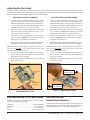
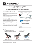
1
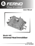
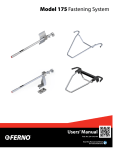
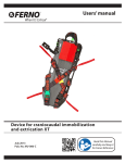
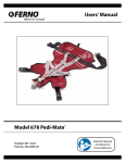
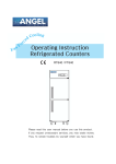
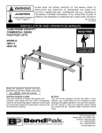
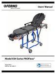
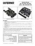
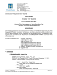
Accessory Kit 082-2134
Model 173 R
ear Hook Update
Rear
Description
This kit includes parts to update one Ferno® Model 173 cot
fastener. The update improves the function of the fastener by
adding precision adjustment.
Model 173
Rear Hook
The Model 173 cot fastener system and this kit are for use only
with Ferno® Model 28 and Model 28-Z PROFlexx® cots.
Updated fasteners remain compatible with all older Ferno®
Model 28 series cots.
Parts Supplied
1 ea ..................................................... Model 173 Rear Hook
Installation Instructions
234-3366-01
Before You Begin
Inspect your existing fastener hook before using this update kit.
•
If your fastener’s rear hook is permanently mounted to
the ambulance floor by two large screws, follow the
instructions in “Updating the Model 173-2 PermanentlyMounted Rear Hook” in this manual.
•
If your fastener’s rear hook attaches to an aluminum floor
plate, follow the instructions in “Updating the Model
173-3 Removable Rear Hook” in this manual.
•
Backing (or anchor) plates are required to be installed
under the ambulance at all mounting points. See the Model
173-2 or Model 173-3 Installation Manual for complete
installation details. Contact Ferno Customer Relations
for free manuals.
Ferno Customer Relations
Customer service and product support are important aspects
of each Ferno product. For assistance or information:
Telephone (Toll-free) .................................... 1.877.733.0911
Telephone .................................................... +1.937.382.1451
Fax (Toll-free) ............................................... 1.888.388.1349
Fax ............................................................... +1.937.382.6569
Internet ........................................................... www.ferno.com
Ferno-Washington, Inc.
70 Weil Way
Wilmington, Ohio 45177-9371 U.S.A.
© Ferno-Washington, Inc.
234-3366-01
October 2007
Parts Provided: Kit 082-2134
A fastener installed without backing plates
can fail in a crash. Use properly installed
backing plates to secure the fastener at all
mounting points.
Important
The fastener is designed to be installed with
backing (anchor) plates at all mounting points.
If the vehicle in which you are installing the fastener
does not have the required backing plates, have
them installed. See the Model 173-2 or 173-3
Installation Manual for complete installation
information.
Limited Warranty Statement
The products sold by Ferno are covered by a limited warranty.
The actual terms and conditions of the limited warranty, and
the limitations of liability and disclaimers, are available upon
request by calling 1.800.733.3766 or 1.937.382.1451.
1
Updating the Model 173-2
Permanently-Mounted Rear Hook
ITEMS REQUIRED FOR INSTALLATION
(NOT SUPPLIED)
Hook
1/2" Socket head cap screw* ........................................... 2 ea.
1/2" Jam nut* ................................................................... 2 ea.
1/2" Lock washer ............................................................. 2 ea.
* The socket head cap screws and jam nuts should be of at
least SAE Grade 5, with a corrosion-resistant coating (zinc
plating recommended) and a UNC-2 threading. The length of
the screws will be determined by the combined thickness of
the patient compartment floor and backing plates. When
installed, the screws should extend beyond the backing plates
a minimum of 3/4" (1.9 cm).
REAR
DOORS
TOOLS REQUIRED
1/4" Allen wrench ............................................................ 1 ea.
3/4" Box or socket wrench .............................................. 1 ea.
• Penetrating oil (WD-40®, Liquid Wrench® or similar)
Figure 1 - Mounting the Rear Hook
REMOVING THE OLD REAR HOOK
Important
Ferno specifies 1/2" socket head cap screws be used to mount
the Model 173-2 fastener. These screws can be removed using
a 1/4" Allen wrench and 3/4" box or socket wrench.
Do not reuse any portion of the old rear hook.
Discard the old rear hook and the screws, jam nuts
and washers from the previous installation. Use
only new screws, jam nuts and washers to install
the new rear hook.
If the screws are difficult to remove, apply a penetrating oil
(for example, WD-40®, Liquid Wrench® or similar) for the
contact time recommended by the manufacturer.
Do not reuse any old parts. Discard the old rear hook and the
screws, jam nuts and washers from the old installation. Use
only new screws, jam nuts and washers to install the new rear
hook.
Clean the area where the old rear hook was installed before
installing the new rear hook.
INSTALLING THE NEW REAR HOOK
1.
Place the rear hook on the ambulance floor with the hook
facing the antler (away from the rear doors as indicated
in Figure 1).
2.
Attach the rear hook with two new 1/2" socket head cap
screws, new lock washers, and new jam nuts. To ensure
proper thread engagement, the screws should be long
enough to extend beyond the backing plates a minimum
of 3/4" (1.9 cm).
WD-40® is a trademark of the WD-40 Company.
Liquid Wrench® is a trademark of Radiator Specialty Company.
2
© Ferno-Washington, Inc.
234-3366-01
October 2007
Updating the Model 173-3
Removable Rear Hook
ITEMS REQUIRED FOR INSTALLATION
(NOT SUPPLIED)
Hook
Jam Nut
1" Socket
Head Cap
Screw
1/2"-13 x 1" Socket head cap screw* ............................. 1 ea.
1/2"-13 x 1-1/4" Socket head cap screw* ....................... 1 ea.
1/2"-13 Jam nut* ............................................................. 1 ea.
* The socket head cap screws and jam nut should be of at least
SAE Grade 5, with a corrosion-resistant coating (zinc plating
recommended) and a UNC-2 threading.
TOOLS REQUIRED
1/4" Allen wrench ............................................................ 1 ea.
1/2" Min. Gap
1-1/4" Socket Head
Cap Screw
REAR
DOORS
REMOVING THE OLD REAR HOOK
Keyhole
To remove the old rear hook:
1.
2.
3.
Use a 1/4" Allen wrench to remove the socket-head cap
screw closest to the rear doors.
Slide the rear hook toward the rear doors to position the
upside-down socket head cap screw in the large end of
the keyhole slot in the floor plate.
Lift the rear hook straight up to remove it from the
mounting plate.
Do not reuse any old parts. Discard the old rear hook and the
screws and jam nut from the old installation. Use only new
screws and a new jam nut to install the new rear hook.
Figure 2 - Attaching the Rear Hook
Important
Do not reuse any portion of the old rear hook.
Discard the old rear hook and the screws and jam
nut from the previous installation. Use only new
screws and a new jam nut to install the new rear
hook.
Clean the area where the old rear hook was installed before
installing the new rear hook.
INSTALLING THE REAR HOOK
1.
Thread a new 1-1/4" socket head cap screw upward
through the hole closest to the hook, leaving a 1/2" gap
between the screw head and the hook plate (Figure 2).
Secure the screw with a new jam nut, using a 3/4" box or
socket wrench to tighten the nut.
2.
Position the rear hook over the rear-hook floor plate,
with the hook facing the antler (away from the rear doors
as shown in Figure 2). Set the rear hook with the screw
head in the large part of the keyhole.
3.
Push the rear hook forward to seat the head of the screw
in the small end of the keyhole. (If the rear hook cannot
be pushed forward, remove the hook and adjust the
position of the 1-1/4" screw slightly, then reinstall the
rear hook).
4.
Use a new 1" socket head cap screw and 1/4" Allen
wrench to secure the rear hook to the floor plate.
© Ferno-Washington, Inc.
234-3366-01
October 2007
3
Adjusting the Rear Hook
The new rear hook is adjustable. To adjust the rear hook, first place the cot in the fastener and verify that the head-end crosstube
is engaged in the fastener antler. Then engage the rear hook as closely as possible against the cot. Follow the appropriate instructions
below to adjust the hook forward or rearward on the ratchet bar shaft.
ADJUSTING THE HOOK FORWARD:
ADJUSTING THE HOOK REARWARD:
1.
Lower the hook momentarily and use a 3/32" Allen
wrench to loosen the set screw located on top of the
ratchet bar shaft (Figure 3). Do not remove the set screw
- loosen it only. Then raise and engage the hook. (If you
can't raise the hook, the set screw is too loose.)
1.
Lower the hook momentarily and use a 3/32" Allen
wrench to loosen the set screw located on top of the
ratchet bar shaft (Figure 3). Do not remove the set screw
- loosen it only. Then raise and engage the hook. (If you
can't raise the hook, the set screw is too loose.)
2.
Use a 5/32" Allen wrench to loosen the socket head
cap screw at the rear of the ratchet bar, Figure 3. (To
loosen: turn counter-clockwise).
2.
At the front of the ratchet bar shaft, use a 7/16" socket
or box wrench to loosen the hex-head cap screw and
shaft, Figure 4. (To loosen: turn counter-clockwise).
3.
At the front of the ratchet bar shaft, use a 7/16" socket
or box wrench to tighten the hex-head cap screw and
shaft, Figure 4. (To tighten: turn clockwise).
3.
At the rear of the ratchet bar shaft, use a 5/32" Allen
wrench to tighten the socket head cap screw, Figure 3.
(To tighten: turn clockwise).
4.
Repeat Steps 2 and 3 until the cot is held firmly in place
by the hook with no front-to-back slack or wiggling.
4.
Repeat Steps 2 and 3 until the cot is held firmly in place
by the hook with no front-to-back slack or wiggling.
Note: If the shaft cannot be adjusted any further forward, move
the hook itself forward by one locking ratchet position, then
adjust the shaft using this position.
Note: If the shaft cannot be adjusted any further rearward, move
the hook itself rearward by one locking ratchet position, then
adjust the shaft using this position.
5.
Use the 5/32" Allen wrench to tighten the socket head
cap screw at the rear of the ratchet bar. Verify that both
front and rear screws are tight.
5.
Use the 7/16" wrench to tighten the hex-head cap screw
at the front of the ratchet bar. Verify that both front and
rear screws are tight.
6.
Disengage the hook and tighten the set screw with the
3/32" Allen wrench.
6.
Disengage the hook and tighten the set screw with the
3/32" Allen wrench.
Tighten (Adjust
Hook Forward)
Set Screw
Ratchet Bar
Shaft
Socket Head
Cap Screw
Figure 3 - Adjusting the Set Screw and
Socket Head Cap Screw
Parts and Service: U.S.A. and Canada
EMSAR® is the only agent authorized by Ferno to manage,
service, and repair Ferno products.
Telephone ................................................... 1.800.73.EMSAR
Telephone ...................................................... 1.937.383.1052
Fax ................................................................. 1.937.383.1051
Internet ...................................................... www.EMSAR.com
4
Loosen (Adjust
Hook Rearward)
Ratchet Bar
Shaft
Figure 4 - Adjusting the Shaft
Parts and Service:
Outside North America
To order Ferno parts and for professional repairs, contact your
Ferno distributor. Your distributor is the only agent authorized
by Ferno to manage, service, and repair Ferno products.
© Ferno-Washington, Inc.
234-3366-01
October 2007