1
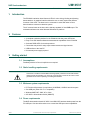
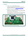
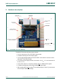
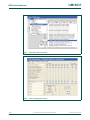
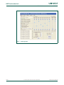
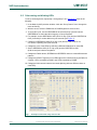
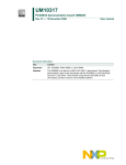
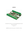
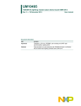
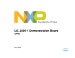
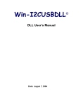
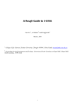
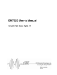
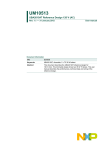
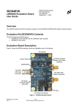
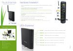
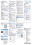
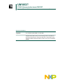
UM10537
PCA9634 demonstration board OM13327
Rev. 1 — 7 March 2012
User manual
Document information
Info
Content
Keywords
I2C, PCA9634, RGB, RGBA, 8 x 8-bit PWM
Abstract
The OM13327 is an add-on to the NXP I2C 2005-1 demo board. This
daughter board makes it easy to test and design with the PCA9634, an
8-bit Fast-mode Plus (Fm+) low power LED driver. These boards, along
with the I2CUSB Lite GUI (PC-based), provide an easy to use evaluation
platform.
UM10537
NXP Semiconductors
PCA9634 demonstration board OM13327
Revision history
Rev
Date
Description
v.1
20120307
user manual; initial release
Contact information
For more information, please visit: http://www.nxp.com
For sales office addresses, please send an email to: [email protected]
UM10537
User manual
All information provided in this document is subject to legal disclaimers.
Rev. 1 — 7 March 2012
© NXP B.V. 2012. All rights reserved.
2 of 13
UM10537
NXP Semiconductors
PCA9634 demonstration board OM13327
1. Introduction
The PCA9634 evaluation board features LEDs for color mixing, blinking and dimming
demonstrations. A graphical interface allows the user to easily explore the different
functions of the driver. The board can be connected in series with other I2C-bus
demo boards to create an evaluation system.
The IC communicates to the host via the industry standard I2C-bus/SMBus port. The
evaluation software runs under Microsoft Windows PC platform.
2. Features
•
•
•
•
•
•
A complete evaluation platform for the PCA9634 8-bit low power LED driver
Easy to use GUI based software demonstrates the capabilities of the PCA9634
On-board RGBA LEDs for visual experience
Convenient test points for easy scope measurements and signal access
USB interface to the host PC
No external power supply required
3. Getting started
3.1 Assumptions
Familiarity with the I2C-bus is helpful but not required.
3.2 Static handling requirements
CAUTION
This device is sensitive to ElectroStatic Discharge (ESD). Therefore care should be taken
during transport and handling. You must use a ground strap or touch the PC case or other
grounded source before unpacking or handling the hardware.
3.3 Minimum system requirements
•
•
•
•
PC Pentium 60 processor (or equivalent), 8 MB RAM, 10 MB of hard drive space
One USB port (either 2.0 or 1.1 compatible)
Windows 98SE, ME, 2000, XP, or Vista
I2C 2005-1 demonstration board (OM6275)
3.4 Power requirements
The NXP demonstration board I2C 2005-1 and OM13327 hardware obtain power from the
PC USB port. Care should be taken not to exceed the USB port current capabilities.
UM10537
User manual
All information provided in this document is subject to legal disclaimers.
Rev. 1 — 7 March 2012
© NXP B.V. 2012. All rights reserved.
3 of 13
UM10537
NXP Semiconductors
PCA9634 demonstration board OM13327
4. Installation
4.1 I2C 2005-1 board and WIN-I2CUSB Lite software
The OM13327 is a daughter card to the OM6275 I2C 2005-1 demo board. You may
download the WIN-I2CUSB Lite software, the OM6275 user manual UM10206, and find
ordering information at the NXP web site ics.nxp.com/support/boards/i2c20051/.
4.2 OM13327 connection to I2C 2005-1 board
The I2C 2005-1 demo board should be disconnected from your PC before mounting the
OM13327 board on to it. The OM13327 board has a 9-pin female connector that connects
to the JP1 male connector on the I2C 2005-1 board.
With both boards facing you, connect the OM13327 board to the I2C 2005-1 board before
connecting the USB cable. Once the board is connected, connect the USB cable and start
the WIN-I2CUSB Lite software. You are now ready to evaluate the PCA9634.
PCA9634 demo board
019aac698
Fig 1.
PCA9634 demo board (OM13327) mounting to the I2C 2005-1 demo board
UM10537
User manual
All information provided in this document is subject to legal disclaimers.
Rev. 1 — 7 March 2012
© NXP B.V. 2012. All rights reserved.
4 of 13
UM10537
NXP Semiconductors
PCA9634 demonstration board OM13327
5. Hardware description
RGBA LEDs
light diffuser
J1 select VDD
1-2 (5 V), 2-3 (3.3 V)
J3 9-pin extender
connector
J6 LED output
test points
PCA9634BS
J2 9-pin connector
to I2C 2005-1 board
J4/J5 internal 1.1 kΩ pull-up
jumpers for SDA/SCL
J7 OE test pin
SW1 for A[0:6] and OE
control setting
019aac699
Fig 2.
PCA9634BS demo board (OM13327)
The OM13327 board has following jumper headers:
• J2 is for connection to JP1 on I2C 2005-1 demo board.
• J6 allows monitoring all 8 LED output signals.
• J3 is for pass-through signals from the I2C 2005-1 demo board to connect in series
with other I2C-bus demo boards.
• J1 is used for power supply selection, connected 1-2 for VDD = 5 V and connected 2-3
for VDD = 3.3 V.
• J4 and J5 for internal 1.1 kΩ pull-up resistors option on SDA and SCL signals.
• J7 allows monitoring and control output enable (OE) input signal.
• SW1 8-position DIP switch to select I2C-bus address A[0:6] = SW1[1:7] for this device
and set output enable OE = SW1[8].
UM10537
User manual
All information provided in this document is subject to legal disclaimers.
Rev. 1 — 7 March 2012
© NXP B.V. 2012. All rights reserved.
5 of 13
xxxx xxxxxxxxxxxxxxxxxxxxxxxxxxxxxx x xxxxxxxxxxxxxx xxxxxxxxxx xxx xxxxxx xxxxxxxxxxxxxxxxxxxxxxx xxxxxxxxxxxxxxxxxxxxxx
xxxxx xxxxxx xx xxxxxxxxxxxxxxxxxxxxxxxxxxxxx xxxxxxxxxxxxxxxxxxxxxx xxxxxxxxxxx xxxxxxx xxxxxxxxxxxxxxxxxxx
xxxxxxxxxxxxxxxx xxxxxxxxxxxxxx xxxxxx xx xxxxxxxxxxxxxxxxxxxxxxxxxxxxxxxx xxxxxxxxxxxxxxxxxxxxxxxx xxxxxxx
xxxxxxxxxxxxxxxxxxxxxxxxxxxxxxxxxxxxxxxxxxxxxx xxxxxxxxxxx xxxxx x x
1
2
3
3.3 V 1-2 VDD/LED = 5 V
JUMPER 2-3 V /LED = 3.3 V
DD
J1
NXP Semiconductors
6. Schematic
UM10537
User manual
5V
LED[0:7] test pins
HEADER 1 × 8
U1
LED2
LED3
4
1
3
R10
1.2 kΩ
R9
1.2 kΩ
R8
1.2 kΩ
LTST-C170AKT
R7
150 Ω
10 kΩ
10 kΩ
10 kΩ
10 kΩ
10 kΩ
10 kΩ
10 kΩ
R12
R13
R14
R15
R16
R17
R18
A6
A5
/OE
LED7
LED6
10 kΩ
15
14
13
12
11
R11
2
1
JUMPER J5
LED5
LED4
OVSARGB3R8
2
R2
1.1 kΩ
R1
1.1 kΩ
1
A1
A0
VDD
SDA
SCL
LED2
LED3
VSS
LED4
LED5
A2
A6
A3 PCA9634BS A5
A4
/OE
LED0
LED7
LED1
LED6
6
7
8
9
10
LED0
LED1
LED2
LED3
LED4
LED5
LED6
LED7
1
2
3
4
5
3.3 V switched
SCL
GND
SDA
IO1
IO2
A0
A1
A2
A3
A4
A5
A6
/OE
J7
1
/OE test pin
SW1
SW DIP-8
HEADER 1
Fig 3.
PCA9634 daughter card
UM10537
6 of 13
© NXP B.V. 2012. All rights reserved.
019aac700
PCA9634 demonstration board OM13327
J6
A2
A3
A4
LED0
LED1
J3
1
2
3
4
5
6
7
8
9
CON9-male
20
19
18
17
16
A1
A0
2
C3
0.1 μF
LED4
LED3
JUMPER J4
3
CON9-female
C2
0.1 μF
SDA
SCL
OVSARGB3R8
2
1
4
R6
1.2 kΩ
R5
1.2 kΩ
R4
1.2 kΩ
LTST-C170AKT
R3
150 Ω
3.3 V switched
SCL
GND
SDA
IO1
IO2
LED2
LED1
1
2
3
4
5
6
7
8
Rev. 1 — 7 March 2012
All information provided in this document is subject to legal disclaimers.
1
2
3
4
5
6
7
8
9
C1
10 μF
3.3 V unswitched
5 V unswitched
J2
5 V switched
PCA9634 VDD
UM10537
NXP Semiconductors
PCA9634 demonstration board OM13327
7. OM13327 demonstration board main components
Table 1.
OM13269 demo board main components
Device
Description
Address
Location
PCA9634BS
8-bit Fm+ I2C-bus low power
LED driver
0xC4 for I2C 2005-1 interface
U1
8. PCA9634 evaluation steps
The PCA9634 functions are controlled by WIN-I2CUSB Lite GUI. Refer to the PCA9634
data sheet for additional information on the registers and functionality.
8.1 Color mixing and dimming LEDs
1. Connect the hardware as described in Section 4. The PCA9634 address is set to
0xC4 on SW1 as A[0:6] = SW1[1:7] = 0100011 (0 → ON, 1 → OFF).
2. Start the GUI software.
3. The main screen will appear.
4. From the ‘Device’ drop-down menus select ‘LED Blinkers and Dimmers’, and from the
subsequent drop-down menu select ‘PCA9634 8-bit LED driver with 8-bit PWM’ as in
Figure 4.
5. The device configuration screen will be displayed as in Figure 5.
6. Un-check the ‘Sleep Enabled (oscillator off)’ box to enable the device, check the
‘Auto Write’ box (lower right), and click the ‘Write All’ button.
7. Go to the LED Driver Outputs (LEDOUT) pull-down tabs and for LED0 to LED7 select
‘LEDn controlled by PWMn and GRPPWM’.
8. With the cursor, move the PWMn bars in PWM Registers to change the colors on the
OM13327 board.
PWM0 controls the blue LED2.
PWM1 controls the green LED2.
PWM2 controls the red LED2.
PWM3 controls the amber LED1.
PWM4 controls the blue LED4.
PWM5 controls the green LED4.
PWM6 controls the red LED4.
PWM7 controls the amber LED3.
9. Once you set a color with the PWM values, move the GRPPWM bar in Group
Registers and observe the dimming effect as in Figure 6.
UM10537
User manual
All information provided in this document is subject to legal disclaimers.
Rev. 1 — 7 March 2012
© NXP B.V. 2012. All rights reserved.
7 of 13
UM10537
NXP Semiconductors
PCA9634 demonstration board OM13327
019aac701
Fig 4.
Drop-down menu selections
019aac702
Fig 5.
UM10537
User manual
Device configuration screen
All information provided in this document is subject to legal disclaimers.
Rev. 1 — 7 March 2012
© NXP B.V. 2012. All rights reserved.
8 of 13
UM10537
NXP Semiconductors
PCA9634 demonstration board OM13327
019aac703
Fig 6.
UM10537
User manual
Dimming effect
All information provided in this document is subject to legal disclaimers.
Rev. 1 — 7 March 2012
© NXP B.V. 2012. All rights reserved.
9 of 13
UM10537
NXP Semiconductors
PCA9634 demonstration board OM13327
8.2 Color mixing and blinking LEDs
To set-up a blinking demo, repeat step 1 through step 7 as in Section 8.1, then do the
following:
1. In the Mode 2 (0x25) selection window, check the ‘Group Control’ box to change the
mode to blinking.
2. With the cursor, move the PWMn bars in PWM Registers to select a color.
3. To set a blink cycle, use the GRPPWM bar to select the duty cycle and use the
GRPFREQ bar to select the blink frequency in Group Registers.
4. For example, set the GRPPWM to 0xE7 (90.23 % duty cycle) and the GRPFREQ to
0x2F (2 second) for a short blink every two seconds (see Figure 7).
5. Change the GRPPWM to 0x80 (50 % duty cycle) and the LED will be on for
one second, repeating every two seconds.
6. Change the color of the LEDs by selecting a different PWM value for each LED.
7. Set the GRPPWM to 0x52 (32 % duty cycle) and the GRPFREQ to 0x01
(0.08 second) and observe the pattern.
8. Change the PWMn values, GRPPWM and GRPFREQ values to create different blink
patterns.
9. Change the LEDOUT register on one LED output to be controlled only by its PWM, for
example, ‘LED1 controlled by PWM1’ and ‘LED6 controlled by PWM6’.
10. Change the blink rate and observe the results (blinking with two different colors on
each LED).
019aac704
Fig 7.
UM10537
User manual
Example of short blink every two seconds
All information provided in this document is subject to legal disclaimers.
Rev. 1 — 7 March 2012
© NXP B.V. 2012. All rights reserved.
10 of 13
UM10537
NXP Semiconductors
PCA9634 demonstration board OM13327
9. Support
For support, please send an e-mail to: [email protected].
10. Abbreviations
Table 2.
Abbreviations
Acronym
Description
ESD
ElectroStatic Discharge
GUI
Graphical User Interface
I2C-bus
Inter-Integrated Circuit bus
IC
Integrated Circuit
LED
Light-Emitting Diode
PC
Personal Computer
PWM
Pulse Width Modulator
RAM
Random Access Memory
RGB
Red/Green/Blue
RGBA
Red/Green/Blue/Amber
SMBus
System Management Bus
USB
Universal Serial Bus
11. References
UM10537
User manual
[1]
PCA9634, 8-bit Fm+ I2C-bus LED driver — Product data sheet;
NXP Semiconductors; www.nxp.com/documents/data_sheet/PCA9634.pdf
[2]
UM10206, “I2C Demonstration Board 2005-1 Quick Start Guide” —
NXP Semiconductors; www.nxp.com/documents/user_manual/UM10206.pdf
All information provided in this document is subject to legal disclaimers.
Rev. 1 — 7 March 2012
© NXP B.V. 2012. All rights reserved.
11 of 13
UM10537
NXP Semiconductors
PCA9634 demonstration board OM13327
12. Legal information
12.1 Definitions
Draft — The document is a draft version only. The content is still under
internal review and subject to formal approval, which may result in
modifications or additions. NXP Semiconductors does not give any
representations or warranties as to the accuracy or completeness of
information included herein and shall have no liability for the consequences of
use of such information.
12.2 Disclaimers
Limited warranty and liability — Information in this document is believed to
be accurate and reliable. However, NXP Semiconductors does not give any
representations or warranties, expressed or implied, as to the accuracy or
completeness of such information and shall have no liability for the
consequences of use of such information. NXP Semiconductors takes no
responsibility for the content in this document if provided by an information
source outside of NXP Semiconductors.
In no event shall NXP Semiconductors be liable for any indirect, incidental,
punitive, special or consequential damages (including - without limitation - lost
profits, lost savings, business interruption, costs related to the removal or
replacement of any products or rework charges) whether or not such
damages are based on tort (including negligence), warranty, breach of
contract or any other legal theory.
Notwithstanding any damages that customer might incur for any reason
whatsoever, NXP Semiconductors’ aggregate and cumulative liability towards
customer for the products described herein shall be limited in accordance
with the Terms and conditions of commercial sale of NXP Semiconductors.
Right to make changes — NXP Semiconductors reserves the right to make
changes to information published in this document, including without
limitation specifications and product descriptions, at any time and without
notice. This document supersedes and replaces all information supplied prior
to the publication hereof.
Suitability for use — NXP Semiconductors products are not designed,
authorized or warranted to be suitable for use in life support, life-critical or
safety-critical systems or equipment, nor in applications where failure or
malfunction of an NXP Semiconductors product can reasonably be expected
to result in personal injury, death or severe property or environmental
damage. NXP Semiconductors and its suppliers accept no liability for
inclusion and/or use of NXP Semiconductors products in such equipment or
applications and therefore such inclusion and/or use is at the customer’s own
risk.
design. It is customer’s sole responsibility to determine whether the NXP
Semiconductors product is suitable and fit for the customer’s applications and
products planned, as well as for the planned application and use of
customer’s third party customer(s). Customers should provide appropriate
design and operating safeguards to minimize the risks associated with their
applications and products.
NXP Semiconductors does not accept any liability related to any default,
damage, costs or problem which is based on any weakness or default in the
customer’s applications or products, or the application or use by customer’s
third party customer(s). Customer is responsible for doing all necessary
testing for the customer’s applications and products using NXP
Semiconductors products in order to avoid a default of the applications and
the products or of the application or use by customer’s third party
customer(s). NXP does not accept any liability in this respect.
Export control — This document as well as the item(s) described herein
may be subject to export control regulations. Export might require a prior
authorization from competent authorities.
Evaluation products — This product is provided on an “as is” and “with all
faults” basis for evaluation purposes only. NXP Semiconductors, its affiliates
and their suppliers expressly disclaim all warranties, whether express, implied
or statutory, including but not limited to the implied warranties of
non-infringement, merchantability and fitness for a particular purpose. The
entire risk as to the quality, or arising out of the use or performance, of this
product remains with customer.
In no event shall NXP Semiconductors, its affiliates or their suppliers be liable
to customer for any special, indirect, consequential, punitive or incidental
damages (including without limitation damages for loss of business, business
interruption, loss of use, loss of data or information, and the like) arising out
the use of or inability to use the product, whether or not based on tort
(including negligence), strict liability, breach of contract, breach of warranty or
any other theory, even if advised of the possibility of such damages.
Notwithstanding any damages that customer might incur for any reason
whatsoever (including without limitation, all damages referenced above and
all direct or general damages), the entire liability of NXP Semiconductors, its
affiliates and their suppliers and customer’s exclusive remedy for all of the
foregoing shall be limited to actual damages incurred by customer based on
reasonable reliance up to the greater of the amount actually paid by customer
for the product or five dollars (US$5.00). The foregoing limitations, exclusions
and disclaimers shall apply to the maximum extent permitted by applicable
law, even if any remedy fails of its essential purpose.
Translations — A non-English (translated) version of a document is for
reference only. The English version shall prevail in case of any discrepancy
between the translated and English versions.
Applications — Applications that are described herein for any of these
products are for illustrative purposes only. NXP Semiconductors makes no
representation or warranty that such applications will be suitable for the
specified use without further testing or modification.
12.3 Trademarks
Customers are responsible for the design and operation of their applications
and products using NXP Semiconductors products, and NXP Semiconductors
accepts no liability for any assistance with applications or customer product
I2C-bus — logo is a trademark of NXP B.V.
UM10537
User manual
Notice: All referenced brands, product names, service names and trademarks
are the property of their respective owners.
All information provided in this document is subject to legal disclaimers.
Rev. 1 — 7 March 2012
© NXP B.V. 2012. All rights reserved.
12 of 13
UM10537
NXP Semiconductors
PCA9634 demonstration board OM13327
13. Contents
1
2
3
3.1
3.2
3.3
3.4
4
4.1
4.2
5
6
7
8
8.1
8.2
9
10
11
12
12.1
12.2
12.3
13
Introduction . . . . . . . . . . . . . . . . . . . . . . . . . . . . 3
Features . . . . . . . . . . . . . . . . . . . . . . . . . . . . . . . 3
Getting started . . . . . . . . . . . . . . . . . . . . . . . . . . 3
Assumptions . . . . . . . . . . . . . . . . . . . . . . . . . . . 3
Static handling requirements . . . . . . . . . . . . . . 3
Minimum system requirements. . . . . . . . . . . . . 3
Power requirements . . . . . . . . . . . . . . . . . . . . . 3
Installation . . . . . . . . . . . . . . . . . . . . . . . . . . . . . 4
I2C 2005-1 board and WIN-I2CUSB Lite
software . . . . . . . . . . . . . . . . . . . . . . . . . . . . . . 4
OM13327 connection to I2C 2005-1 board . . . 4
Hardware description . . . . . . . . . . . . . . . . . . . . 5
Schematic . . . . . . . . . . . . . . . . . . . . . . . . . . . . . . 6
OM13327 demonstration board main
components . . . . . . . . . . . . . . . . . . . . . . . . . . . . 7
PCA9634 evaluation steps . . . . . . . . . . . . . . . . 7
Color mixing and dimming LEDs . . . . . . . . . . . 7
Color mixing and blinking LEDs . . . . . . . . . . . 10
Support . . . . . . . . . . . . . . . . . . . . . . . . . . . . . . . 11
Abbreviations . . . . . . . . . . . . . . . . . . . . . . . . . . 11
References . . . . . . . . . . . . . . . . . . . . . . . . . . . . 11
Legal information. . . . . . . . . . . . . . . . . . . . . . . 12
Definitions . . . . . . . . . . . . . . . . . . . . . . . . . . . . 12
Disclaimers . . . . . . . . . . . . . . . . . . . . . . . . . . . 12
Trademarks. . . . . . . . . . . . . . . . . . . . . . . . . . . 12
Contents . . . . . . . . . . . . . . . . . . . . . . . . . . . . . . 13
Please be aware that important notices concerning this document and the product(s)
described herein, have been included in section ‘Legal information’.
© NXP B.V. 2012.
All rights reserved.
For more information, please visit: http://www.nxp.com
For sales office addresses, please send an email to: [email protected]
Date of release: 7 March 2012
Document identifier: UM10537