1
GE Power Controls
SOLID STATE
SOFT STARTER
ASTAT Plus
USER MANUAL
REMARKS :
1. Read this manual throughly before using the ASTAT Plus, and store in a safe place for
reference.
2. Make sure that this manual is delivered to the end user
3. CE Marking
When using ASTAT Plus in the EU, compliance with EMC is required.
ASTAT Plus range comply with the generic EN 50081-2 and EN 50082-2
2. The policy of GE Power controls is one of continuous improvement.
The right is reserved to alter the design on any structural details of the products at any
time without giving notice.
ASTAT Plus. Soft Starters
WARNINGS
1.
Disconnect power before installing or servicing.
2
Hazardous voltages are present in the motor circuit even when the starter is OFF. An
isolation contactor is recommended, configured to provide automatic isolation when the
motor is turned OFF.
3.
Unit may contain more than one live circuit. Disconnect both control and main circuits
before installing or servicing.
4.
Soft stop should not be used as an Emergency stop.
5.
Stopping mode must be set to meet applicable standards for operator safety.
6.
Separate motor overcurrent protection is required to be provided in accordance with the
Canadian Electrical Code, Part 1. ASTAT Plus provides separate motor protection.
CAUTIONS
1.
Semi-conductor fuses specified may not provide branch circuit protection. Refer to local
applicable electrical codes.
2.
Overload relay setting should be properly coordinated with motor.
3.
Slow speed running will affect the motor thermal characteristic due to reduced cooling.
Care must be taken when operating motor under these conditions.
4
DC braking - braking current may cause motor overheating. Select the lowest braking
current and time.
5.
DC braking must use additional (DC3) in the motor circuit. See wiring diagram page 6-1.
6.
Abnormal starting times in excess of 30 seconds, or closely repeated operations of
acceleration ramp/deceleration ramp, slow speed, or DC injection braking may cause
motor damage. Contact motor manufacturer for proper motor selection.
7.
If control power is lost between starts, the overload relay protection is reset to cold start
conditions.
ASTAT Plus. Soft Starters
PRECAUTIONS
1.
Debranchez l'alimentation en courant électrique avant de raccorder ou d'intervenir.
2.
Des tensions dangereuses sort présente dans le circuit moteur même si le soft starter
indique la position "arrêt". Un contacteur d'isolement assurant un isolement automatique
quand le moteur est arrête, est recommendé.
3.
L'appareil peut renfermer plus d'un circuit sous tension de'brancher les circuits principaux
et les circuits de controle avant de raccorder ou d'intervenir.
4.
Délestage "soft stop" ne devrait jamais être utilisé en lieu de délestage d'urgence.
5.
Procédés de délestage doivent être conforme aux normes de sécurité des utilisateurs.
AVERTISSEMENTS
1.
Les fusibles semi-conducteurs specifies ne protégent pas obligatoirement les circuits se
conformer aux codes locaux d'installations électriques.
2.
Le relais de courant de surcharge doit être proprement coordonné avec la marche du
moteur.
3.
La marche en sous-régime agira sur les caracteristiques thermiques à cause de la
réduction de refroidessement. Opérez le moteur avec précaution dans en ce cas.
4.
Ralentissement courant continu peut provoquer la surchauffe de moteur. Choisissez le
plus foible courant de décéleration et la durée de ralentissement la plus courte.
5.
Pour freinage courant continu, un contacteur (DC3) additional est nécessaire dans le
circuit moteur, voir le schéma de raccordement page 6-1.
6.
Les délais anormaux de mise en service d'une durée supérieure à 30 secondes, ainsi
que les montées/descentes en regime, les exploitations régime lent ou les freinages par
injection de courant continu répétés et rapportes sont suseptibles d'edommager le
moteur. Mettez-vous en rapport avec votre fabricant en ce qui concerne le choix du
moteur adéquat.
7.
En cas d'interruption de l'alimentation entre deux dèmarrages, la protection assurée par
démarrage à froid.
8.
Le moteur doit être muni d'une protection distincte contre les surintensites, et la
surchauffe conformement au code de l'electricite, premiere partie. ASTAT Plus le relais
de courant de surcharge doit être proprement coordonne avec la marche du moteur.
INDEX
Section 1. Generalities ...................................................................................................................
1-1
1-2
1-1
Comparison of starting systems .........................................................................................
Advantages of the ASTAT Plus Solid State Soft Starters ....................................................
1-1
1-2
Section 2. Types and Ratings .......................................................................................................
2-1
2-1
2-2
2-3
IEC ratings ........................................................................................................................
UL ratings ..........................................................................................................................
Thermal characteristics ......................................................................................................
2-1
2-2
2-2
Section 3. Technical specifications ...............................................................................................
3-1
3-1
3-2
3-3
3-4
General Specifications .......................................................................................................
I/O Terminal Board Specification .......................................................................................
I/O Wiring ..........................................................................................................................
Operating modes ...............................................................................................................
3-1
3-2
3-3
3-4
Section 4. Programming. ..............................................................................................................
4-1
4-1
4-2
4-3
4-4
4-5
4-6
Keypad and display description .........................................................................................
Parameter configuration ....................................................................................................
Monitor block parameters ...................................................................................................
Calibration block parameters .............................................................................................
Basic block parameters .....................................................................................................
Advanced block parameters ...............................................................................................
4-1
4-2
4-4
4-5
4-6
4-7
Section 5. Installation. ...................................................................................................................
5-1
5-1
5-2
5-3
5-4
5-5
Equipment installation ........................................................................................................
Fuses, contactors and supply wiring ..................................................................................
Start-up ..............................................................................................................................
Troubleshooting ..................................................................................................................
Thyristor Check .................................................................................................................
5-1
5-2
5-3
5-3
5-4
Section 6. Appendix. ......................................................................................................................
6-1
6-1
6-2
6-3
6.4
Application Diagrams ......................................................................................................... 6-1
Serial Communications ...................................................................................................... 6-4
Dimensions ........................................................................................................................ 6-12
PCB's Layout ..................................................................................................................... 6-13
ii
1. Generalities
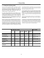
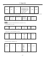
1-1. Comparison of starting systems
There are numerous applications where soft starting and limited
current peak are needed and thereby making direct starting of
squirrel-cage motors impossible. Traditionally in such cases other
types of starting with reduced stator voltage have been resorted to. The
best-known are star-delta starters, autotransformer starters, stator
resistance starters or using part winding motors.
Any reduced starting voltage imposes a current limitation, and as a
consequence the starting torque is also reduced, but there will always
be peaks during the change from one point or state to another which
can damage the machine being driven. In order to analyse the
performances offered by each of these different types of starters, the
following table shows the special characteristics of each of them,
comparing with the ASTAT system.
Note that in general all reduced voltage starts produce a reduction in
torque in squared proportion to the current in the phases of the motor
(not on the line) and the latter in turn is reduced in linear proportion to
the voltage. From this it can be deduced that any start with reduced
voltage reduces the torque in squared proportion to the voltage per
motor phase. From this point of view soft starting produces, just like any
other reduced voltage start, a reduction in starting torque, according
to the adjusted parameters. The advantage, of course, is the ease with
which this ramp can be controlled to produce a soft start in accordance
with the actual requirement of the machine.
From the comparison table it can be seen that the maximum starting
torque attainable using the soft system is 90% of that which direct
starting tends to. Bearing in mind that the direct starting torque varies
between 1.5 and 2.4 times rated torque, it can be deduced that with the
soft starter, starting torques which are somewhat higher than rated are
obtained.
This area includes the starting of pumps, fans, conveyor belts, etc.,
where a torque in the region of 60% of rated is usually sufficient for
correct starting.
As a general rule it can be guaranteed that soft starter will allow starting
of drives which are currently used in conventional starting systems,
with the advantages outlined, and above all the facility to adjust the
current peaks and torque at the machine, faced with the impossibility
or difficulty of varying the steps in conventional systems.
CONVENTIONAL STARTERS
SOFT STARTER
Direct
Autotransfo
Stator
resistance
Part
winding
motor
Star-delta
% of direct start
current (in the line)
100%
30 - 40 or 64%
58 - 70%
65%
33%
Depending on adjust,
max. 90%
% of direct start torque
100%
30 - 40 or 64%
33 - 49%
48%
33%
Depending on adjust,
max. 90%
Starting steps (1)
1
4, 3 or 2
3 or 2
2
2
Continuous, no steps
Connections to motor
3
3
3
6
6
3
Line overload
(approx.)
5 In
1,5 - 2,1 or 3,2 In
3 - 3,5 In
3,25 In
1,65 In
Depending on adjust,
max. 4-7 In
Change or
starting pause
NO
NO
NO
NO
YES
NO
(1) "Steps" mean sharp changes of speed during the time from rest until rated speed is reached.
1-1
1. Generalities
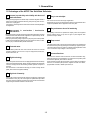
1-2. Advantages of the ASTAT Plus Solid State Soft starter
1 Increase in productivity and reliability with the use of
6 Easy to run and adjust
static soft starters.
Starting and stopping the motor without steps or transitions lengthens the life of
power-driven machine mechanical elements, greatly reducing stress on transmission and coupling parts.
Consequently, overhauling times are reduced and machine and facility lifespans
are lengthened.
This unit can be used for a wide range of applications.
Adjustments are very easy to make and diverse options may be selected to have
equipment capabilities suited to application needs every time.
7 Easy maintanence due to full monitoring
2 Improvement in acceleration / deceleration
characteristics
Being able to start by using the voltage ramp or alternatively by limiting current lets
acceleration fit the load characteristics. Application of a pulse start may also be
selected in cases of high static friction load.
Braking may be made by cutting-off power or by stop ramp, and it is also possible
to brake more energetically by feeding a DC current to the motor stator, so there
are many ways to obtain the best possible deceleration.
The signalling code based on alphanumeric display, makes the equipment
working conditions known at any time and gives a quick diagnosis when
protection security is violated.
8 Pump control
The ASTAT Plus includes a Pump Control function which is more effective than
the standard soft stop, reducing fluid surges or hammering in a pipe line system.
This method reduces the motor speed, by controlling internal parameters in the
motor as well as the output voltage in a close-loop system.
3 Protected motor
The soft starter protects the motor from overloads as well as from incorrect
operating conditions such as loss of an input or output phase, blocked rotor,
thyristor short circuit, etc.
4 Digital technology
The control system is based on the use of a highly specialized microcontroller by
which signals are treated digitally, thereby avoiding deratings and adjustments
common to analogue circuits and obtaining excellent precision and speed of
execution.
The control board is made with the technology of surface mounting devices
(SMD), which increases equipment reliability.
9 Advanced functions
The ASTAT Plus includes advanced functions, like linear acceleration ramp,
forward and reverse jog, programmable I/O or connection to a computer by serial
communication (RS 232), all included as standard.
These performances allows the incorporation of the soft starter to a distributed
control net, in automated plant processes, together with other soft starters,
programmable controllers, variable speed drives, etc.
5 High level of immunity
Design of the unit was closely tied to the conditions of supply lines, which handle
more disturbance every day. The control signals are optoelectronically isolated
and various levels of protection have been set up in the circuits to immunize the
equipment against external disturbance and its effects.
1-2
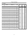
2. Types and ratings
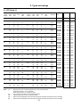
2-1. IEC Ratings (1)
HEAVY DUTY
Current
220V /
rating (2) 240V
380V /
415V
440V
480V /
500V
LIGHT DUTY
Current
220V /
rating (3) 240V
380V /
415V
440V
480V /
500V
Degree of
protection
A
kW(4)
kW(4)
kW(4)
kW(4)
A
kW(5)
kW(5)
kW(5)
kW(5)
14
3
3
5.5
5.5
7.5
7.5
7.5
17
4
4
7.5
7.5
7.5
7.5
11
IP-00
IP-00
17
4
4
7.5
7.5
7.5
7.5
11
21
5.5
5.5
11
11
11
11
13
22
5.5
5.5
11
11
11
11
15
27
7.5
7.5
13
13
15
15
32
7.5
7.5
15
15
18.5
18.5
22
38
10
10
18.5
18.5
48
13
13
22
22
22
22
30
58
15
15
63
15
15
30
30
37
37
37
75
72
20
20
37
37
37
37
45
105
30
30
55
55
55
55
156
40
40
75
75
240
63
63
315
TYPE
unit
Weight
Cooled
Kg.
Lbs.
QC1FDP
QC2FDP
4.3
4.3
9.48
9.48
Natural
Natural
IP-00
IP-00
QC1GDP
QC2GDP
4.3
4.3
9.48
9.48
Natural
Natural
15
IP-00
IP-00
QC1HDP
QC2HDP
4.6
4.6
10.14
10.14
Natural
Natural
22
22
25
IP-00
IP-00
QC1IDP
QC2IDP
4.6
4.6
10.14
10.14
Natural
Natural
25
25
30
30
37
IP-00
IP-00
QC1JDP
QC2JDP
12.5
12.5
27.56
27.56
By fan
By fan
22
22
37
37
45
45
45
IP-00
IP-00
QC1KDP
QC2KDP
12.5
12.5
27.56
27.56
By fan
By fan
86
25
25
45
45
50
50
50
IP-00
IP-00
QC1LDP
QC2LDP
17.0
17.0
37.48
37.48
By fan
By fan
75
126
37
37
63
63
75
75
80
IP-00
IP-00
QC1MDP
QC2MDP
17.0
17.0
37.48
37.48
By fan
By fan
90
90
110
187
55
55
90
90
110
110
132
IP-00
IP-00
QC1NDP
QC2NDP
45.0
45.0
99.20
99.20
By fan
By fan
110
110
132
132
160
288
80
80
150
150
165
165
200
IP-00
IP-00
QC1QDP
QC2QDP
45.0
45.0
99.20
99.20
By fan
By fan
90
90
160
160
200
200
220
378
110
110
200
200
220
220
250
IP-00
IP-00
QC1RDP
QC2RDP
55.0
55.0
121.3
121.3
By fan
By fan
370
110
110
200
200
220
220
250
444
132
132
220
220
250
250
315
IP-00
IP-00
QC1SDP
QC2SDP
55.0
55.0
121.3
121.3
By fan
By fan
475
150
150
250
250
250
250
335
570
160
160
300
300
355
355
400
IP-00
IP-00
QC1TDP
QC2TDP
80.0
80.0
176.4
176.4
By fan
By fan
610
200
200
315
315
400
400
400
732
220
220
400
400
450
450
500
IP-00
IP-00
QC1UDP
QC2UDP
105.0 231.5
105.0 231.5
By fan
By fan
850
250
250
450
450
530
530
600
1020
300
300
560
560
600
600
750
IP-00
IP-00
QC1VDP
QC2VDP
120.0 264.5
120.0 264.5
By fan
By fan
1075
355
355
600
600
670
670
750
1290
395
395
715
715
750
750
850
IP-00
IP-00
QC1XDP
QC2XDP
150.0 330.7
150.0 330.7
By fan
By fan
Notes:
(1)
=
(2)
(3)
(4)
(5)
=
=
=
=
Ratings in Amps. given for ambient temperature up to 40ªC and 1000m altitude
Derate output current by 1,5% / ºC above 40ºC.
Derate output current by 1% / 100m above 1000m
Heavy duty ratings, IEC Class 10 and 20 protections allowed
Light duty ratings, only IEC Class 10 protection allowed.
Maximum recommended Motor Power for IEC Class 20 protection. Set ASTAT's parameters "N" and "o" accordingly
Maximum recommended Motor Power for IEC Class 10 protection. Set ASTAT's parameters "N" and "o" accordingly
2-1
2. Types and ratings
2-2. UL Ratings
Current
rating
Max.
starting
current
HEAVY DUTY
200V
230V
460V
STANDARD DUTY
200V
230V
460V
Degree of
protection
A
A
HP
HP
HP
HP
HP
HP
14
70
3
-
3
-
7,5
3
-
3
-
7,5
IP-00
IP-00
17
85
3
-
3
-
10
3
-
3
-
10
22
110
5
-
7,5
-
15
5
-
7,5
-
34
170
7,5
-
7,5
-
20
10
-
48
240
10
-
15
-
30
63
315
15
-
20
-
72
360
20
-
105
525
156
TYPE
(1)
Weight
Cooled
Kg.
Lbs.
QC1FDP
QC2FDP
4.3
43
9.48
9.48
Natural
Natural
IP-00
IP-00
QC1GDP
QC2GDP
4.3
4.3
9.48
9.48
Natural
Natural
15
IP-00
IP-00
QC1HDP
QC2HDP
4.6
4.6
10.14
10.14
Natural
Natural
10
-
25
IP-00
IP-00
QC1IDP
QC2IDP
4.6
4.6
10.14
10.14
Natural
Natural
15
-
15
-
30
IP-00
IP-00
QC1JDP
QC2JDP
12.5
12.5
27.56
27.56
By fan
40
20
-
20
-
40
IP-00
IP-00
QC1KDP
QC2KDP
12.5
12.5
27.56
27.56
By fan
By fan
20
-
40
20
-
25
-
50
IP-00
IP-00
QC1LDP
QC2LDP
17.0
17.0
37.48
37.48
By fan
By fan
30
-
30
-
60
30
-
30
-
75
IP-00
IP-00
QC1MDP
QC2MDP
17.0
17.0
37.48
37.48
By fan
By fan
780
40
-
50
-
100
50
-
60
-
125
IP-00
IP-00
QC1NDP
QC2NDP
45.0
45.0
99.20
99.20
By fan
By fan
240
1200
60
-
75
-
150
75
-
75
-
200
IP-00
IP-00
QC1QDP
QC2QDP
45.0
45.0
99.20
99.20
By fan
By fan
315
1575
75
-
100
-
200
100
-
125
-
250
IP-00
IP-00
QC1RDP
QC2RDP
55.0
55.0
121.25
121.25
By fan
By fan
370
1850
100
-
125
-
250
125
-
150
-
300
IP-00
IP-00
QC1SDP
QC2SDP
55.0
55.0
121.25
121.25
By fan
By fan
500
2500
150
-
150
-
350
150
-
200
-
400
IP-00
IP-00
QC1TDP
QC2TDP
80.0
80.0
176.36
176.36
By fan
By fan
630
3150
200
-
200
-
400
200
-
250
-
500
IP-00
IP-00
QC1UDP
QC2UDP
105.0 231.47
105.0 231.47
By fan
By fan
850
4250
250
-
300
-
600
300
-
350
-
700
IP-00
IP-00
QC1VDP
QC2VDP
120.0 264.54
120.0 264.54
By fan
By fan
2-2
ASTAT-C / CD . Static soft starters
2. Types and ratings
2-3. ASTAT Plus, Thermal characteristics
The ASTAT Plus allows motor protection according IEC Class 10 or Class 20 and Nema 10, 20 or 30, free selectable by parameter "o" -overloadIEC Class 10
IEC Class 20
Sec.
Sec.
COLD
COLD
HOT
HOT
Ir / In
Ir / In
Nema 10
Nema 20
Sec.
Sec.
COLD
COLD
HOT
HOT
Ir / In
Ir / In
Nema 30
Thermal memory:
If the control voltage is not removed, the unit has a cool down characteristic, the time for cool down is 300 sec. after the overload trip.
If the control voltage is removed after tripping, you must wait, at least, 2
minutes before the unit can be restarted.
Sec.
Operations per hour:
Supposing a cycle T, with starting time of t1, running time of T-2t1 at
rated current and OFF time of t1 sec. at least, the ASTAT Plus allows
the following operations per hour.
COLD
HOT
Ir / In
2-3
Starting
Current
Operations / Hour.
Starting time t1= 10sec.
Operations / Hour
Starting time t1=20 sec.
2 Ir
3 Ir
4 Ir
180
160
30
90
60
10
3. Technical specifications
3-1. ASTAT Plus, General specifications
Voltage Ratings 3ph AC Systems
Freq. Range
50/60
Control
Specifications
Control system
Running
Up to 440V, +10%, -15% for QC1xDP ASTAT Plus series
Up to 500V, +10%, -15% for QC2xDP ASTAT Plus series
Hz
DC braking
Slow speed
Retry
Monitoring
Digital system with microcontroller
Starting ramp with progressive increase in voltage and current limitation
30 - 95 Un
10 - 90 Mdirect start
95 Un (90% Mdirect start), adjustable 0 to 999 ms
0,4 to 1,2 Ir (rated ASTAT current)
1 to 7 In
1 to 99 (types: standard or linear ramp up)
Output voltage reduction according to power factor
Fixed output voltage permanently equal to supply voltage
Direct control of a bypass contactor
1 to 120 (1 to 99 in secondary ramp) adjustable independently of starting ramp time (types: standard,
pump control or linear ramp down)
0 to 99 s. ; 0,5 to 2,5In
Direct torque: 7% or 14% of nominal speed; reverse torque: 20% of nominal speed
0 to 4 attemps, and 1 to 99 sec. retry time
Motor current, line voltage, power, power factor and elapsed time
External control
Acceleration phase
Permanent phase
Stop phase
Start - Stop
Adjustable time
Energy savings / Override choice
Power cut-off / Ramp / DC braking/Pump control
Initial voltage (pedestal)
Starting torque
Kick start
Motor current (Im)
Current limitation
Acceleration ramp time
Energy savings
Override
Bypass
Brake time by ramp
%
%
%
s
s
Inputs / Outputs Inputs
4 digital optocoupled. Two fixed (Start , Stop) , and 2 programmable (I3, I4)
1 Analog 0-5VDC for Tachogenerator input feedback
3 programmable relays, (1r, 2r, 3r)
1 Analog 0-10VDC output for current metering
Outputs
Protections
Control range of 45-65 Hz
Current limit
Overload
Cool-down time after
overload trip
Loss on input phase
Thyristor short circuit
Heatsink overheating
Motor thermistor
Loss on output phase
Stalled rotor
Supply frequency error
Overcurrent
Undercurrent
Overvoltage
Undervoltage
Error (CPU)
Memory
Long start time
Long slow speed time
Adjustable from 1 In to 7 In
IEC class 10 and 20 ; NEMA class 10,20 and 30 all selectable
s
s
ms
ms
ms
s
ms
Hz
ms
s
s
Environmental
conditions
Temperature
Relative humidity
Maximum altitude
Mounting position
Protection Degree
ºC
%
m
Standards
CE, cUL, UL
Conducted & Radiated emissions
Electrostatic discharges
Radioelectric interference
Immunity to fast trasients
Immunity to Surge Voltage
300 for reset
Trip at 3
Trip at 200
Trip at 200
Trip at 200 if thermistor impedance > response value
Trip at 3
Trip at 200
If f < 45 or f > 65, will not start
100 to 150% In; trip time adjustable from 0 to 99 sec.
0 to 99% In; trip time adjustable from 0 to 99 sec.
100 to 130% Un; trip time adjustable from 0 to 99 sec.
0 to 50% Un; trip time adjustable from 0 to 99 sec.
60
4 former errors
2 x ta (ta = acceleration ramp time)
120
0 to +55 (derate output current by 1,5% / ºC above 40ºC)
95% without condensation
3000 (derate output current by 1% / 100m above 1000m)
Vertical
IP00, UL Open
CE Conforming IEC 947-4-2; UL, cUL conforming to UL508
Conforming IEC 947 -4-2, Class A
Conforming to IEC 1000-4-2, level 3
Conforming to IEC 1000-4-6, level 3 and to IEC 1000-4-3, level 3
Conforming to IEC 1000-4-4, level 3
Conforming to IEC 1000-4-5, level 3
3-1
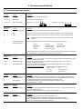
3. Technical specifications
3-2. I/O terminal board specifications
Power I/O terminals
Terminal
Function
1L1, 3L2, 5L3
Mains Input
Description
3ph input voltage according ASTAT Plus type.
2T1, 4T2, 6T3
Motor output
Output terminals to 3ph AC motor
A1, A2, B1, B2
Input Control Voltage
110/120V AC, +10%, -15%:
Digital Inputs
Terminal
57
Function
Common for digital inputs
Description
This is a common terminal for the digital input terminals specified below.
1
2
Run
Stop
Run order. Command signal may be provided by one NO dry momentary contact to terminals 1 and 57.
Stop order. Command signal may be provided by one NC dry momentary contact to terminals 2 and 57.
Note:
3
4
Programmable input I3
Programmable input I4
; 220/240V AC, +10%, -15%:
Run/Stop permanent command is allowed linking 1-57 and using one dry NO contact to 2-57
terminals.
These two inputs are programmable. Can be assigned to the following internal functions
-soft stop
-pump control
-kick start
-override
-DC brake
-slow speed control
-reverse slow speed
-local / remote control
-Linear Ramp
-dual ramp selection
-bypass function
Command signal should be provided by one NC dry contact to terminals 57-3 or terminals 57-4. By switching
this contact ON / OFF it is possible to enable or disable the assigned function.
Digital Outputs
Terminal
11, 12, 14
Function
Programmable relay1r
23, 24
Programmable relay 2r
33, 34
Programmable relay 3r
Analog I/O
Terminal
8
7
Function
Analog input common (-)
TG feedback input (+)
9
Current Output (+)
Motor thermistor terminals
Terminal
Function
5,6
Motor thermistor input
Communications
Terminal
Function
SG, TD, RD
Gr, Tx, Rx data
Description
11-12 = NC, 11-14 = N.O. dry contacts. This relay can be assigned to several internal output functions. (p. 3.6)
As default assigned to function RUN
23-24 = N.O. dry contact. This relay can be assigned to several internal output functions. (page 3-6)
As default assigned to function EOR
33-34 = N.O. dry contact. This relay can be assigned to several internal output functions. (page 3-6)
As default assigned to function DC BRAKE
Common for all relay output contacts
Maximum usage voltage: 380VAC (B300-UL)
Thermal current:
8A.
AC-15 use:
220V / 3A, 380V / 1A
DC-15 use:
30V max/ 3.5A
Description
This is a common terminal for the analog input terminal number 7, and analog output termnal number 9.
0-5V analog input for speed feedback. It should be provided by a DC tacho-generator coupled to the motor.
This speed feedback signal is required when the "linear ramp" function is used.
0-10V DC analog Output for current measurement purpose. Ir correspond to 2V DC
Load Impedance 10KΩ or higher
Description
This input allows a motor thermistor with a response value from 2,8 to 3,2KΩ , and a reset value from 0,75 to
1KΩ to control motor temperature.
When the motor thermistor is not used, a link must be used in terminals 5-6.
Description
RS232C, 3 wires, half duplex. Maximum cable length 3mts (10 feet)
Asynchronous data transmission, 9600 Bauds, 1 bit start, 8 bits data, 2 bits stop. no parity
ASCII and ModBus RTU protocols selectable from keypad as standard. (Check appendix 6-2)
Profibus DP and DeviceNet by external optional accessory
3-2
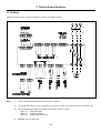
3. Technical specifications
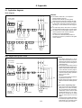
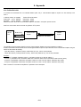
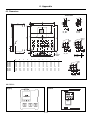
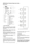
3-3. I/O Wiring
ASTAT Plus's terminal layout and wiring configuration is shown in the diagram of below
(1*)
(1*)
(3*)
(2*)
(4*)
(4*)
Notes:
(1*) Control and Mains wiring recommendations are given in chapter 5.
(2*) The programmable inputs I3, I4 are not assigned to any function as default. Check pages 3-6 prior to using these inputs.
(3*) The programmable
Relay (1r):
Relay (2r):
Relay (3r):
relay outputs are assigned to the following functions as default:
RUN, (RUN status)
EOR, (End of Ramp)
DCBR, (DC Braking control)
(4*) Important: Use dry contacts only
3-3
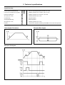
3. Technical specifications
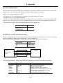
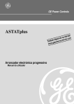
3-4. Operating modes
Starting and Stopping
Initial ramp
1
5 main frequncy cycles
Initial voltage (pedestal)
1a
30 to 95% Un (adjustable)
Kick start
2
95% Un. Enabled by parameter "Pxxx" to ON
Acceleration ramp (tramp)
3
Voltage ramp up from1 to 99s (adjustable). Dual ramp possibility
Linear speed ramp by tacho feedback also possible
3a
Fast increase of output voltage when motor gets rated speed
Current limit
4
1 to 7 In
Permanent state
5
Rated voltage (Override)
5a
Rated current
6
Energy savings. Enabled by "Fxxx" to OFF
7
Motor power cut-off. "Sxxx" to OFF, "Cxxx" to OFF
8
Deceleration ramp 1 to 120s (adjustable). Secondary ramp 1 to 99 s
Stopping modes
(All selectable)
Ramp dowm modes available are:
- Soft Stop -Voltage ramp down-. Enabled by "Sxxx" to ON
- Pump control. Selectable by "Sxxx" to ON and "Cxxx" to ON
- Linear ramp down (Tacho feedback needed)
Starting by voltage ramp
8a
Evolution of current in deceleration ramp mode
9
DC brake (0 to 99s adjustable). Enabled by "Bxxx" to ON
Starting by current limitation
Override
Override
Energy savings
Energy savings
3-4
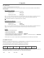
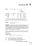
3. Technical specifications
Jog and linear ramp
Linear acceleration and deceleration ramp
1
1a
Ramp time adjustable (Selectable by parameter "Dxxx" to ON
Low slow (7%) and High slow (14%) speeds
2
3
Enabled by parameter "Jxxx" to ON and "jxxx" to LO or HI
Reverse slow speed (20%)
3a
Enabled by parameter "Jxxx" to ON and "rxxx" to ON
Slow speed (7% or 14%)
4
Enabled by parameter "Jxxx" to ON
Acceleration ramp
5
Ramp time adjustable
Soft stop (deceleration ramp)
6
Ramp time adjustable
Slow speed (7% or 14%)
7
Enabled by parameter "Jxxx" to ON
DC Brake
8
Current and time adjustables, Enabled by parameter Bxxx to ON, and bxx, Ixxx adjustments
Linear ramp with T.G. feedback
Slow speed. Basic diagram
Slow speed. Full diagram
3-5
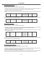
3. Technical specifications
Programmable Inputs and functions
The ASTAT Plus functions like Soft stop, kick start, and etc, can be enabled or disabled by setting ON or OFF in their dedicated parameters, using the facilities
provided by the keypad. Most of these functions can be enabled or disabled remotely as well, through the programmable inputs I3 or I4 (terminals board 3-57 and
4-57).
Function
Parameter
S
C
P
F
z
B
D
J
r
A
X
Soft Stop
Pump Control
Kick Start
Override
By-pass
DC Brake
Linear Ramp
(Jog). Slow Speed
Reverse Jog
Dual motor
Remote Control
x
x
x
x
x
x
x
x
x
x
x
x
x
x
x
x
x
x
x
x
x
x
Set Value
x
x
x
x
x
x
x
x
x
x
x
<Remarks>
_ O F F
The function is permanently disabled
_
O N
The function is permanently enabled
_
I
3
The status of the function depends on ASTAT's I3 input
_
I
4
The status of the function depends on ASTAT's I4 input
Note:
One programmable input may enable or
disable more than one function
More than one function can be enabled in the ASTAT Plus, either by the keypad or through the programmable inputs I3 and I4, but there are some functions
which may not work as expected during stopping, when are simultaneously enabled. The priority when two or more of the below functions are simultaneously
enabled is defined in the following table,
○
○
a
The Unit stops by Linear Ramp
○
○
○
○
c
○
○
b
The unit stops by DC brake after the Soft Stop is completed.
○
c
The unit stops by Pump Control
l
○
○
a
=O
=O
(S
Co
ntr
top
ft S
○
Pu
mp
So
○
○
c
○
○
○
○
N)
)
ON
)
S,
p(
○
l
D=
ON
B=
e(
am
ak
Br
rR
ea
DC
Lin
a
○
a
c
○
a
○
○
○
○
○
○
○
○
c
○
○
○
○
○
l
○
Pump Control (S, C=ON)
○
○
○
○
,C
b
○
b
○
N)
○
(S
○
○
○
○
Soft Stop (S=ON)
○
a
○
○
Linear Ramp (S, D=ON)
○
○
a
○
○
○
○
○
Action
ol
l
○
○
DC Brake (B=ON)
○
○
Condition
Programmable Relay Outputs
The ASTAT Plus includes three programmable relays 1r, 2r and 3r, (dry contacts). ASTAT terminals are 11-12-14, 23-24 and 33-34
These relays can be assigned to several functions, as shown bellow
Set Value
20
Relay N#
Parameter
Relay 1r
1 r x x
Relay 2r
1 r x x
Relay 3r
3 r x x
21
22
23
24
25
26
27
28
<Remarks>
EOR
DC Brake
Detects end of voltage ramp. -Only can be asigned to relay 2rDC Brake command -Only can be assigned to relay 3r-
Fault
Undervoltage
Detects ASTAT's fault status
Detects limit set in parameter UVxx
Overvoltage
RUN
Detects limit set in parameter OVxx
Detects ASTAT's run status
JOG
Undercurrent
Detects Jog (slow speed) status
Detects limit set in parameter UCxx
Overcurrent
Detects limit set in parameter OCxx
Disables the relay function
29
30
Future use
3-6
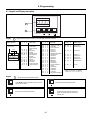
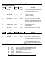
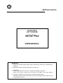
4. Programming
4-1. Keypad and Display description
1 2 3 4
1
0
1
2
C / V
Display
Displays Monitoring, Status indications, error messages and function set values
1
Display Structure
F V V V
O N
Function code
Data
F
V
Keypad
V
2
V
S
L
P
R
F
T
O
U
A
U
O
C
L
M
L
P
K
S
P
L
S
S
P
D
I
T
A
O
U
C
N
A
V
F
M
B
C
C
E
T
P
K
H
H
Status code
F V V V
Error code
F F/V V V
function code (*)
Equipment is connected
to main supply
(equipment is ON)
Stop
Remote stop
Kick start
Acceleration ramp
Full conduction or
Override
Energy saving
Soft stop
Pump control
DC braking
Inching / slow speed
Linear ramp (tacho)
E
E
E
E
E
E
E
E
E
E
E
E
E
E
E
E
E
E
E
E
E
Frequency out of range
Overload trip
Loss of synchronism
Phase U scr
Phase V scr
Phase W scr
Heatsink overtemperature
Motor thermistor
Phase U lost
Phase V lost
Phase W lost
Stalled rotor
Internal error
Long start time
Long slow speed time
Lock-out
Undervoltage
Overvoltage
Undercurrent
Overcurrent
Retry, attempts exceeded
M
v
.
.
P
.
.
L
T
a
d
S
.
.
L
.
.
Motor current
Software Version
.
.
Power Factor
.
.
Limit current
Starting Torque
Ramp up time
Ramp down time
Soft Stop selection
.
.
Lock out
.
.
0
0
0
0
0
0
0
0
0
0
0
0
0
0
0
0
0
0
0
0
0
1
1
1
1
1
1
1
1
1
2
2
2
2
2
2
2
2
2
3
3
3
0
1
3
4
5
6
7
8
9
0
1
2
3
5
6
7
8
9
0
1
2
x x x
x x x
F x x
x
x
x
x
x
x
x
x
x
x
x
x
x
x
x
K x x
(*) These are examples. Full details in
sections 4-2, 4-3, 4-4, 4-5 and 4-6
Allows setting of parameters and functions
SELECTION
SEARCH / ADJUSTMENT
Use with ↑ or ↓ to select the parameter or function code to be
displayed and/or modified
Decreases the value of the selected parameter
SEARCH / ADJUSTMENT
ENTER / SAVE
Increases the value of the selected parameter
- Introduces the new parameter value into memory
- Updates the selected parameter value with the
displayed value
C / V
4-1
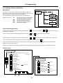
4. Programming
4-2. Parameter Blocks configuration
Mode Selection
The ASTAT Plus includes a large number of parameters which are divided in four
blocks: Monitor, Calibration, Basic and Advanced. The parameters of each group can be
displayed or skipped according the selection done in parameter "G".
The monitor parameters are always displayed regardless of the mode selected
Settings in parameter "G"
Gxxx
GCAL
GBAS
GADV
GALL
G ALL
Monitoring
Parameters
The Monitor parameters are always displayed,
whichever are the settings in parameter "G".
The Calibration parameters are displayed
The Basic parameters are displayed
The Advanced parameters are displayed
All parameters are displayed
G CAL
Calibration
Parameters
G BAS
Basic
Parameters
G ADV
Advanced
Parameters
Searching and Setting Parameters
The ASTAT Plus displays the parameters sequentially while depresing the
the parameter "G" is displayed.
There is a quick way to search automatically the parameter "G" by pressing
key and pushing repeteadly
C/V
C/V
Once the parameter "G" is displayed, choose the value desired by pressing
or
keys.Proceed in this way untill
and
Keys. "Gxxx" will be shown on the display.
or
Keys. The display will sequence "GBAS", "GCAL", "GADV" and
"GALL" values repeatedly. The actual value displayed can be stored in a temporal memory buffer by pressing
key.
Values stored in the temporal memory are lost upon control power loss, unless these are saved in the permanent E2PROM memory through parameter "W".
Additional indications are given in page 4-4
The above is an example given for parameter "G", but all ASTAT Plus parameters can be modified from its default factory value proceeding in similar way.
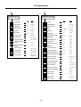
Parameter layout
Monitor parameters
Status
C/V
+
M
Shown automatically ON, STOP, LOCK, PULS, ...
(see page 4-4)
Motor Current
v
Software Version
V
Line Voltage
PF
Line Power Factor
w
Line Power
E
Elapsed time
e
Fault history Buffer
K
Password
W
E2PROM writting
G
Parameter Block Selector
GBAS
GADV
1
2
Calibration parameters
e0, e1, e2, e3
GALL
GCAL
4-2
U
Line Voltage
t
Voltage Calibration
100-500
UF
Unit frame
F,G ,H , ... ,X
m
Current Calibration
m
N
Motor rated current
40-120
o
Overload Protection
0, N1, N2, N3,C1,C2
f
Service Factor
100-130
4. Programming
1
2
Advanced Parameters
Basic Parameters
Unit
Range
minutes
00-45
Unit
L
Range
Current Limit
%
100-700
LK
Lock-out
T
Starting Torque
%
010-090
R
E2PROM Reading
ON, OFF
a
Ramp up time
sec.
01-99
Q
Factory Settings
ON, OFF
d
Ramp down time
sec.
01-120
Y
Retry
n. attempts
000-004
Retry time
sec.
001-099
p
Kick Start
mS.
000-999
y
b
DC Brake time
sec.
000-099
UV
Undervoltage
%
00-50
I
DC Brake current
%
050-250
uv
Undervoltage trip time
sec.
00-99
S
Soft Stop switch
OFF, ON, I3, I4
OV
Overvoltage
%
00-30
C
Pump Control switch
OFF, ON, I3, I4
ov
Overvoltage trip time
sec.
00-99
ST
Pump curve selection
starting
00-03
UC
Undercurrent
%
00-99
SP
Pump curve selection
stopping
uc
Undercurrent trip time
sec.
00-99
00-05
OC
Overcurrent
%
00-50
P
Kick Start Switch
OFF, ON, I3, I4
oc
Overcurrent trip time
sec.
00-99
F
Override Switch
OFF, ON, I3, I4
2a
Secondary Ramp up
sec.
01-99
z
By-pass Switch
OFF, ON, I3, I4
2d
Secondary Ramp down
sec.
01-99
B
DC Brake Switch
OFF, ON, I3, I4
PON, PI3, PI4
2t
Secondary Starting Torque
%
10-90
D
Tacho control switch
ON, OFF, I3, I4
J
Slow Speed switch
OFF, I3, I4
j
Low / High slow speeds
LO, HI
r
Reverse slow speed
OFF, ON, I3, I4
A
Dual motor switch
OFF, ON, I3, I4
X
Remote control switch
OFF, ON, I3, I4
XP
Comm Protocol selection
00-02
s
Station number
001-247
1r
Output relay 1r
22-30
2r
Output relay 2r
20, 22-30
3r
Output relay 3r
21, 22-30
4-3
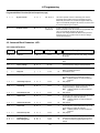
4. Programming
4-3. Monitor block Parameters
Display
O N
Function
Status
Default
O N
Range
Unit
ON
STOP
LOCK
PULS
RAMP
FULL
SAVE
SOFT
PUMP
DCBK
INCH
TACH
-
Switch on time. Equipment is connected to main supply
Stop
Remote control through serial port.
Kick start
Acceleration ramp
Full conduction / Override (full voltage)
Energy saving
Soft stop
Pump control
DC braking
Inching / slow speed
Linear ramp (tacho feedback needed)
000-999
1.0-9.9
A
kA
%
Displays motor current in Amps.
Current higher than 999A is displayed in kA
If parameter UFxx is not calibrated, the motor current is
displayed in %N
Description
M x x x
Motor Current
v x x x
Software Version
-
-
xxx = Version number
V x x x
Main Source Voltage
-
V
Displays line voltage in Volts.
P F x x
Power Factor
00-99
%
Displays line Power Factor
w x x x
Line Power
-
kW
Displays Line Power
E x x x
Elapsed time
-
Hrs
Displays RUN time in Hours (x 1000)
e x x x
Error trace buffer
e0xx-e3xx
-
Saves the last four errors
e0xx:
Fault 1 -Latest fault- xx: Fault code error
e1xx:
Fault 2
e2xx:
Fault 3
e3xx:
Fault 4
K x x x
Password
K 0 0 0
000-999
-
= 69
= 10
= 20
W x x x
E2PROM writting
W O F F
ON, OFF
-
Saves the unit current parameters to the E2PROM
This rewrites the last values saved
G x x x
Parameter display
selection
G B A S
CAL, BAS, ADV,
ALL
-
CAL:
BAS:
ADV:
ALL:
allows E2PROM writing operation
Key lock enabled
Key lock disabled
Displays Calibration Parameters
Displays Basic Parameters
Displays Advanced Parameters
Displays All parameters
Note: The Monitor block parameters are always
displayed
4-4
4. Programming
4-4. Calibration block Parameteres -CALDisplay
Function
Default
Range
Unit
Description
U x x x
Line Voltage setting
U 4 0 0
100-500
V
Line Voltage from 100 to 500V. Set rated value
t x x x
Voltage Calibration
t 4 0 0
000-600
V
Setting of this parameter allows better accuracy in monitoring or voltage protections. (Check the voltage calibration procedure)
U F
Unit Frame
U F
F, G, H, I, J, K, L,
M, N, Q, R, ...X
-
Unit frame rating (F,G,H,...X)
Setting 0 disables calibration
m x x x
Current Calibration
m 0 0 0
000-1000
A
Setting of this parameter allows better accuracy in monitoring or current protections. (Check the current calibration procedure)
N x x x
Motor Rated Current
N 1 0 0
040-120
%
100 x I motor/ I unit ratio
When this parameter is adjusted at a value higher than
105% the overload protection curve is automatically adjusted to Class 10. "C1", or to Nema 20 "N2"
o x x x
Overload Protection
o C 1
OFF
N1, N2, N3,
C1, C2
-
Selects either the following overload curves
OFF:
Overload protection disabled
(external overload relay must be used)
N1:
Nema 10
N2:
Nema 20
N3:
Nema 30
C1:
Class 10
C2:
Class 20
f x x x
Service Factor
f 1 0 0
100-130
%
Allows motor service factor. Applicable for Nema ratings
x
0
(*) Voltage calibration procedure
When the unit is installed on site or after PCB's replacement the voltage measurements may have accuracy of 10%. To improve the Voltage
measurement accuracy up to 3% proceed as follow.
1. Switch on the ASTAT and measure the RMS voltage on phases 1L1-3L2 using a calibrated voltmeter
2. Search the parameter "txxx", set the voltage measured and save this value by the
key. It is not necessary to rewrite the E2PROM
to make permanent the new setting, the ASTAT plus does this automatically.
NOTE: Set real voltage measured while ASTAT is Power ON. DO NOT enter motor nameplate rating
3. Once the ASTAT has been calibrated, this operation does not need to be repeated. Note however that the parameter "txxx" will show
the latest entry, which may differ from the actual voltage value.
(*) Current calibration procedure
When the unit is installed on site or after PCB's replacement the current measurements may have accuracy of 10%. To improve the Current
measurement accuracy up to 3% proceed as follow.
1. Search parameter "UF x" and enter the right ASTAT's frame type letter. ("F", "G", "H", ..etc.)
2. Start the motor, and measure the rms motor current using a calibrated Ammeter.
This measurement must be done after complete the starting, once the motor current has been stabilized.
3. Search the parameter "mxxx", set the current measured and save this value by the enter's keypad key. It is not necessary to rewrite the
E2PROM to make permanent the new setting, the ASTAT Plus do this automatically.
NOTE: Set real current measured while motor is running. DO NOT enter motor nameplate current rating
4. Once the ASTAT has been calibrated, this operation does not need to be repeated. Note however that the parameter "mxxx" will show
the latest entry, which may differ from the actual current value.
4-5
4. Programming
4-5. Basic block Parameteres. -BAS4-5-1. Basic Functions
Display
L x x x
Function
Current Limit
Default
Range
Unit
Description
L 3 5 0
100-700
%
Sets Device current limit. Sets motor current limit if parameter "N" is properly adjusted.
The maximum range setting is automatically calculated
by the unit according the following expression:
Max Limit = 450 / N (max allowed is 700%)
N is the motor capacity / unit capacity ratio adjusted in
parameter "Nxxx".
T
x x
Starting Torque
t
2 0
10-90
%
a
x x
Ramp Up time
a
2 0
01-99
sec.
Sets Voltage ramp up time. Motor acceleration time will
depend of load conditions.
d x x x
Ramp Down time
d 0 2 0
001-120
sec.
Sets Voltage ramp down time. Motor deceleration time
will depend of load conditions.
Enabled only if the parameter "Sxxx" is ON
p x x x
Kick start (1)
p 0 0 0
000-999
ms.
During the time adjusted, provides 95% of full voltage to
motor at starting time. Useful for high static-friction loads
Enabled only if the parameter "Pxxx" is ON
b
x x
DC Brake time (1)
b
0 0
00-99
sec.
I
x x x
DC Brake Current (1)
I
0 5 0
050-250
%
Provides DC braking at stopping time.
Enabled only if the parameter "Bxxx" is ON
Range
Sets the initial voltage applied to the motor
4-5-2. Programmable Basic Functions
Display
Function
Default
Description
S x x x
Soft Stop selector
S O F F
OFF, ON, I3, I4
Enables or disables all modes of Soft stop
C x x x
Pump Control selector
C O F F
OFF, ON, I3, I4
Enables the Pump control function. Usefull to limit fluid hammering.
The parameter "Sxxx" must also be enabled.
NOTE: Parameters "p ", "b " and "I " are disabled while "C" is ON
S T X X
Pump Curve selection
at starting phase
S T 0 0
00-03
Choice of various pump control algorithms for starting
00: Voltage ramp up
01-03: Various pump algorithms
S P X X
Pump Curve selection
S P 0 2
at stopping phase
Notes:
- Curve 00 (both ST00, SP00):
- Curve 01 (both ST01, SP01):
- Curve 02 (both ST02, SP02):
- Curve 03 (both ST03, SP03):
- Curve 04 (SP04):
- Curve 05 (SP05):
00-05
Choice of various pump control algorithms for stopping phase
00: Voltage ramp down
01-05: Various pump algorithms
Standard voltage ramp up -starting- and ramp down -soft stopPump Algorithm based on estimated average PF -power factor- , with large sampling period
Pump Algorithm based on instantaneous PF with short sampling period
Pump Algorithm based on estimated average PF with short sampling period
As Curve 3, but with high accuracy on PF average estimation
Pump Algorithm based on former ASTAT CD
P x x x
Kick Start selector
P O F F
OFF, ON, I3, I4
Enables or disables the KIck start function
If Pump control function C is enabled, both Kick start and DC Brake
functions are internally disabled
F x x x
Override selector
F O F F
OFF, ON, I3, I4
When this function is enabled, the unit provides constant full voltage
after starting, producing the lowest harmonic distortion. Note that the
energy saving function is disabled when Override is enabled.
4-6
4. Programming
Programmable Basic Functions (follow from previous page)
z x x x
By-pass selector
z O F F
OFF, ON, I3, I4
This function provides control of an external by-pass contactor,
significantly lowering heating losses and eliminating harmonics.
When the By-Pass function z is enabled, the programmable relay
output 2r is automatically assigned to this function, and must be used
to control the external by-pass contactor
B x x x
DC Brake selector
B O F F
OFF, ON, I3, I4,
PON, PI3, PI4
Enables or disables the DC brake function
When the DC Brake function B is enabled, the programmable relay
output 3r is automatically assigned to this function.
PON, PI3 or PI4 settings enable the DC Brake function just before
starting the motor. This is usefull to stop a fan which is rotating in
reverse at the starting time
4-6. Advanced Block Parameters -ADV4-6-1. Advanced Functions
Function
Display
Default
Range
Unit
Description
L K x x
Lock-Out
L K 0 0
00-45
min.
Sets time between consecutive starts. Setting "0" disables
this function.
R x x x
E2PROM reading
R O F F
ON, OFF
-
Loads the parameters from the E2PROM to the temporal
buffer
Q x x x
Factory settings
Q O F F
ON, OFF
-
Loads default factory settings to the temporal buffer.
Y
x
Retry
Y
0
0-4
-
y
x x
Retry time
y
1 0
01-99
sec.
Allows up to four tries of automatic restart after a fault.
Setting 0 disables this function.
Time between retries.
U V x x
Undervoltage
U V 0 0
00-50
%
u v x x
Undervoltage trip time
u v 2 0
00-99
sec.
O V x x
Overvoltage
O V 0 0
00-30
%
o v x x
Overvoltage trip time
o v 2 0
00-99
sec.
U C x x
Undercurrent
U C 0 0
00-99
%
u c x x
Undercurrent trip time
u c 2 0
00-99
sec.
O C x x
Overcurrent
O C 0 0
00-50
%
o c x x
Overcurrent trip time
o c 2 0
00-99
sec.
2 a x x
2 d x x
2 T x x
Dual Ramp Up
Dual Ramp Down
Dual StartingTorque
2 a 2 0
2 d 2 0
2 T 2 0
01-99
01-99
10-90
sec.
sec.
%
4-7
The unit trips if the line voltage decreases below the
percentage set. Setting 0 disables this protection.
Note: Calibrate parameter U before enabling this
protection.
Delay trip time
The unit trips if the line voltage increases above the percentage set. Setting 0 disables this protection.
Note: Calibrate parameter U before enabling this
protection.
Delay trip time
The unit trips if the current decreases below the percentage set. Setting 0 disables this protection.
Note: Calibrate parameter U before enabling this
protection.
Delay trip time
The unit trips if the current increases above the percentage set. Setting 0 disables this protection.
Note: Calibrate parameter U before enabling this
protection.
Delay trip time.
These are a secondary set of ramp up, ramp down and
starting torque parameters, which take over the primary
"a", "d" and "T" when the programmable function A is
enabled.
4. Programming
4-6-2. Programmable Advanced Functions
Display
Function
Default
Range
Description
This function provides linear acceleration and deceleration ramps in
a wider range of load conditions using tachogenerator feedback.
A DC Tacho-Generator coupled to motor must be used to provide an
analog signal feedback of 0-5VDC to terminals 7 and 8
D x x x
Linear Ramp
D O F F
OFF, ON, I3, I4
J
x x x
Slow Speed
J O F F
OFF, I3, I4
j
x x
Speed changeover
j
r x x x
Reverse
r O F F
OFF, ON, I3, I4
A x x x
Dual motor selector
A O F F
OFF, ON, I3, I4
This function allows dual motor control settings of acceleration,
deceleration and starting torque, and is useful to start or stop a motor
in diferent load conditions.
When this function is enabled, the parameters 2a, 2d and 2T take
over the parameters a, d and T. It allows dual motor control settings
X x x x
Remote control selector
X O F F
OFF, ON, I3, I4
X P x x
Comunication protocol
X P 0 0
00-02
Allows serial communication control by SG, TD and RD terminals.
Check Appendix section for more details
Sets serialcommunications protocol
0: ASCII 1: Modbus RTU
2: External modules (DeviceNet, ProfibusDP ...)
s x x x
Station number
s 0 0 1
001-247
L O
LO, HI
This function enables slow speed operation
Maximum operation time 120sec.
LO: Low Speed, 7% of rated speed.
HI: High Speed, 14% of rated speed.
Reverse direction is allowed in "High slow speed" mode only. It
provides 20% of rated speed
ASCII protocol allows a maximum of 90 stations only
4-6-3. Programmable Relay Output Functions
Display
Function
Default
Range
Description
1 r x x
Output relay 1r
1 r 2 5
(RUN)
22-30
2 r x x
Output relay 2r
2 r 2 0
(EOR)
20, 22-30
This is a programmable relay with one NO dry contact to ASTAT
Plus's terminals 23-24
This relay is automatically assigned to BY-Pass control if the function
z is ON. Any other assignment by the user is overwrited in this case
3 r x x
Output relay 3r
3 r 2 1
(DC Brake)
21, 22-30
This is a programmable relay with one NO dry contact to ASTAT
Plus's terminals 33-34
This relay is automatically assigned to DC-Brake control if the
function B is ON. Any other assignment by the user is overwrited in
this case
This is a programmable relay with one NO / NC dry contacts to
ASTAT Plus's terminals 11-12-14
The programmable relays can be set to the functions shown in the following table
Range
Function
Remarks
20
21
22
23
24
25
26
27
28
29
30
EOR
DC Brake
FAULT
Undervoltage
Overvoltage
RUN
Slow Speed
Undercurrent
Overcurrent
Disabled
Future use
Detects end of voltage ramp. -This function only can be assigned to relay 2rDC Brake control command -This function only can be assigned to relay 3rDetects unit Fault status. ON is normal status and switches OFF if a fault occurs
Detects Undervoltage according limit adjusted in function UV
Detects Overvoltage according limit adjusted in function OV
Detects unit RUN status
Detects slow speed status
Detects Undercurrent according limit adjusted in function UC
Detects Overcurrent limits as adjusted in function OC
Disables the relay function
4-8
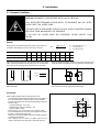
5. Installation
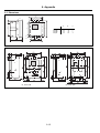
5-1. Equipment installation
CAUTION! DISCONNECT POWER BEFORE INSTALLING OR SERVICING
ONLY SPECIALIZED PERSONNEL SHOULD INSTALL THE EQUIPMENT AND ONLY AFTER
HAVING READ THIS USER'S GUIDE.
THE USER ITSELF IS RESPONSIBLE FOR ANY PHYSICAL INJURY OR MATERIAL DAMAGE
RESULTING FROM MISHANDLING THE EQUIPMENT.
IF YOU HAVE ANY DOUBTS ABOUT ANY PROCEDURE, PLEASE CONTACT YOUR
DEALER.
Remarks
Supply wire conductors should have the same section as direct starters. As
an indication, Vd voltage drop in wires should not be more than 2%.
R = conductor resistance (mΩ / m)
L = conductor length (m)
In = motor rated current (A)
3 x R x L x In
Vd =
1000
Conductor section (mm2)
2,5
4
6
10
16
25
35
50
100
150
Resistance R (Cu) 20ºC (mΩ / m)
7,5
4,55
3,05
1,85
1,13
0,725
0,528
0,254
0,183
0,122
1,86
1,188
0,868
0,416
0,3
0,2
Resistance R (Al) 20ºC (mΩ / m)
Signal wiring should be no longer than 3mts (up to 25mts.when using screened
cable), and should be separate from power wires (line, motor, command relays,
etc.) by at least 10cm, and if they cross, they should do so at a 90º angle
10 cm
Relays and contactors located in the same housing as the equipment should
have an RC suppressor parallel to the coil (or a reverse diode, if controled by DC).
8 cm
SIGNAL
POWER
CORRECT
A C
INCORRECT
Do not install capacitors to correct the power factor between equipment
output and motor
D C
If the equipment is fed by a line transformer, its rated power should be at least 1.5
times, but less than 10 times, higher than equipment supply.
Environment
When installing equipment, keep the following points in mind :
- The equipment should be installed vertically and hang over a platform or
bars. The vertical position is essential for proper cool air circulation
- Environmental conditions are in accordance with the following ranges and
maximum values :
- Operating temperature : 0ºC to +55ºC
- Relative humidity (without condensation) : 95%
- Maximum altitude : 3000m
Reduce rating by 1.5% / ºC from 40ºC and 1% / 100m from 1000m
- Do not install equipment in environments containing explosive or flammable gases, or near important heat sources
- Equipment should be well ventilated, with minimum keeping clearances
as indicated in the illustration.
- When equipment is to be mounted on a platform subject to strong
vibrations, there should be an elastic base to protect the equipment.
150mm
50mm
50mm
ASTAT
100mm
5-1
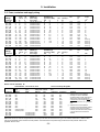
5. Installation
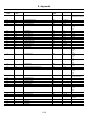
5-2. Fuses, contactors and supply wiring
Cat Number
A
Total
losses
100% In
W
QC _ F DP
QC _ G DP
QC _ H DP
QC _ I DP
QC _ J DP
QC _ K DP
QC _ L DP
QC _ M DP
QC _ N DP
QC _ Q DP
QC _ R DP
QC _ S DP
QC _ T DP
QC _ U DP
QC _ V DP
QC _ X DP
17
21
27
38
58
75
86
126
187
288
378
444
570
732
1020
1290
67
78
88
116
208
277
302
389
719
1097
1286
1374
2086
2352
3000
3839
25
32
40
63
80
100
125
200
250
400
500
630
800
1000
1250
2x800
6,600 CP URC 14.51/40
6,6 URD 30 XX 0063
6,6 URD 30 XX 0080
6,6 URD 30 XX 0100
6,6 URD 30 XX 0125
6,6 URD 30 XX 0160
6,6 URD 30 XX 0160
6,6 URD 30 XX 0250
6,6 URD 30 XX 0315
6,6 URD 31 XX 0500
6,6 URD 31 XX 0630
6,6 URD 32 XX 0800
6,6 URD 33 XX 1000
6,6 URD 33 XX 1250
6,6 URD 233 XX 2000
6,6 URD 233 XX 2000
00
00
00
00
00
00
00
00
00
2
2
2
3
3
-
In
Fuses
aM
(F1)
A
Fuses
FERRAZ type
(XX=according
mech. design)
Fuses
BUSSMANN type
(Typower Sicu 660V~)
Size
In
Control voltage
Fuse
A
Consumpt.
VA
20
25
32
63
80
80
100
160
200
315
400
500
630
800
1000
1250
6,600 CP URC 14.51/40
6,6 URD 30 XX 0063
6,6 URD 30 XX 0080
6,6 URD 30 XX 0100
6,6 URD 30 XX 0125
6,6 URD 30 XX 0160
6,6 URD 30 XX 0160
6,6 URD 30 XX 0250
6,6 URD 30 XX 0315
6,6 URD 31 XX 0500
6,6 URD 31 XX 0630
6,6 URD 32 XX 0800
6,6 URD 33 XX 1000
6,6 URD 33 XX 1250
6,6 URD 233 XX 2000
6,6 URD 233 XX 2000
00
00
00
00
00
00
00
00
00
2
2
2
3
3
-
1
1
1
1
2
2
2
2
2
2
4
4
4
4
4
4
18
18
18
18
55
55
55
55
78
78
118
118
118
248
248
248
IEC Class 10
Ratings
In
Cat Number
A
Total
losses
100% In
W
QC _ F DP
QC _ G DP
QC _ H DP
QC _ I DP
QC _ J DP
QC _ K DP
QC _ L DP
QC _ M DP
QC _ N DP
QC _ Q DP
QC _ R DP
QC _ S DP
QC _ T DP
QC _ U DP
QC _ V DP
QC _ X DP
14
17
22
32
48
63
72
105
156
240
315
370
475
610
850
1075
56
65
74
99
178
236
257
325
591
901
1063
1136
1721
1950
2491
3168
IEC Class 20
Ratings
Fuses
aM
(F1)
A
Fuses
FERRAZ type
(XX=according
mech. design)
Fuses
BUSSMANN type
(Typower Sicu 660V~)
Size
In
Control voltage
Fuse
A
Consumpt.
VA
1
1
1
1
2
2
2
2
2
2
4
4
4
4
4
4
18
18
18
18
55
55
55
55
78
78
118
118
118
248
248
248
(1) As per IEC 947
40
50
80
100
125
160
200
250
315
550
630
800
1000
1250
-
40
50
80
100
125
160
200
250
315
550
630
800
1000
1250
-
Contactor
DC 3
(2)
Conductor
section
2
mm
CL02
CL03
CL04
CL45
CL07
CL08
CL09
CK75
CK08
CK95
CK10
CK11
CK12
CK12
CK13
CK13
CL02
CL03
CL03
CL04
CL45
CL06
CL06
CL07
CL10
CK85
CK85
CK95
CK10
CK10
CK11
CK12
4
4
6
10
16
25
35
50
95
185
240
Bus bar (1)
Bus bar (1)
Bus bar (1)
Bus bar (1)
Bus bar (1)
Contactor
DC 1
Contactor
DC 3
(2)
Conductor
section
CL01
CL02
CL03
CL04
CL06
CL07
CL08
CL10
CK75
CK85
CK95
CK10
CK11
CK12
CK13
CK13
CL01
CL02
CL03
CL04
CL04
CL04
CL06
CL06
CL07
CK75
CK85
CK85
CK95
CK10
CK10
CK12
mm2
4
4
4
6
10
16
25
35
70
120
185
240
Bus bar (1)
Bus bar (1)
Bus bar (1)
Bus bar (1)
(2) The 3 contacts of DC3 must be connected in parallel
Branch Circuit Protection, UL
Gould-Shawmut, semi-conductor fuses
Short-Circuit Rating Max @480V
Type
Cat Number
A50QS 1
A50P2
Max. Fuse
Rating Class
RK5 & J
Max. Circuit
Breaker
Size
QC _ F DP
QC _ G DP
QC _ H DP
QC _ I DP
QC _ J DP
QC _ K DP
QC _ L DP
QC _ M DP
QC _ N DP
QC _ Q DP
QC _ R DP
QC _ S DP
QC _ T DP
QC _ U DP
QC _ V DP
50A
60A
80A
100A
150A
200A
225A
350A
450A
600A
2X500A in parallel
2x600A in parallel
-
2x1000A in parallel
2x1200A in parallel
2x1600A in parallel
30A
35A
40A
70A
100A
125A
150A
200A
350A
500A
600A
600A
-
35A
40A
50A
80A
125A
150A
150A
250A
350A
600A
700A
800A
800A
1000A
1200A
Type
Contactor
DC 1
NonCombination
Combination
25KA
25KA
25KA
25KA
25KA
25KA
25KA
25KA
65KA
65KA
65KA
65KA
65KA
65KA
65KA
5KA
5KA
5KA
5KA
10KA
10KA
10KA
10KA
25KA
25KA
25KA
25KA
*2
30KA
*2
30KA
65KA
<Remarks>
( ) Suitable for use on a circuit capable of
delivering not more than 100KA RMS
symetrical amperes, for 208V, 240V and up to
480V maximum, when used with the semiconductor fuse for short-circuit protection. Listed
with Gould Shawmut Form 101, Type A5QS or
A50P
1
( 2 ) Suitable for use on a circuit capable of
delivering not more than 65KA RMS symetrical
amperes, for 208V, 240V and up to 480V
maximum, when used with contactors (isolation
or by-pass) that are also rated for 65KA
withstand.
Note: When ASTAT Plus reduced voltage starters are used in conjunction with semi-conductor fuses, Typen 2 Co-ordination to IEC 947-4 is attained. These
fuses are recommended for best overall short-circuit protection. The semiconductor fuse specified may provide branch circuit protection. Refer to local
applicable electrical codes
5-2
5. Installation
5-3. Start-up
- Make sure equipment wiring corresponds to
one of the recommended routing diagrams or
equivalent
- If the motor has thermal protection sensor, remove the link between terminals
5 and 6 prior to wire the sensor
- Make sure the control wire harness corresponds to the control voltage used.
110/120V ac
A1 A2
- Adapt equipment rated current to motor, setting
the motor current In
Nxxx; xxx=
- Set overload trip curve as needed
oxxx ;
In (motor)
Ir (unit)
xx x
220/240V ac
B1 B2
A1 A2
Factory setting
x 100
N100
OFF = disabled (extermal overload relay must be used
C1/C2 =
IEC Class 10 or Class 20
N1/N2/N3= Nema 10, 20 or 30
- Set starting parameters as needed :
Lxxx =
Im (start)
In (motor)
B1 B2
Factory setting
o C1
Factory setting
x 100
Starting torque
Acceleration ramp time
Kickstart
Kickstart time
Current limit
T_xx
axxx
P ON/OFF/I3/I4
p x x x (if P enabled)
Lxxx
Factory setting
- Set braking parameters as needed :
Soft stop
Decceleration ramp time
DC injection brake
DC braking time
DC braking current
If you change the default configuration and wish
to keep it, remember to rewrite the parameters
in E2PROM as follows :
T _ 20
a_20
P OFF
P100
L300
S ON/OFF/I3/I4
dxxx
B ON/OFF/I3/I4
b _ x x (if B enabled)
I x x x (if B enabled)
- Set parameter K to ON (ON = 69 +
S OFF
d_20
B OFF
b__5
I 50
)
- Set parameter W to ON
- Press
(parameter W is set to OFF automatically)
- Send run command to equipment and make sure that operation is correct.
5-4. Troubleshooting
Symptom or Error
Possible Cause
Measures to be taken
No control voltage
Check wire harness and control voltage
F1 fuse blown on power supply PCB
Check and change, page 6-8
Bad connection of flat wire joining power
supply PCB to control PCB
Verify connectors
Equipment does not respond to
STOP / START controls
F2 fuse blown on power supply PCB
Check and change, page 6-8
Frequency error
(admits 45Hz ≤ f main ≤ 65Hz)
No 1L1 phase or frequence is out of range
Check 1L1 phase and/or mains frequence
Overload trip
Excesive load or excesive current during starting
Verify overload conditions during starting time and steady
state.
Check settings in parameters "Nxxx", "Lxxx", and "oxxx"
Display OFF
5-3
5. Installation
Symptom or Error & Error Code
Possible Cause
Measures to be taken
Synchronism loss
(Ex13)
Phase 1L1 lost
Check 1L1 phase
Phase U, V, W thyristor
(Ex14)
(Ex15)
(Ex16)
Shortcircuited thyristor
Check thyristor module
No output phases
Check 2T1, 4T2 and 6T3 phases
Heatsink thermostat
(Ex17)
Heatsink thermostat tripped by overheating or
defective
Check thermostat and wiring
Motor thermistor
(Ex18)
Motor thermistor tripped by overheating or defective Check thermistor and wiring
Phase U, V, W loss
(Ex19)
(Ex20)
(Ex21)
No input / output phases
Check power wire harness for 1L1, 3L2, 5L3,
2T1, 4T2 and 6T3
Defective thyristor or bad wire harness
Verify gate and cathode wire
harness. Verify thyristors
Stalled rotor
(Ex22)
Equipment detected stalled motor rotor
Restart equipment and check for an appreciable loss in
motor speed at any time (i.e. when the motor is loaded.
In this case, try jumping the bypass terminals 3-57 at the
end of acceleration ramp).
Internal error
(Ex23)
Microcontroller malfunction
Check IC1 and IC8 are correctly inserted in
their sockets
Long start time
(Ex25)
Current limit condition present more than
2 x ta sec. or 240 sec.
(ta = acceleration ramp time)
Increase current limit and / or acceleration
ramp time
Long slow speed time
(Ex26)
Equipment has been in slow speed mode more
than 120 sec.
Avoid this condition
Lock-out
(Ex27)
The time between startings is less that the
adjusted in parameter "LKxx"
Check is settings are correct
This protection may be disabled
Undervoltage
Overvoltage
(Ex28)
(Ex29)
The line voltage exceeds of limit set in
parameters "UVxx" or "OVxx"
Check is settings are correct.
This protection may be disabled
Undercurrent
Overcurrent
(Ex30)
(Ex31)
The motor current exceeds of limit set in
parameters "UCxx" or "OCxx"
Check is settings are correct.
This protection may be disabled
Retry
(Ex32)
The retry feature could not re-start the motor
after a fault
Check last message "e1xx" and correct.
Be sure that retry settings are correct as well.
5-5. Thyristor check
1L1 (3L2 or 5L3)
Shortcircuit
Use a testing lamp to check the defective power module between input and output phases.
If the lamp goes on, at least one of the thyristors has a shorcircuit.
Check with a tester the value or the R resistance between input and output of the same phase (connector
B on main PCB must be previously removed)
If R < 50KΩ, at least one of the thyristor is defective
Testing
lamp
3 to 6V
2T1 (4T2 or 6T3)
Open thyristor
L
S
With the simple assembly shown, the lamp should light when the S switch is closed and remain lite when
open.
If not, the thyristor is defective.
5-4
10 ohms
3 to 6V
6. Appendix
6-1. Application diagrams
Basic diagram
L1
L2
L3
Control Voltage
110 / 120V AC
Control Voltage
DC1 (1)
A1 A2
B1 B2
DC1
Control Voltage
220 / 240V AC
23 24
12 11 14
A1 A2
33 34
SG TD R D
1 L1 3 L2
5 L3
2 T1 4 T2
6 T3
B1 B2
1r
2r
3r
P ro gram m ab le re la y O utp uts
P ro gram m ab le In pu ts
I3
I4
1 57
2 57
3
57
REMARKS:
(1) The isolation contactor DC1, is not required to
perform operation to the motor.
Be aware however that DC1 provides galvanic
isolation from the incoming line increasing the safety.
(2) In this example, Start and Stop command is enabled
by push-buttons. Permanent command is allowed as
well, wiring 1, 2 and 57 terminals as shown in page 33.
(3) The output relays allow for direct action on contactors
according ratings specified in page 3-2 of this manual.
(4) The ASTAT Plus is provided with an electronic motor
overload protection, which should be adequate
protection for most of the applications.
You should use an external overload protection if
required by local codes or to protect the motor against
current unbalance.
(3)
5 6
4
7 8 9
FT1
FT1 (4)
Start
Stop
M
3~
Motor Thermistor
Push Button (2)
Basic diagram with By-Pass control
L1
L2
L3
Control Voltage
110 / 120V AC
Control Voltage
DC1 (1)
A1 A2
B1 B2
Control Voltage
220 / 240V AC
DC1
12 11 14
A1 A2
DC2
23 24
33 34
S G TD R D
1 L1
3 L2 5 L3
B1 B2
DC2
1r
2r
3r
P ro gram m ab le relay O u tp uts
P ro gram m ab le In pu ts
I3
I4
1 57
2 57
3
57
4
(3)
5 6
7 8 9
2 T1
4 T2
6 T3
FT1
FT1 (4)
Start /Stop
Permanent
Command (2)
Motor Thermistor
REMARKS:
(1) The isolation contactor DC1, is not required to perform operation to the motor.
Be aware however that DC1 provides galvanic isolation from the incoming line increasing the safety.
(2) In this example, Start and Stop command
is enabled by permanent command. Pushbuttons control is allowed as well, wiring 1,
2 and 57 terminals as shown in page 3-3.
(3) The output relays allow for direct action on
contactors according ratings specified in
page 3-2 of this manual.
(4) CAUTION:
In by-pass mode an external overload relay protection must be used.
(5) By-pass control using function "zxxx" and
external contactor DC2. Details given bellow.
M
3~
6-1
By-pass control. Programming steps
1. The by-pass function may be enabled by
setting "zxxx" to ON. In this case the bypass is automatically done after starting.
An alternative, if "zxxx" is set to one of the
programmable inputs "I3" or "I4", the bypass may be controlled by one remote
signal (5). Check section 4-5-2 for more
details.
2. Once this function is enabled, the relay 2r
is automatically assigned to this function
(check section 4-6-3). This relay must be
used to control the by-pass contactor.
6. Appendix
6-1. Application diagrams
Basic diagram with jog (slow speed) function
L1
L2
L3
Control Voltage
110 / 120V AC
Control Voltage
DC1 (1)
A1 A2
B1 B2
DC1
Control Voltage
220 / 240V AC
23 24
12 11 14
A1 A2
33 34
S G TD R D
1 L1 3 L2
5 L3
2 T1 4 T2
6 T3
B1 B2
1r
2r
3r
Pro gram m ab le re la y O u tp uts
Pro gram m ab le In pu ts
I3
I4
1 57
2 57
57
3
(3)
5 6
4
7 8 9
FT1
FT1 (4)
Start
Stop
Jog
Fw/ Rv
M
3~
Motor Thermistor
Slow Speed (5)
Push Button (2)
REMARKS:
(1) The isolation contactor DC1, is not required to perform
operation to the motor.
Be aware however that DC1 provides galvanic isolation
from the incoming line increasing the safety.
(2) In this example, Start and Stop command is enabled by
push-buttons. Permanent command is allowed as well,
wiring 1, 2 and 57 terminals as shown in page 3-3.
(3) The output relays allow for direct action on contactors
according ratings specified in page 3-2 of this manual.
(4) The ASTAT Plus is provided with an electronic motor
overload protection, which should be adequate protection for most of the applications.
You should use an external overload protection if
required by local codes or to protect the motor against
current unbalance.
(5) Slow Speed for Jog forward or reverse using programmable inputs I3, I4. Details given bellow.
Jog (Slow Speed) function. Programming steps
1. The slow speed function may be enabled by setting "Jxxx"
to I3. In this case Slow Speed is allowed by a push-button
wired to ASTAT's Plus terminals 3-57.
Reverse jog is also possible by setting "rxxx" to ON. As
alternative, if "rxxx" is set to programmable input I4,
forward or reverse may be controlled by remote pushbutton signal (5). Check section 4-6-3 for more details.
2. Slow Speed can be effected with ASTAT Plus in stop
status. Slow speed and normal run commands are internally interlocked.
Basic diagram with DC brake injection
L1
L2
L3
Control Voltage
110 / 120V AC
Control Voltage
DC1 (1)
A1 A2
B1 B2
Control Voltage
220 / 240V AC
12 11 14
A1 A2
DC3
DC1
23 24
33 34
S G TD R D
1 L1 3 L2
5 L3
2 T1 4 T2
6 T3
B1 B2
1r
2r
3r
P ro gram m ab le re la y O u tp uts
P ro gram m ab le In pu ts
I3
I4
1 57
2 57
3
57
4
(3)
5 6
7 8 9
FT1
DC3 (5)
FT1 (4)
Start /Stop
Permanent
Command (2)
Motor Thermistor
M
3~
6-2
REMARKS:
(1) The isolation contactor DC1, is not required to perform
operation to the motor.
Be aware however that DC1 provides galvanic isolation
from the incoming line increasing the safety.
(2) In this example, Start and Stop command is enabled by
permanent command. Push-buttons control is allowed
as well, wiring 1, 2 and 57 terminals as shown in page 33.
(3) The output relays allow for direct action on contactors
according ratings specified in page 3-2 of this manual.
(4) The ASTAT Plus is provided with an electronic motor
overload protection, which should be adequate protection for most of the applications.
You should use an external overload protection if
required by local codes or to protect the motor against
current unbalance.
(5) DC brake at stopping time is provided by the DC brake
function and external contactor DC3.
CAUTION:
The 3 contacts of DC3 must be connected in parallel.
Mandatory between 2T1 and 4T2 phases, otherwise a
short-circuit can occur
DC brake function. Programming steps
1. The DC function may be enabled by setting "Bxxx" to ON.
2. Once this function is enabled, the relay 3r is automatically
assigned to this function. This relay must be used to
control the DC brake contactor.
Check section 4-5-1 and 4-5-2 for more details
6. Appendix
6-1. Application diagrams
Basic diagram with Linear ramp
L1
L2
L3
Control Voltage
110 / 120V AC
Control Voltage
DC1 (1)
A1 A2
B1 B2
Control Voltage
220 / 240V AC
12 11 14
A1 A2
23 24
33 34
S G TD R D
1 L1 3 L2
5 L3
2 T1 4 T2
6 T3
B1 B2
1r
2r
3r
Pro gram m ab le re la y O u tp uts
Pro gram m ab le In pu ts
I3
I4
1 57
2 57
FT1
3
57
4
(3)
5 6
7 8 9
+
-
FT1 (4)
TAV-5
Start
Stop
Push Button (2)
Motor Thermistor
TG
M
3~
Linear Ramp (5)
6-3
REMARKS:
(1) The isolation contactor DC1, is not required to perform
operation to the motor.
Be aware however that DC1 provides galvanic isolation
from the incoming line increasing the safety.
(2) In this example, Start and Stop command is provided by
push-buttons. Permanent command is allowed as well,
wiring 1, 2 and 57 terminals as shown in page 3-3.
(3) The output relays allow for direct action on contactors
according ratings specified in page 3-2 of this manual.
(4) The ASTAT Plus is provided with an electronic motor
overload protection, which should be adequate protection for most of the applications.
You should use an external overload protection if
required by local codes or to protect the motor against
current unbalance.
(5) Linear ramp provided by "Dxxx" function. A tacho generator must be used as feedback. Details given bellow.
Linear ramp function. Programming steps
1. The linear ramp function may be enabled by setting
"Dxxx" to ON. In this case, linear ramp is independent of
the load.
This function needs the speed feedback provided by an
external tacho generator. Check section 4-6-2 for more
details.
6. Appendix
6-2. Serial Communication
Astat Plus is able to send and receive data through a serial RS232 port. Within this port Astat Plus communicates with a host (which can be
either with a PC / PLC or an industrial fieldbus system) to be started, stopped, programmed or checked.
3 different communication possibilities are available:
- Connection to a PC / PLC using ASCII protocol. (PC Windows communication software tool available)
- Connection to a PC / PLC using Modbus RTU protocol.
- Connection to industrial fieldbus systems (Profibus DP / DeviceNet). In this case it is necessary to use an external communications
module. Astat Plus communicates with this module using Modbus RTU protocol, and the module acts as a gateway to the fieldbus system.
In order to select the desired procedure the user must change the value of the parameter XP.
Protocol
ASCII
Modbus RTU
Profibus/DeviceNet
XP setting
0
1
2
6-2-1. RS232 port, wiring and communications settings
RS232 is an operating standard of communication only in terms of electrical characteristics (voltage, timing, etc.) while the communication
procedures are defined by different protocols (Modbus, ASCII, Profibus, DeviceNet, etc.).
The maximum allowed RS232 cable length is 3 meters. Astat Plus uses a connector with only 3 pins: TD, RD, SG.
Astat Terminal
TD
RD
SG
Name
Transmit Data
Receive Data
Signal Common
Pin
Computer
2
TD
RS232 connector
3
RD
D-SUB9
5
SG
ASTAT Plus
RS232 cable
The following table indicates the communications setting used by Astat Plus to perform data communication via its serial port
Name
Setting
Description
Baud Rate
Parity
Data Bits
Start Bits
Stop Bits
Data
Handshaking
9600 bps
None
8
1
2
ASCII / RTU
None
Bits per second transmission rate
Data error checking method
Number of data bits in each transmission
Number of bits to indicate beginning of transmission
Number of bits to indicate ending of transmission
Communications protocol used
No need to request to send or clear to send
6-4
6. Appendix
6-2-2. ASCII Protocol
To select this communications protocol, XP must be set to 0.
It is possible to operate the Astat Plus from a host using standard ASCII characters. Two functions are available to be able to READ and
WRITE parameters.
Write Parameters to ASTAT Plus:
To write data into a parameter, the command format is the following:
Request from host :
:ssWxxxyyy↵
↵
Response from the ASTAT :
:ssWxxxyyy↵
↵
where : is a char to indicate the command start, ss is the station address, xxx (3 bytes needed) is the parameter number, and
↵ is the return key to indicate the command stop.
yyy (3 bytes needed) is the value to write into the parameter. The ↵
Note: the parameters modification is not allowed while the motor is operating.
Read Parameters from ASTAT Plus:
To read a parameter, the command format is the following:
Request from host :
Response from the ASTAT :
:ssRxxx↵
↵
↵
:ssRxxxyyyyy↵
where : is a char to indicate the command start, ss is the station address, xxx (3 bytes needed) is the parameter number, and
↵ is the return key to indicate the command stop.
yyyyy (5 chars response) is the value of the parameter. The ↵
Examples:
If we are trying to communicate with station 2:
↵
- to start the unit, the command will be:
:02W060000↵
↵
- to stop the unit, the command will be:
:02W060001↵
↵
- to set the acceleration ramp time to 35sec., the command will be: :02W005035↵
↵ ; ( if, for instance the response is :02R01600004↵
↵,
- to know which overload curve is selected, the command will be:
:02R016↵
this means that the overload curve selected is IEC class 10 ).
The Table shown in 6-2-5 provides a complete reference for the parameters that can be controlled by the serial interface.
6-2-3. MODBUS RTU Protocol
Modbus RTU is an standard communication protocol. It is completely predefined, so any Modbus RTU master device will be able to send
and receive data from Astat Plus. To select this communications protocol, XP must be set to 1.
The communication begins with a master request which is answered by the slave (Astat Plus).
Each message from master to slave and viceversa is transmitted asynchronously as follows:
Quiet time
3.5 chars
Slave Address
0-247
Function Code
1-24
Data Field
N chars
CRC
2 chars
Quiet time
3.5 chars
It is required to give a different address to each slave. A Modbus master is able to handle up to 248 different addresses, but as address 0 is
reserved for broadcast commands, only 247 slaves are allowed. The CRC is an error detection code.
Although Modbus protocol defines up to 24 different functions, only 3 of them will be useful to Astat Plus:
- Read
- Write
- Read + Write
6-5
6. Appendix
Read Parameters from ASTAT Plus
The function code assigned to Read is 3 (3h).
The request message from master must contain the following information:
- Slave address: the master must indicate which slave has been selected. The non-addressed slaves will receive the message but will
not execute the command. Only the slave with the corresponding address will send a response message.
- Function code: as related above, Read command is number 3.
- Data Field: as this is a read command, the data requested is the number of parameters to be read and the starting address to begin
to read.
Quiet time
3.5 chars
Slave Address
slave #
Function Code
3
Data Field
starting address
# of parameters
CRC
Quiet time
2 chars
3.5 chars
The response from the Astat Plus will contain the same slave address and function code, but the data field will include the total number
of chars read, and the value of the requested parameters.
Quiet time
3.5 chars
Slave Address
slave #
Function Code
3
Data Field
# of chars read
parameters value
CRC
2 chars
Quiet time
3.5 chars
Write Parameters to ASTAT Plus
The function code assigned to Write is 16 (10h).
The request message from master must contain the following information:
- Slave address: the master must indicate which slave has been selected. The non-addressed slaves will receive the message but will
not execute the command. Only the slave with the corresponding address will send a response message.
- Function code: as related above, Write command is number 10h.
- Data Field: as this is a write command, the data requested is the number of parameters to be written, number of chars, starting
address and the value to write.
Quiet time
Slave Address
Function Code
3.5 chars
slave #
10
Data Field
starting address
# of parameters
# of chars
values to write
CRC
2 chars
Quiet time
3.5 chars
The response from the Astat Plus will contain the same slave address and function code, but the data field will include the total number
of chars read, and the value of the requested parameters.
Quiet time
3.5 chars
Slave Address
slave #
Function Code
10
Data Field
starting address
# of parameters
CRC
2 chars
Quiet time
3.5 chars
Read + Write Parameters to ASTAT Plus
The function code assigned to Read and Write is 23 (17h).
The request message from master must contain information to perform both operations:
- Slave address: the master must indicate which slave has been selected. The non-addressed slaves will receive the message but will
not execute the command. Only the slave with the corresponding address will send a response message.
- Function code: as related above, Write command is number 17h.
- Data Field: as a read command, the data requested is the starting address, and the quantity to read. As this is also a write command,
the data requested is the number of parameters to be written, number of chars, starting address and the value to write.
6-6
6. Appendix
Quiet time
3.5 chars
Slave
Address
Function Code
slave
17
Data Field
starting address to read
# of parameters to read
#starting address to write
# of parameters to write
# of chars to write
values to write
CRC
Quiet
time
2 chars
3.5 chars
The response from the Astat Plus will contain the same slave address and function code, but the data field will include the total number
of chars read, and the value of the requested parameters.
Quiet Time
Slave Address
Function Code
3.5 chars
slave#
17
Data Field
#of chars
parameters read
CRC
Quit Time
2 chars
3.5 chars
CRC
Quit Time
2 chars
3.5 chars
CRC
Quit Time
2 chars
3.5 chars
CRC
Quit Time
2 chars
3.5 chars
.
Examples
Supposing we are trying to communicate with slave 17 (note that 17 is 11h):
- To read parameters 3, 4, 5 and 6
Quiet Time
Slave Address
Function Code
3.5 chars
11
03
Data Field
0003
0004
- To write values 1, 2 and 3 in parameters 9, 10 and 11
Quiet Time
3.5 chars
Slave Address
Function Code
11
10
Data Field
0009
0003
06
0001
0002
0003
-To execute the above 2 commands in one
Quiet Time
3.5 chars
Slave Address
11
Function Code
17
Data Field
0003
0004
0009
0003
06
0001
0002
0003
6-7
6. Appendix
6-2-4. Profibus/ DeviceNet
It is possible to connect Astat Plus to an industrial fieldbus system. Only a communications adapter is required. It is also necessary to set
XP to 2.
2 different modules are available:
Profibus DP and DeviceNet.
Profibus DP: Cat. Nr.: QCPPDP
Ordering Nr.: 129769
DeviceNet:: Cat. Nr.: QCPDNT
Ordering Nr.: 129768
Detailed information about these communications adapter is described in the specific product manuals
Astat Plus communicates with this module using Modbus RTU protocol.
ASTAT
Plus
Modbus RTU
Communications
Adapter
Profibus DP / DeviceNet
Fieldbus
System
max. length 3m.
The available commands between Astat Plus and the Communications Adapter are the ones described in chapter 4.
All data communication with the ASTAT will be done through the fieldbus input and output data areas in the Communication Adapter, being the
address of these areas the following:
- Input data address (= parameter number): 0000h-0079h (0d-121d), used to read parameters
- Output data address (=1000h+parameter number): 1000h-1079h (4096d-4217d), used to write parameters
Examples:
- to read the T parameter (parameter number: 4), the fieldbus master has to read the address: 4
- to set the T parameter to T045, the fieldbus master has to write the number 45d into the address: 4096+4=4100d (1004h).
- to start the unit (parameter number 60d), the fieldbus master has to write 0 into the address: 4096+60=4156d (103Ch)
- to stop the unit (parameter number 60d), the fieldbus master has to write 1 into the address: 4096+60=4156d (103Ch)
Table in section 6-2-5 includes the complete list of parameters and its description
6-8
6. Appendix
6-2-5. List of parameters that can be controlled by the serial interface
Parameter
number
Parameter
name
Function
Read/Write
(R/W)
Range
Comments
0
Status
Soft starter status
R/-
0 - 14
1
M
R/-
2
3
4
5
6
7
8
9
10
N
L
T
a
d
p
b
I
S
Motor current
(%N or Amps, depending on UF parameter)
Nominal motor current (% Unit current)
Limit current (% In)
Starting torque (% DOL torque)
Acceleration ramp time (sec)
Deceleration ramp time (sec)
Kick start time (msec)
DC brake time (sec)
DC brake current (% In)
Soft stop control
0: ON
1: STOP
2: LOCK
3: Alarm (errors)
4: PULS
5: RAMP
6: FULL
7: SAVE
8: SOFT
9: DCBK
10: FULL (override)
11: Not used
12: INCH
13: TACH
14: PUMP
R/W
R/W
R/W
R/W
R/W
R/W
R/W
R/W
R/W
40-120
100-700
10-90
1-99
1-120
0-999
0-99
50-250
0-3
11
C
Pump control
R/W
0-3
12
P
Kick start control
R/W
0-3
13
F
Override
R/W
0-3
14
B
DC brake control
R/W
0-6
15
16
LK
o
Lockout (min.)
Overload trip curve
R/W
R/W
0-45
0-5
17
18
19
20
21
22
23
W
R
v
-
internal use
Write EEPROM
Read EEPROM
internal use
Software version
internal use
internal use
-/W
-/W
1
1
R/-
xxx
6-9
0: OFF
1: ON
2: I3
3: I4
0: OFF
1: ON
2: I3
3: I4
0: OFF
1: ON
2: I3
3: I4
0: OFF
1: ON
2: I3
3: I4
0: OFF
1: ON
2: I3
3: I4
4: PON
5: PI3
6:PI4
0: OFF
1: N1
2: N2
3: N3
4: C1
5: C2
vxxx
6. Appendix
Parameter
number
Parameter
name
Function
Read/Write
(R/W)
Range
Comments
24
1r
Programmable relay 11-12-14
R/W
22-30
See programmable
relays functions in page 3-6
25
26
27
28
29
2r
3r
OC
oc
r
Programmable relay 23-24
Programmable relay 33-34
Overcurrent (%N )
Overcurrent time (sec)
Reverse slow speed
R/W
R/W
R/W
R/W
R/W
20,22-30
21-30
0-50
0-99
0-3
30
31
32
33
34
35
36
37
38
39
40
41
42
Y
y
UV
uv
OV
ov
UC
uc
PF
U
V
w
X
Retry attemps
Retry time (sec)
Undervoltage (%U)
Undervoltage time (sec)
Overvoltage (%U)
Overvoltage time (sec)
Undercurrent (%N)
Undercurrent time (sec)
Power factor (%)
Nominal voltage (volt)
Line voltage (volt)
Power (KW*10)
Local/remote control
R/W
R/W
R/W
R/W
R/W
R/W
R/W
R/W
R/R/W
R/R/-
0-4
1-99
0-50
0-99
0-30
0-99
0-99
0-99
00-99
100-500
43
D
Linear ramp control
R/W
0-3
44
J
Slow speed control
R/W
0-2
45
j
Slow speed type
R/W
0-1
46
47
48
2a
2d
A
Secondary acceleration ramp time (sec)
Secondary deceleration ramp time (sec)
Dual ramp selection
R/W
R/W
R/W
1-99
1-99
0-3
49
UF
Unit frame
R/W
0-16
50
51
52
53
54
55
56
E
Q
2T
m
z
Elapsed time (hours)
internal use
Recall factory settings
Secondary starting torque (%DOL torque)
Current calibration
internal use
Bypass function
R/-
57
58
59
60
f
t
RUN/STOP
internal use
Service factor (%N)
Voltage calibration
RUN/STOP order
61
62
63
64
-
internal use
internal use
internal use
internal use
6-10
0-3
-/W
R/W
R/-
1
10-90
R/W
0-3
R/W
R/-/W
100-130
0: OFF
0: OFF
1: ON
2: I3
3: I4
0: OFF
0: OFF
0: OFF
0: OFF
1: ON
2: I3
3: I4
0: OFF
1: ON
2: I3
3: I4
0: OFF
1: I3
2: I4
0: HI
1: LO
0: OFF
1: ON
2: I3
3: I4
0: not defined
1 to 16: F to X frames
0: OFF
1: ON
2: I3
3: I4
0: RUN
1: STOP
6. Appendix
Parameter
number
Parameter
name
Function
Read/Write
(R/W)
Range
Comments
65
66
67
68
69
70
ST
internal use
internal use
internal use
internal use
internal use
Pump Control selection curve
R/W
0-3
0 : standard voltage ramp
1-3 : Pump algorithms
71
72
73
SP
internal use
internal use
Pump Control selection curve
R/W
0-5
74
75
76
77
78
79
80
81
82
83
XP
internal use
internal use
internal use
internal use
internal use
internal use
internal use
internal use
internal use
Communication protocol
0 : standard voltage ramp
1-5 : Pump algorithms
R/W
0-2
84
85
86
87
88
s
e0xx
e1xx
e2xx
e3xx
Station number for communication
error e0
error e1
error e2
error e3
R/W
R/R/R/R/-
1-247
0 : ASCII
1 : Modbus RTU
2 : others (with external
module)
6-11
xx: error code
xx: error code
xx: error code
xx: error code
6. Appendix
6-3. Dimensions
170
32,5
A
40
B
145
40
175
C
140
27,5
66
QC_FDP
QC_GDP
QC_HDP
QC_IDP
A
B
C
200
200
200
250
160
160
160
200
6
6
6
31
Ø 7
32,5
100
75
175
40
40
27,5
155
QC _ JDP , QC _ KDP
QC _ LDP , QC _ MDP
6-12
6. Appendix
6-3. Dimensions
Terminal detail
QC _ NDP
QC _ QDP
Terminal
details
QC_NDP
QC_QDP
QC_RDP
QC_SDP
QC_TDP
QC_UDP
QC_VDP
QC_XDP
A
B
C
D
E
F
G
H
I
J
K
L
510
510
550
550
590
790
790
810
490
490
540
540
685
850
850
1000
305
305
317
317
317
402
402
407
460
460
480
480
520
700
700
720
465
465
495
495
640
805
805
955
9
9
9
9
9
11
11
11
53
53
59
59
59
60
60
70
106
106
118
118
118
120
120
140
54
54
54
54
64,5
120
120
110
259
259
275
275
270
352
352
357
70
70
78
78
100
120
120
120
168
168
168
168
168
175
175
175
QC _ RDP
QC _ SDP
QC _ TDP
A
QC _ UDP
QC _ VDP
QC _ XDP
6-8. P.C.B. 's
Supply
Control
1 2 3 4
1
0
C / V
6-13
6
10