1
868MHz WEATHER STATION
Instruction Manual
INTRODUCTION:
Congratulations on purchasing this state-of-the-art weather station as an example of
excellent design and innovative measuring technique. Featuring time, date, calendar,
weather forecast, wind direction, wind gust and wind speed, rainfall, indoor/outdoor
temperature and outdoor humidity, air pressure and various alarm settings for
different weather conditions, this weather station will provide you with various weather
information and weather forecast. Pages after pages, you will discover that the
operation of your weather station is really simple !
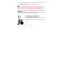
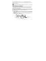
« Instant Transmission+» is the up and coming state-of-the-art new
wireless transmission technology, exclusively designed and developed by
LA CROSSE TECHNOLOGY.
“IT +” offers you an immediate update of all your outdoor data measured
from the transmitters: follow your climatic variations in real-time!
72
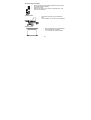
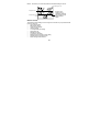
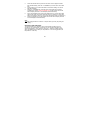
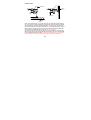
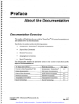
FEATURES:
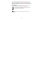
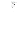
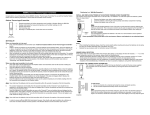
The Multifunctional Weather Station
Foldout stand I
Hanging hole
Battery
compartment
cover
LCD
Function keys
•
•
•
•
•
•
•
•
•
•
Foldout stand II
Time display (manual setting)
12/24 hour time display
Calendar display (weekday, date, month, year)
Time alarm function
Weather forecasting function with 3 weather icons and weather tendency
indicator
Indoor temperature display in °C/ºF
Outdoor temperature display in °C/ºF
Outdoor Humidity display as RH%
Dew point displayed in °C or °F
Wind gust displayed in km/h, mph, m/s
73
•
•
•
•
•
•
•
•
•
•
•
•
•
•
•
•
•
24-hour and total rainfall displayed in mm or inch
Display Max / Min value of outdoor temperature, outdoor humidity, Dew point,
Wind chill, and Relative pressure, with time & date of recording
Display max wind speed, max gust, max 24h rainfall and total rainfall with time
& date of recording
Low/High outdoor temperature, outdoor humidity and high wind speed alarm
Relative air pressure displayed in hPa or inHg
Air pressure tendency indicator for the past 12 hour (bargraph format)
LCD contrast selectable
Low battery indicator
Wind direction displayed in 16 steps
Wind speed displayed in km/h, mph or m/s, and Beaufort scale
Wind chill displayed in °C of °F
Manual reset of outdoor temperature/ humidity, pressure, windchill, dew point,
wind speed, gust, 24h rainfall and total rainfall data
Storm warning alarm
Buzzer on/ off selectable
Storage of 140 sets of history weather data recorded in 3-hour intervals
Wireless transmission at 868 MHz
Transmission range up to 100 metres
74
The Thermo-HygroTransmitter
•
Remote transmission of the outdoor temperature and humidity to
the Weather Station at 868 MHz
•
Showerproof casing
•
Wall mounting case (to be mounted in a sheltered place. Avoid
direct rain and sunshine)
The Wind Sensor
•
•
Connected to the thermo-hygro transmitter by
cable
Can be installed onto a mast or a horizontal panel
The Rain Sensor
•
•
Remote transmission of the rainfall data to
the Weather Station at 868 MHz
To be mounted onto a horizontal panel
75
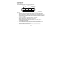
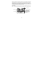
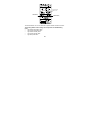
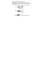
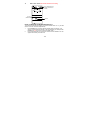
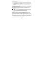
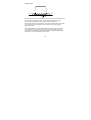
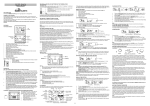
SETTING UP:
Wireless transmission at
868 MHz – Rain sensor
to weather station
Weather station
Wireless transmission at
868 MHz - thermo-hygro
transmitter to weather
station
Rain sensor
Wind sensor
Cable connection
between the wind sensor
and the thermo-hygro
transmitter
Note:
When putting the Weather Station into operation, it is important to perform in close
proximity (e.g. on a table) a complete wiring and set-up of the system. This step is
important to test all components for correct function before placing and mounting
76
them at their final destinations (See Positioning below). Spin the wind vane and tip
the rain gauge to test.
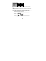
Unwind the cables of the Wind sensor. Connect the Wind sensor to the Thermo1.
hygro transmitter by plugging the connector heads into the sockets of the
Thermo-hygro transmitter. Cord should “click” into place.
Socket for wind
sensor
2.
3.
First insert the batteries into the Thermo-hygro transmitter and Rain sensor (see
“How to install and replace the batteries into the Thermo-hygro
transmitter“ & How to install and replace batteries into the Rain sensor
below).
Then insert the batteries into the Weather Station (see “How to install and
replace the batteries into the Weather Station” below). Once the batteries
are installed, all segments of the LCD will light up briefly and a short signal
tone will be heard. It will then display the time as 00:00, the date as 1.1.05, the
weather icons, and air pressure value. "- - -" will be shown for outdoor data.
77
4.
5.
6.
4.
5.
Afterwards, the Weather Center will start receiving data from the transmitter.
The transmission reception icon will be blinking to indicate that the station is
trying to get the thermo-hygro transmitter data. The outdoor temperature,
humidity, wind data should then be displayed on the Weather Center. If this
does not happen after 45 seconds, the batteries will need to be removed from
all units. You will have to start again from step 2.
The transmitter reception icon is now blinking again to indicate that the station is
trying to get the rain sensor data. It will stop blinking once the rain sensor has
been detected. If this does not happen after 45 seconds, you will need to start
again from step 2.
You may need to check the cable for correct connection and all the components
for correct function by manually turning the wind-gauge by moving the windvane; tilting the rain sensor to hear the impact of the internal moving seesaw,
etc. (see Positioning below).
Time and date shall be manually set (See Manual Setting below).
After the Weather Station has been checked for correct function with regard to
the above points and found fit, the initial set up of the weather station system is
finished and the mounting of the system components can take place. It must be
ensured however that all components work properly together at their chosen
mounting or standing locations. If e.g. there appear to be problems with the 868
MHz radio transmission, they can mostly be overcome by slightly changing the
mounting locations.
Note:
The radio communication between the receiver and the transmitter in the open field
reaches distances of max 100 metres, provided there are no interfering obstacles
such as buildings, trees, vehicles, high voltage lines, etc.
78
8.
Radio interferences created by PC screens, radios or TV sets can in some
cases entirely cut off radio communication. Please take this into consideration
when choosing standing or mounting locations.
Note :
•
After batteries are installed in the transmitter, install the batteries in the
weather center to receive the signal from the transmitters as soon as
possible. If the weather center is powered more than 5 hours after the
transmitter is powered, the weather center will never receive signal
successfully from the transmitters. In this case, user will need to reinstall
the batteries from all the transmitters to redo set-up procedure.
•
After batteries are installed, there will be synchronization between weather
center and the transmitters. At this time, the signal reception icon will be
blinking. When the signal is successfully received by the weather center,
the icon will be switched on. (If it is not successful, the icon will not be
shown in LCD) So the user can easily see whether the last reception was
successful (icon on) or not (icon off). On the other hand, the short blinking
of the icon shows that a reception is in progress.
Transmitter signal
reception icon
HOW TO INSTALL AND REPLACE THE BATTERIES INTO THE WEATHER
STATION
79
The Weather Station works with 3 x AA, IEC LR6, 1.5V
batteries. When the batteries need to be replaced, the low
battery symbol will appear on the LCD.
To install and replace the batteries, please follow the
steps below:
1.
Remove the battery compartment cover.
2.
Insert the batteries observing the correct polarity
(see the marking in the battery compartment).
3.
Replace the battery cover.
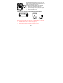
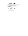
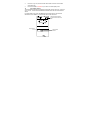
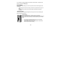
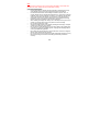
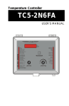
HOW TO INSTALL AND REPLACE BATTERIES INTO THE RAIN SENSOR
Figure 1
Figure 2
Figure 3
The rain sensor works with 2 x AAA, IEC LR3, 1.5V Alkaline batteries. To install and
replace the batteries, please follow the steps below:
1.
Press tabs back to unlock rain sensor cover. (Figure 1)
2.
Lift rain sensor cover to access battery compartment. (Figure 2)
80
3.
4.
Insert the batteries, observing the correct polarity (see the marking in the battery
compartment). (Figure 3)
Replace the battery cover and the rain cover onto the unit.
Note:
In the event of changing batteries in any of the units, all units need to be reset by
following the setting up procedures. This is because a random security code is
assigned by the rain sensor at start-up and this code must be received and stored by
the Weather Center in the first several minutes of power being supplied to it.
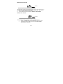
HOW TO INSTALL AND REPLACE THE BATTERIES INTO THE THERMO-HYGRO
TRANSMITTER
The outdoor Thermo-hygro transmitter works with 2 x AA IEC LR6, 1.5V batteries. To
install and replace the batteries, please follow the steps below:
1.
2.
3.
4.
Uninstall the rain cover of the transmitter.
Remove the battery compartment cover.
Insert the batteries, observing the correct polarity (see the
marking in the battery compartment).
Replace the battery cover and the rain cover onto the unit.
Note:
81
In the event of changing batteries in any of the units, all units need to be reset by
following the setting up procedures. This is because a random security code is
assigned by the transmitter and rain sensor at start-up and this code must be received
and stored by the Weather Station in the first several minutes of power being supplied
to it.
BATTERY CHANGE:
It is recommended to replace the batteries in all units every 24 months to ensure
optimum accuracy of these units. (Battery life –see Specifications)
Please participate in the preservation of the environment. Return
used batteries to an authorised depot.
Note:
The stored History record will not be kept after the battery change is done on the
weather station.
82
FUNCTION KEYS:
Weather Station:
The Weather Station has 5 easy-to-use function keys.
Set key
ALARM key
+ key
MIN/MAX key
HISTORY key
SET key
•
Press and hold to enter manual setting modes: LCD contrast, Manual time
setting, 12/24 hour time display, Calendar setting, ºC/ ºF temperature unit, Wind
speed unit, Rainfall unit, Pressure unit, Relative pressure reference setting,
Weather tendency threshold setting, Storm warning threshold setting and Storm
Alarm On/ Off setting
•
Press to toggle between the display of Mode 1 or Mode 2:
Mode1: "Wind speed + outdoor temp + rel. pressure"
Mode 2: "Gust + Dew Point temp + rainfall"
(Mode 2 displayed will be shown for 30 seconds. Then it will return to
normal display automatically.)
•
In normal display mode, press and hold to switch on/ off the Buzzer
•
In the weather alarm setting mode, press and hold to adjust different alarm
value and switch the alarm On/ Off
•
Press to activate the reset mode when max or min record is shown
83
•
Stop the alarm during the time alarm or weather alarm ringing
+ key
•
•
•
•
•
•
In display Mode 1, press to toggle between the display of Preset alarm time,
date, weekday + date, Indoor temp, or second in the time display
In display mode 2, press to toggle between the display of Rel. Pressure, 24 hour
rainfall and Total rainfall
Press to adjust (increase) the level of different settings
Stop the alarm during the time alarm or weather alarm ringing
Press to confirm to reset the max/min record
Press to reset the total rainfall amount to 0
HISTORY key
•
Press to display the weather data history records
•
Stop the alarm during the time alarm or weather alarm ringing
•
Press to exit manual setting mode and alarm setting mode
ALARM key
•
Press to enter the time alarm and weather alarm setting mode
•
Confirm particular alarm setting
•
Press to exit the manual setting mode
•
Stop the alarm during the time alarm or weather alarm ringing
•
Press to exit max/ min record display mode
MIN/MAX key
•
Press to display minimum and maximum records of various weather data
•
Press to adjust (decrease) the level of different settings
84
•
Stop the alarm during the time alarm or weather alarm ringing
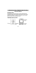
LCD SCREEN
The LCD screen is split into 5 sections displaying the following information:
1.
Time and date/ indoor temp/ second
2.
Wind data
3.
Outdoor temperature, Dew point and humidity,
4.
Air pressure, Rainfall data
5.
Air pressure history and Weather forecast icon.
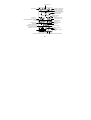
85
Time alarm icon
Calendar, indoor temp.,
or alarm time display
Time display
Buzzer off indicator
Wind direction display
and wind speed in
Beaufort scale
Wind speed Hi
alarm icon
Wind speed or gust
in mph, km/h or m/s
Wind Chill
in °F or ° C
Outdoor temperature or dew point
in °F or ºC
Outdoor relative
humidity in %
Outdoor temp.
alarm icon
Outdoor Humidity
alarm icon
Transmitter signal
reception icon
Weather tendency
indicator
Weather forecast
icon
Relative air pressure
display in inHg or hPa, or
total and 24h rainfall
display in inch or mm
Air pressure
histogram
Low battery Indicator (Thermo-hygro) Low battery Indicator (rain sensor)
86
#When the signal from the transmitter/ or Rain sensor is successfully received by the
Weather Station, this icon will be switched on. (If not successful, the icon will not be
shown on the LCD). User can therefore easily see whether the last reception was
successful (“ON” icon) or not (“OFF” icon). On the other hand, the short blinking of the
icon shows that a reception is being done at that time.
*In nomal display user may press the SET key shortly to toggle between Mode1 and
Mode 2 display:
Mode 1 : Wind speed, outdoor temperature and relative pressure reading are shown.
Wind speed icon
Outdoor temp
icon
In Mode 1, this reception
icon is showing the
condition of the
reception of the signal
from Thermo-hygro
transmitter
Rel Pressure
icon
87
Mode 2 : Wind Gust, Dew Point temperature and Rainfall reading are shown.
Wind gus icon
Dew point icon
In Mode 2, this
reception icon is
showing the condition
of the reception of the
signal from Rain
sensor
Rainfall icon
MANUAL SETTING:
The following manual settings can be changed once the SET key is pressed and hold
for about 3 seconds:
•
LCD contrast setting
•
Manual time setting
•
12/24 hour time display
•
Calendar setting
•
°C/ °F temperature unit setting
•
Wind speed unit
•
Rainfall unit setting
•
Air pressure unit setting
•
Relative pressure reference value setting
•
Weather tendency threshold value
•
Storm warning threshold value
88
•
Storm alarm On/ Off setting
LCD CONTRAST SETTING
Digit flashing
The LCD contrast can be set within 8 levels, from "LCD 1" to "LCD8" (default setting
is LCD 5):
1.
Press the SET key, the contrast level digit will start flashing.
2.
Use the + or MIN/MAX key to adjust the level of contrast.
3.
Confirm with the SET key and enter the MANUAL TIME SETTING.
MANUAL TIME SETTING:
You then may manually set the time of the clock by following the steps below:
Minutes flashing
Hour
flashing
1.
2.
The hour digit will start flashing.
Use the + or MIN/MAX key to set the hour.
89
3.
4.
5.
Press the SET key to switch to the minutes. The minute digit will start flashing.
Use the + or MIN/MAX key to set the minute.
Confirm the time with the SET key and enter the 12/24 HOUR TIME DISPLAY
SETTING.
12/24 HOUR TIME DISPLAY SETTING:
Digit flashing
The time can be set to view as 12-hour or 24-hour format. The default time display
mode is “24-h”. To set to “12-h” time display:
1.
Use the + or MIN/MAX key to toggle the value.
2.
Confirm with the SET key and enter the CALENDAR SETTING.
CALENDAR SETTING:
"Date. Month." (for 24h time display)
"Month. Date." (for 12h time display)
Year
90
The date default of the Weather Station is 1. 1. of year 2005. The date can be set
manually by proceeding as follows.
1.
The year digit starts flashing.
2.
Use the + or MIN/MAX key to set the year. The range runs from "00" (2000) to
"99" (2099).
3.
Press the SET key to confirm the year and enter the month setting. The month
digit will start flashing.
4.
Use the + or MIN/MAX key to set the month.
5.
Press the SET key to confirm the month and enter the date setting mode. The
date digit will start flashing.
6.
Use the + or MIN/MAX key to set the date.
7.
Confirm all calendar settings with the SET key and enter the °C/°F
TEMPERATURE UNIT SETTING.
°C/°F TEMPERATURE UNIT SETTING
Flashing
The temperature display can be selected to show temperature data in °C or °F.
(default °C)
1.
The temperature unit is flashing
2.
Use the + or MIN/MAX key to toggle between “°C” or “°F”.
Confirm with the SET key and enter the WIND SPEED UNIT SETTING
91
WIND SPEED UNIT SETTING
Flashing
The wind speed unit can be set as km/h (kilometre per hour), mph (mile per hour) or
m/s (metre per second). The default unit is km/h.
1.
Use the + or MIN/MAX key to toggle between the unit “km/h”, “mph” or “m/s”
2.
Confirm with the SET key and enter the RAINFALL UNIT SETTING.
RAINFALL UNIT SETTING
Flashing
The total rainfall unit can be set as mm or inch. The default unit is mm.
1.
Use the + or MIN/MAX key to toggle between the unit “mm” or “Inch”
2.
Confirm the unit with the SET key and enter the RELATIVE AIR
PRESSURE UNIT SETTING
92
RELATIVE AIR PRESSURE UNIT SETTING
Flashing
The relative air pressure can be set as hPa of inHg. The default unit is hPa.
1.
Use the + or MIN/MAX key to toggle between the unit “hPa" or “inHg”
2.
Confirm the unit with the SET key and enter the RELATIVE PRESSURE
REFERENCE VALUE SETTING.
RELATIVE PRESSURE REFERENCE VALUE SETTING
Note:
The default reference pressure value of the barometer is 1013 hPa when batteries are
first inserted. For an exact measurement, it is necessary to first adjust the
barometer to your local relative air pressure (related to elevation above sea
level). Ask for the current atmospheric pressure of your home area (Local weather
service, www, optician, calibrated instruments in public buildings, airport).
The relative air pressure can be manually set to another value within the range of 919
to 1080 hPa (27.14 to 31.90 inHg) for a better reference.
Flashing
93
1.
2.
3.
The current relative pressure value will start flashing
Use the + or MIN/MAX key to increase or decrease the value. Keep holding the
key will allow the value to increase faster.
Confirm with the SET key and enter the WEATHER TENDENCY THRESHOLD
VALUE SETTING.
Note:
This calibration facility is useful for those users living at various elevations above sea
level, but wanting their air pressure display to be based on sea level elevation.
WEATHER TENDENCY SENSITIVITY LEVEL SETTING
blinkend
You may select a definite switching sensitivity value, 2, 3, 4 hPa for the change in the
display of weather icons. This represents the "sensitivity" of the weather forecast (the
smaller the value selected, the more sensitive the weather forecast). The default
value is 3 hPa. Select lower numbers for high humidity areas, i.e. Oceanside. Select
high numbers for arid areas, i.e. desert.
94
1.
2.
3.
The sensitivity value will start flashing
Use the + or MIN/MAX key to select the value.
Confirm with the SET key and enter the STORM WARNING SENSITIVITY
SETTING.
STORM WARNING THRESHOLD VALUE SETTING
You may also define a switching threshold value for the Storm warning display at a
decrease of air pressure from 3 hPa to 9 hPa over 6 hours (Default 5 hPa).
blinkend
1.
2.
3.
The threshold value will start flashing.
Use the + or MIN/MAX key to select the value.
Confirm with the SET key and enter the STORM ALARM ON/ OFF SETTING.
STORM ALARM ON/ OFF SETTING
You may also choose to switch On or Off the acoustic Storm warning alarm (Default
OFF).
1.
The digit "AOF" will start flashing.
2.
Use the + or MIN/MAX key to switch On or Off the alarm. ("AOF" = OFF;
"AON" = On)
3.
Confirm with the SET key and the normal display mode will be shown.
95
Flashing
Note:
In case a storm warning alarm is activated, the downward weather tendency arrow will
be flashing. (Also see clause WEATHER TENDENCY INDICATOR below)
TO EXIT THE MANUAL SETTING MODE
To exit the manual setting anytime during the manual setting modes, press the
ALARM key (or HISTORY key) anytime or wait for the automatic timeout. The mode
will return to the normal time display.
TIME ALARM SETTING
The alarm time can be set by the use of the ALARM and SET key.
1.
Press the ALARM key once. The time digits are shown at the top right of the
LCD.
Alarm time digit
Alarm-On icon
96
2.
3.
4.
5.
6.
Press and hold the SET key for about 2 seconds. The hour digit of the alarm
time will start flashing. Press the + or MIN/MAX key to set the hour of the alarm
time.
Press the SET key to confirm and advance to the minute setting. The minute
digit will be flashing.
Press the + or MIN/MAX key to set the minute of the alarm time. Press the
ALARM key to confirm. Press the HISTORY key or wait for about 30 seconds
and the display will return to normal display mode automatically.
In the normal display mode, press the ALARM once key to go to the time alarm
setting mode again. Then press shortly the SET key to switch on or off the time
alarm. (The showing of the icon ((())) means that the time alarm is switched on.)
Press the HISTORY key or wait for about 30 seconds and the display will return
to normal display mode automatically.
Note:
The alarm ringing duration is 2 minutes. To stop the alarm, press any key during the
alarm ringing.
WEATHER ALARM OPERATIONS
The Weather alarms are settable for when certain weather conditions are met
according to your requirements. For example, you can set the thresholds for the
outdoor temperature to +40°C (high) and -10°C (low) , whilst only enabling the high
alarm and disabling the low alarm (i.e. temperatures <-10°C won’t trigger alarm, but
temperatures >+40°C will).
97
High wind speed
Alarm-On icon
Outdoor temp
Alarm-On icon
Outdoor humidity
Alarm-On icon
The Weather Station can be set to alert when a specific weather condition is reached.
The following Weather Alarm settings can be adjusted in the ALARM setting
mode.
•
High outdoor temperature alarm
•
Low outdoor temperature alarm
•
High outdoor humidity alarm
•
Low outdoor humidity alarm
•
High wind speed alarm
98
Default alarm values:
Low
Temperature
High
Relative
Low
Humidity
High
Wind speed
High
0°C
40°C
45%
70%
100 km/h
HIGH AND LOW OUTDOOR TEMPERATURE ALARM SETTING
Note:
The High and Low outdoor temperature alarm can be set On/ Off independently,
according to your needs.
Set the Outdoor temperature alarm value (High or Low alarm value) :
1.
In the normal display mode, press the ALARM key twice. The High Outdoor
Temperature alarm display will be shown.
High alarm
icon
Alarm-On
icon
99
2.
3.
4.
5.
6.
7.
Press and hold the SET key for about 2 seconds. The temperature digit will
start flashing. Press the + or MIN/MAX key to set the high outdoor temp alarm
value. (Keep holding the key will allow the value to increase faster.)
Press the ALARM key to confirm the setting. The digit will stop flashing. Press
the SET key to switch on or off the alarm. (The showing of the icon ((()))
means that the alarm is switched on.)
Press the ALARM key once. The Low Outdoor Temperature alarm display will
be shown.
Press and hold the SET key for about 2 seconds. The temperature digit will
start flashing. Press the + or MIN/MAX key to set the low outdoor temp alarm
value. (Keep holding the key will allow the value to increase faster.)
Press the ALARM key to confirm the setting. The digit will stop flashing. Press
the SET key to switch on or off the alarm. (The showing of the icon ((()))
means that the alarm is switched on.)
Press the HISTORY key or wait for about 30 seconds and the display will
return to normal display mode automatically.
In case the temperature value meets the condition for high alarm or low alarm, the
value will be blinking, along with the corresponding icon ("HI AL"/ "LO AL").
And the buzzer will ring for 2 minutes. User then may press any key to stop the ring.
User may quit the alarm setting and return to the normal display mode by pressing the
HISTORY key.
100
HIGH AND LOW OUTDOOR HUMIDITY ALARM SETTING
Note:
The High and Low outdoor humidity alarm can be set On/ Off independently according
to your needs.
Set the Outdoor humidity alarm value (High or Low alarm value):
1.
In the normal display mode, press the ALARM key four times. The High
Outdoor Humidity alarm display will be shown.
2.
3.
4.
5.
Press and hold the SET key for about 2 seconds. The humidity digit will start
flashing. Press the + or MIN/MAX key to set the high outdoor humidity alarm
value.
Press the ALARM key to confirm the setting. The digit will stop flashing. Press
the SET key to switch on or off the alarm. (The showing of the icon ((()))
means that the alarm is switched on.)
Press the ALARM key once. The Low Outdoor humidity alarm display will be
shown.
Press and hold the SET key for about 2 seconds. The humidity digit will start
flashing. Press the + or MIN/MAX key to set the low outdoor humidity alarm
value.
101
6.
7.
Press the ALARM key to confirm the setting. The digit will stop flashing. Press
the SET key to switch on or off the alarm. (The showing of the icon ((()))
means that the alarm is switched on.)
Press the HISTORY key or wait for about 30 seconds and the display will
return to normal display mode automatically.
In case the humidity value meets the condition for high alarm or low alarm, the value
will be blinking, along with the corresponding icon ("HI AL"/ "LO AL"). And the buzzer
will ring for 2 minutes. User may press any key to stop the sound.
WIND SPEED ALARM SETTING
The High wind speed alarm can be set by following the steps below.
1.
In the normal display mode, press the ALARM key six times. The High wind
speed alarm display will be shown.
2.
3.
4.
Press and hold the SET key for about 2 seconds. The wind speed digit will
start flashing. Press the + or MIN/MAX key to set the high wind speed alarm
value.
Press the ALARM key to confirm the setting. The digit will stop flashing. Press
the SET key to switch on or off the alarm. (The showing of the icon ((()))
means that the alarm is switched on.)
Press the ALARM key once to return to the normal display mode.
102
In case the wind speed exceeds the condition for high wind speed alarm, the value
will be flashing, along with the corresponding high alarm icon ("HI AL"). And the
buzzer will ring for 2 minutes. User may press any key to stop the sound.
HYSTERESIS
To compensate for fluctuation of the measured data, which may cause the weather
alarm to sound constantly if the measured reading is close to your set level, a
hysteresis function has been implemented for each weather alarm. For example, if the
high temperature alarm is set to +25°C and the curr ent value moves to +25°C, the
alarm will be activated (if it has been enabled). Now when the temperature drops to
+24.9°C or below and thereafter again increases to beyond +25°C, the data will be
blinking, but no alarm will be activated. It has to drop to below +24°C (with a pre-set
hysteresis of 1°C) so that the alarm can be produce d again. Hysteresis values for the
various weather data types are given in the following table:
Weather data
Temperature
Humidity
Wind speed
Hysteresis
1°C
3% RH
5 km/h
Note:
The temperature, humidity or wind data will keep on flashing even after a key has
been pressed to stop the alarm or buzzer has been switched off, to indicate that the
current weather condition is out of the pre-set limit(s)
103
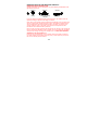
WEATHER FORECAST AND WEATHER TENDENCY:
WEATHER FORECASTING ICONS:
Weather forecasting icons are displayed in any of the following combinations at the
right bottom part of LCD:
TENDENCY
Sunny
TENDENCY
TENDENCY
Cloudy with sunny
intervals
Rainy
For every sudden or significant change in the air pressure, the weather icons will
update accordingly to represent the change in weather.
(Every time a new average pressure value has been obtained (once per minute), this
value is compared with an internal reference value. If the difference between these
values is bigger than the selected weather tendency sensitivity, the weather-icon
changes, either for worse or for better. In this case, the current pressure value
becomes the new weather tendency reference.)
If the icons do not change, either the air pressure has not changed or the change has
been too small for the Weather Center to register. So you may adjust the "sensitivity"
of the pressure change checking in the setting mode –see WEATHER TENDENCY
SENSITIVITY VALUE SETTING above.
However, if the icon displayed is a sun or raining cloud, there will be no change of
icon if the weather gets any better (with sunny icon) or worse (with rainy icon) since
the icons are already at their extremes.
104
The icons displayed forecasts the weather in terms of getting better or worse and not
necessarily sunny or rainy as each icon indicates. For example, if the current weather
is cloudy and the rainy icon is displayed, it does not mean that the product is faulty
because it is not raining. It simply means that the air pressure has dropped and the
weather is expected to get worse but not necessarily rainy.
Note:
After setting up, readings for weather forecasts should be disregarded for the next 4860 hours. This will allow sufficient time for the Weather station to collect air pressure
data at a constant altitude and therefore result in a more accurate forecast.
Common to weather forecasting, absolute accuracy cannot be guaranteed. The
weather forecasting feature is estimated to have an accuracy level of about 75% due
to the varying areas the Weather Center has been designed for use. In areas that
experience sudden changes in weather (for example from sunny to rain), the Weather
Center will be more accurate compared to use in areas where the weather is stagnant
most of the time (for example mostly sunny).
If the Weather Center is moved to another location significantly higher or lower than
its initial standing point (for example from the ground floor to the upper floors of a
house), discard the weather forecast for the next 48-60 hours, as the Weather Center
may mistake the new location as being a possible change in air-pressure when really
it is due to the slight change of altitude.
THE WEATHER TENDENCY INDICATOR
Working together with the weather icons are the weather tendency indicators (the
upward and downward arrows located on the right hand side of the weather girl icon).
When the indicator points upwards, it means that the air-pressure is increasing and
the weather is expected to improve, but when indicator points downwards, the air-
105
pressure is dropping and the weather is expected to become worse.
Therefore, user may see how the weather has changed and is expected to change.
For example, if the indicator is pointing downwards together with cloudy icons, it
means that the last noticeable change in the weather was when it was sunny (the
sunny icon only). Therefore, the next change in the weather will be the cloudy icons
since the indicator is pointing downwards.
Note:
Once the weather tendency indicator has registered a change in air pressure, it will
remain permanently visualized on the LCD.
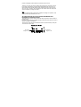
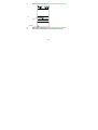
AIR PRESSURE HISTORY (ELECTRONIC BAROMETER WITH
BAROMETRIC PRESSURE TREND)
The bottom section of the LCD also shows the relative air pressure value and the air
pressure history.
Depending on programming conditions, display of the history of air pressure in form of
a graph consisting of vertical bars.
The bar graph of the electronic barometer shows the air pressure history of the past
12 hours in five 3-hour steps.
Air pressure
changes in inHg
Air pressure
changes in hPa
106
The horizontal axis represents the last 12 hours air pressure recording (-12, -9, -6, -3
and 0 hour). The bars are plotted at each of the 5 steps and give the trend over the
recorded period. The scale on the right compares the result. The "0" in the middle of
this scale determines the current air pressure.
The vertical axis represents the air pressure changes in hPa (+4, +2, 0, -2, -4. “0”
represents the current air pressure). The newly measured pressure was compared to
the previously recorded pressure reading. The pressure change is expressed by the
difference between the current ("0h") and the past readings in division of ±2 hPa or
±0.06 inHg. If the bars are rising it indicates that the weather is getting better due to
an increase in air pressure. If the bars go down it indicates a drop of the air pressure
and the weather is expected to get worse from the present time "0".
At every full hour the current air pressure is used as a basis for the display of a new
graph bar. The existing graph is then moved one column to the left.
Note:
For accurate barometric pressure trend, the Weather Station should operate at the
same altitude. For example, it should not be moved. Should the unit be moved, for
instance from the ground to the second floor of the house, the readings for the next
48-60 hours shall be discarded.
WIND DIRECTION AND WIND SPEED MEASUREMENT
In normal display mode, the second section of the LCD shows the following wind data.
•
Wind direction (shown on the a compass scale of 16 divisions) and wind speed/
gust in Beaufort scale
•
Wind chill in °C or °F
•
Wind Speed in km/h, mph or m/s
107
•
Gust in km/h, mph or m/s (displayed when in Mode 2, by pressing the SET key
shortly)
Text showing Wind
speed in Beaufort scale
bft
Pointer indicates the
currently detected wind
direction
HIAL
This alarm symbol
indicates that the
alarm is set On
Wind chill
Wind speed or Gust will
be shown
RAINFALL MEASUREMENT
The total rainfall and 24 hour rainfall measurement is displayed in the fourth section of
the LCD, in the unit of mm or inch.
To View the 24 hour rainfall or the Total rainfall reading:
1.
In normal display press SET key once and the display will shift to Mode 2.
2.
Press + key consecutively key to toggle between the 24 hour rainfall, Total
rainfall and Rel. pressure reading.
108
24 hour
rainfall icon
24h
24 hour rainfall
amount
Total rainfall
icon
Total rainfall
amount
VIEWING THE HISTORY DATA
The weather station can store up to 140 sets of weather data which are recorded
automatically at 3-hour intervals after the weather station is powered up, at the
nearest time of 0:00, 03:00, 06:00, 09:00, 12:00, 15:00, 18:00 and 21:00. For
instance, if user has manually set the time as 14:52 after installing batteries, the first
history record will be made at the coming 15:00 automatically. Then the second
record will be on 18:00 and so on.
Each weather record includes the Wind direction, Wind speed/ gust in Beaufort scale,
Wind chill temperature, wind speed/gust, dew point, Outdoor temp and humidity,
relative pressure, 24-hour rainfall and total rainfall, pressure history and weather
tendency. Also, the time and date of recording will be displayed.
109
Note:
In order to acquire the correct time of recording of the history records, you shall
manually set the current time as soon as installing batteries to the weather station.
Afterwards, you should avoid changing the pre-set time as it will also alter the
recorded "time of recording" of each history record, which may lead to confusion.
To view the weather history:
1.
In normal display, press the HISTORY key. The latest weather record will be
shown with the date and time of recording. The "HISTORY" icon will be
displayed at the bottom of the LCD.
2.
When viewing History records, user may shift to see the Mode 1 or Mode 2
data by pressing the SET key.
(Mode 1: with wind speed + outdoor Temp + Rel. pressure;
Mode 2 : with wind gust + Dew point + rainfall data)
Note: If user wants to choose to view total rainfall or 24-hour rainfall in history records,
he shall first in normal display choose to show the particular rainfall data, the press
History key and SET key to view the particular rainfall data in History records.
110
HISTORY icon
3.
When viewing History records, press MIN/ MAX to view older records.
(Press MIN/MAX and + key to view "Previous" and "Next" record respectively.
The records are made at 3-hour intervals)
Note:
•
•
The stored history records will not be retained after battery change or whenever
battery is removed.
The total rainfall value will be exhibited in whole number (no decimal place) in
the history record.
111
VIEWING THE MAXIMUM/ MINIMUM WEATHER DATA
The weather station will record the maximum and minimum value of the various
weather data with time and date of recording automatically. The following stored
maximum and minimum weather data can be viewed by pressing the MIN/MAX key in
normal display mode.
1.
Min outdoor temperature with the date and time of recording
Time and date
or recording
MIN outdoor
temperature
value
MIN icon
2.
Max outdoor temperature with the date and time of recording
112
3.
Min dew point temperature with the date and time of recording
DATE
DEW POINT
MIN Dew Point
temp
MIN icon
4.
5.
Max dew point temperature with the date and time of recording
Min outdoor humidity with the date and time of recording
113
6.
Max outdoor humidity with the date and time of recording
Time and date
or recording
MAX outdoor
humidity value
MAX icon
114
7.
Min Wind chill temperature with the date and time of recording
Time and date
or recording
MIN wind chill
value
MIN icon
8.
9.
Max Wind chill temperature with the date and time of recording
Min Relative pressure with the date and time of recording
115
10.
Max Relative pressure with the date and time of recording
Time and date
or recording
MAX relative
pressure value
MAX icon
116
11.
Maximum wind speed with the date and time of recording
Time and date
or recording
MAX wind
speed value
MAX icon
117
12.
Maximum Gust with the date and time of recording
Time and date
or recording
GUST
MAX icon
118
MAX Gust value
13.
Max 24 hour rainfall with the date and time of recording
The 24 rainfall value is
counted from this time
and date
24 hour
rainfall icon
24 h
24 hour rainfall
amount
RESET THE MAXIMUM AND MINIMUM WEATHER DATA
To reset the aforementioned maximum or minimum weather data 1. to 13., you shall
need to reset each of the data independently.
1.
Press MIN/MAX key to show the desired weather data. For instance, if you
want to reset the minimum humidity, in the normal display you shall press the
MIN/MAX key five times to show the min humidity value.
2.
Press and hold the SET key for about 2 seconds, then the "RESET" icon will
appear at the bottom part of the LCD.
119
3.
4.
Press the + key once, then the stored value will be reset to the current value
and current time.
Press the ALARM or HISTORY key to return to normal display mode.
14.
Total rainfall amount
The total rainfall measurement is displayed in the fourth section of the LCD, in the unit
of mm or inch. It shows the total rainfall accumulated since last reset of the weather
station.
In normal display mode, press the MIN/MAX key fourteen times to show the total
rainfall value. The "RESET" icon will also be shown at the same time.
The total rainfall value is
counted from this time and
date
Total rainfall
icon
Total rainfall
amount
120
To reset the rainfall reading, press the + key once when the Rainfall value and
"Reset" icon is shown. Then the total rainfall amount will be reset to 0, and the time
updated to current time.
Note:
After power up, the time and date and total rainfall is displayed as "- - -". After time is
adjusted manually, the set time will be shown.
SWITCHING ON/OFF THE BUZZER
User may choose to turn off the buzzer so that when the time alarm is switched on
and activated, the buzzer will not sound but we can still see the alarm icon ((()))
flashing on the LCD for time alarm.
On the other hand, when the buzzer is turned off and any weather alarm is activated,
the particular weather digits will flash to show user that the weather condition is being
out of the preset threshold value, yet the buzzer will not sound.
To switch off the buzzer:
1. In normal display mode, press and hold the SET key until the icon "BUZZER OFF"
is shown at the right side above the Wind direction scale. The LCD will change to
setting mode.
2. Press ALARM or HISTORY key once to return to the normal display mode. The
"BUZZER OFF" icon will still be shown.
BUZZER OFF icon
121
To re-enable the buzzer:
1.
When the BUZZER OFF icon is shown on LCD, press and hold the SET key
until the BUZZER OFF icon disappears.
2.
Press ALARM or HISTORY key once to return to the normal display mode. The
"BUZZER OFF" icon will no longer be shown. Then the alarm will sound
normally.
LOW BATTERY INDICATOR
The low battery indicator of the weather station and the transmitter will be displayed at
the top and bottom portion of the LCD respectively when the battery power is low. It is
recommended to replace the batteries in all units on an annual basis to ensure
optimum accuracy of the system.
Note:
•
•
After battery change, both the Weather Station and the transmitters need to be
reset (see note ”Setting up”)
The History data record will be clear after the battery change.
OUTDOOR TRANSMITTER 868 MHz RECEPTION CHECK
The outdoor temperature, humidity, wind data are transmitted from thermo-hygro
transmitter every 4.5 seconds; the rainfall data are transmitted from the rain sensor
every 6.25 seconds. The receiver will be synchronized to the thermo-hygro transmitter
and rain sensor then. The transmission range (supposedly up to about 100 metres) of
the thermo-hygro transmitter/ rain sensor may be affected by the ambient temperature.
At cold temperatures the transmitting distance may be decreased. Please keep this in
mind when placing the transmitter and the rain sensor.
122
If (1) the outdoor data are not being received within 30 seconds after setting up; (2)
the outdoor display always show “- - -“ on the outdoor display; or (3) the reception
icon of thermo-hygro transmitter (Mode 1) and rain sensor (Mode 2) is not displayed
on the display, user shall check the following points:
1.
2.
3.
4.
5.
The distance of the Weather Station or transmitter/ rain sensor should be at
least 1.5 to 2 metres away from any interfering sources such as computer
monitors or TV sets.
Avoid positioning the Weather Station onto or in the immediate proximity of
metal doors or window frames.
Using other electrical products such as headphones or speakers operating on
the same signal frequency (868 MHz) may prevent correct signal transmission
and reception.
Neighbours using electrical devices operating on the 868 MHz signal frequency
can also cause interference.
“Visibility” of weather station and transmitter (e.g. through a window) increases
the range.
Note:
When the 868 MHz signal is received, do not re-open the battery compartment cover
of either the transmitter/ rain sensor or Weather Station, as the batteries may spring
free from the contacts and force a false reset. Should this happen accidentally then
reset all units (see Setting up above) otherwise transmission problems may occur.
During normal operation, after the outdoor display shows "- - -", the weather station
will change to receive the outdoor data every 15 minutes, until the data is read. Then
the reception period for thermo-hygro transmitter will return to 4.5 seconds (6.25
seconds for rain sensor).
123
If no reception is possible despite the observation of these factors, all system units
have to be reset (see Setting up).
POSITIONING:
Prior to permanently affixing any of the units, please ensure the following points are
considered:
•
Cable lengths of the units meet with your distance requirements at the point of
fixing
•
Signals from the sensors can be received by the base station at points of
mounting
The Weather Station
The Weather Station has been designed to be hung onto wall or free standing with
the two kinds of foldout stand.
To wall mount
Choose a sheltered place. Avoid direct rain and sunshine.
Before wall mounting, please check that the outdoor temperature and
humidity values can be received from the desired locations. To wall
mount:
1.
2.
Fix a screw (not supplied) into the desired wall, leaving the
head extended out by about 5mm.
Hang the station onto the screw. Remember to ensure that it
locks into place before releasing.
124
The Thermo-hygro Sensor
Rain Cover
Main Unit
Wall Bracket
An ideal mounting place for the thermo-hygro sensor would be the outer wall beneath
the extension of a roof, as this will protect the sensor from direct sunlight and other
extreme weather conditions.
To wall mount, use the 2 screws to affix the wall bracket to the desired wall, plug in
the thermo-hygro sensor to the bracket and secure both parts by the use of the
supplied screw and ensure that the cables from the wind and rain sensors are
correctly plugged in otherwise data transmission errors could occur.
125
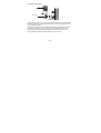
The Wind Sensor
Wind vane
Vertical
mast
Wind fan
Horizontal
panel
Firstly, check that the wind-cups and the wind-vane can rotate freely before fixing the
unit. For correct and accurate readings it is important to mount the sensor so that the
front (marked E) is pointing in East-West direction. The wind sensor should now be
mounted using the screw or cable tie provided onto a solid wall/ panel mast or mast to
allow the wind to travel around the sensor unhindered from all directions (ideal mast
size should be from diameter 16mm to 33mm). Do not over tighten.
Once the wind sensor is fixed onto the mast, connect the cable to the corresponding
thermo-hygro sensor socket so that operating power supply can be received and data
can be transmitted to the base station. Secure cord from blowing. Do not use staples.
Using PVC pipe or metal as a mast may cause static. Wood is recommended.
126
The Rain Sensor
Horizontal
panel
For best results, the rain sensor should be securely mounted onto a horizontal surface
about 1 meter above the ground and in an open area away from trees or other
coverings where rainfall may be reduced causing inaccurate readings.
When securing into place, check that rain excess will not collect and store at the base
of the unit but can flow out between the base and the mounting surface (test by
pouring clean water).
After mounting the rain sensor and placing battery, the rain sensor is now operable.
For testing purposes, very slowly pour a small amount of clean water into the rain
sensor funnel. The water will act as rainfall and will be received and displayed at the
base station i.e. when the reading interval is reached.
127
Note:
You will need to be able to access your rain gauge periodically to clean debris and
possible insect nests. Please keep this in mind when mounting.
CARE AND MAINTENANCE:
•
Extreme temperatures, vibration and shock should be avoided as these may
cause damage to the unit and give inaccurate forecasts and readings.
•
Precautions shall be taken when handling the batteries. Injuries, burns, or
property damage may be resulted if the batteries are in contact with conducting
materials, heat, corrosive materials or explosives. The batteries shall be taken
out from the unit before the product is to be stored for a long period of time.
•
Immediately remove all low powered batteries to avoid leakage and damage.
Replace only with new batteries of the recommended type.
•
When cleaning the display and casings, use a soft damp cloth only. Do not use
solvents or scouring agents as they may mark the LCD and casings.
•
Do not submerge the unit in water.
•
Special care shall be taken when handling a damaged LCD display. The liquid
crystals can be harmful to user's health.
•
Do not make any repair attempts to the unit. Return them to their original point
of purchase for repair by a qualified engineer. Opening and tampering with the
unit may invalidate their guarantee.
•
Never touch the exposed electronic circuit of the device as there is a danger of
electric shock should it become exposed.
•
Do not expose the units to extreme and sudden temperature changes, this may
lead to rapid changes in forecasts and readings and thereby reduce their
accuracy.
128
SPECIFICATIONS:
Temperature measuring range:
Indoor
: 0ºC to +59.9ºC with 0.1ºC resolution
32°F to + 139.8°F with 0.2°F resolution
(“OF.L” displayed if outside this range)
Outdoor
: -40ºC to +59.9ºC with 0.1ºC resolution
-40°F to + 139.8°F with 0.2°F resolution
(“OF.L” displayed if outside this range)
Relative humidity measuring range:
Outdoor
: 1% to 99% with 1% resolution
(“- -” displayed if < 1%, "99" displayed if ≥ 99%)
Wind speed/ gust
: 0 to 180 km/h (0 to 111.8 mph, 0 to 50 m/s)
(displayed "OF.L" when > 180 km/h)
Wind chill/ dew point
: -40ºC to +59.9ºC (-40°F to +140°F)
(displayed "OF.L" if outside this)
Relative pressure pre-set range
24h Rainfall
Total Rainfall
: 919 to 1080 hPa (27.14 to 31.90 inHg)
: 0 to 999.9 mm
: 0 to 9999 mm
Outdoor data reception
:
every 4.5 seconds (from thermo-hygro
transmitter)
every 6.25 seconds (from rain sensor)
Air pressure checking interval
Transmission range
:
:
every 15 seconds
up to 100 meters in open space
129
Power:
Weather Station
Thermo-hygro transmitter
Rain sensor
Battery life
:
Dimensions (L x W x H):
Weather Station
Thermo-hygro transmitter
Wind sensor
Rain sensor
: 3 x AA, IEC LR6, 1.5V
: 2 x AA, IEC LR6, 1.5V
: 2 x AAA, IEC LR3, 1.5V
approximately 24 months (Alkaline batteries
recommended)
: 121 x 26.3 x 190.7 mm
: 57.3 x 62 x 156.9 mm
: 250 x 145.9 x 276.2 mm
: 144 x 54.6 x 88 mm
LIABILITY DISCLAIMER
•
•
•
•
•
The electrical and electronic wastes contain hazardous substances. Disposal
of electronic waste in wild country and/or in unauthorized grounds strongly
damages the environment.
Please contact your local or/and regional authorities to retrieve the addresses
of legal dumping grounds with selective collection.
All electronic instruments must from now on be recycled. User shall take an
active part in the reuse, recycling and recovery of the electrical and electronic
waste.
The unrestricted disposal of electronic waste may do harm on public health
and the quality of environment.
As stated on the gift box and labeled on the product, reading the “User manual”
is highly recommended for the benefit of the user. This product must however
not be thrown in general rubbish collection points.
130
•
•
•
•
•
•
The manufacturer and supplier cannot accept any responsibility for any
incorrect readings and any consequences that occur should an inaccurate
reading take place.
This product is designed for use in the home only as indication of the
temperature.
This product is not to be used for medical purposes or for public information.
The specifications of this product may change without prior notice.
This product is not a toy. Keep out of the reach of children.
No part of this manual may be reproduced without written authorization of the
manufacturer.
R&TTE Directive 1999/5/EC
Summary of the Declaration of Conformity : We hereby declare that this wireless
transmission device does comply with the essential requirements of R&TTE Directive
1999/5/EC.
131