1
VGDD
Visual Graphics Display Designer
Lab Project 1
Building a GUI with VGDD
© 2015 VirtualFab
All rights reserved
Version 2.0
2015/07/04
• Index
Introduction....................................................................................................3
Prerequisites..................................................................................................3
Preliminary steps...........................................................................................3
Choosing a Folder........................................................................................3
Start MPLAB X IDE......................................................................................4
Install and configure the VGDD-Link plug-in................................................4
Create an empty MPLAB X project...............................................................4
Start the VGDD-Link plug-in.........................................................................5
Running VGDD the first time – Configure frameworks.................................5
Setting project properties..............................................................................6
1 Create a new VGDD project.......................................................................7
1.1 Saving the screen and creating the project...........................................7
1.2 Adding a Rectangle...............................................................................7
1.3 Duplicating objects................................................................................8
1.4 Adding the top and bottom texts............................................................8
1.5 Creating a new Scheme........................................................................9
1.6 Applying new scheme to all StaticTexts.................................................9
1.7 Adding the Temperature display............................................................9
1.8 Creating a Big Font scheme................................................................10
1.9 Defining Widget's Text as RAM buffer..................................................11
1.10 Adding a Picture.................................................................................11
1.11 Adding Buttons...................................................................................12
2 Running the GUI on the Development Board........................................12
2.1 Running the Wizard.............................................................................12
2.2 Compiling the MPLAB X project and running it on the DevBoard........15
3 Modifying the GUI....................................................................................15
3.1 Adding a Buttons Menu.......................................................................15
3.2 Adding button's bitmaps......................................................................15
3.3 Copying selected Widgets between screens.......................................16
3.4 Duplicating a Screen...........................................................................16
4 Designing GUI Navigation: Events Handling.........................................16
4.1 Connecting Screens............................................................................16
4.2 Testing GUI navigation by Simulating it on the Player.........................17
5 GUI development round-trip...................................................................18
5.1 Run modified GUI................................................................................18
5.2 Hand-Writing Code..............................................................................18
5.3 Using Events to change variable values..............................................19
6 End of Lab Exercise.................................................................................19
Building a GUI with VGDD
Page 2 of 19
Introduction.
In this laboratory exercise you will learn how to use VGDD to develop a Graphical User
Interface for an example application: a thermostat.
Disclaimer: no real thermostatic function will be implemented. The exercise will focus on
GUI development only.
Points covered in this exercise:
•
Multiple screens GUI design
•
Event Handling
•
MPLAB X Wizard
•
Hand-made code implementations
•
GUI development round-trip
Note: this exercise is based on the use of the PIC24FJ256DA210 Development Board with
a Powertip 480x272 WQVGA 4.3” TFT display, but it can be easily adapted for other
hardware configurations.
Prerequisites
This exercise needs
1) MPLAB X IDE version 3.0 and above
2) XC16 Compiler version 1.24 and above
3) VGDD version 9.0 and above
4) VGDD-Link MPLAB X plug-in
5) The Lab1Resources.zip contents
VGDD, VGDD-Link and Lab1Resources.zip are all available for download from VirtualFab
site.
You can have MPLAB X installed on any supported OS (Windows, Linux, MacOs), while
VGDD needs a Windows PC to run. This can be a physical PC or a Virtual Machine
(VirtualBox, Parallels, etc.).
This document refers to a Windows installation.
Preliminary steps
Choosing a Folder
The Lab Exercise needs a folder to store
•
VGDD project
•
MPLAB X project
•
Bitmaps
So let's choose a location on the drive (may be a network folder as well) and create a
Folder for the Exercise called for example VGDDLab1.
In this folder you can unzip the Bitmaps you found in the zip for the exercise.
Building a GUI with VGDD
Page 3 of 19
Start MPLAB X IDE
Install and configure the VGDD-Link plug-in
as described in “VGDD-Link plug-in for MPLAB®X User's Manual”.
Create an empty MPLAB X project
Click on the
button and proceed with the creation of a Standalone project:
Select PIC24 family and choose PIC24FJ256DA210 device:
Building a GUI with VGDD
Page 4 of 19
Select your PIC programmer tool (RealICE, PicKit3, etc.) and select the compiler to use
(XC16).
Give a name to the Project (Thermo1) and as project location, navigate to the folder you
created for your exercise.
Notice: using VGDD you are free of placing the MPLAB X project wherever you want.
Once you created the empty MPLAB X project,
Start the VGDD-Link plug-in
by clicking on the
button.
This will launch VGDD, which will automatically connect to the running MPLAB X.
If you instead are working with MPLAB X on a different OS, you'll have to start VGDD
manually as described in the VGDD-Link User's manual.
Running VGDD the first time – Configure frameworks
When launched for the first time, VGDD will ask for configuration.
In particular, paths to the frameworks (MLA Legacy, MLA or Harmony) that will be used are
to be configured.
You can re-run this phase whenever needed by clicking on the Project Settings toolbar
button
and then clicking on the
button.
This will display the Select Framework panel:
This Lab exercise is focused on the PIC24FJ256DA210 Development board, so we will
use MLA.
If you don't have MLA yet, you can click on “Get Frameworks from Microchip site” and the
browser will open on the right pages.
Download and install “Current MLA”.
At the time of writing, the latest MLA is v2015_05_15.
Once installed MLA, go back to the Select Framework panel, and click on
,
then navigate to the “Doc” subfolder where you installed MLA and select the
“module_versions.xml” file. This way the framework will be identified and added to the
available Frameworks list.
To use the Framework, click on
Building a GUI with VGDD
Page 5 of 19
Setting project properties
Select the default screen size and set it to 480x272. You can do this also by selecting
WQWGA2 from the Quick Settings dropdown.
Select the Compiler for your PIC24: XC16
GRC is the Graphics Conversion Tool that comes with the selected Framework.
GRC path can be viewed/changed by clicking on the
button.
Java and GRC integration can be tested by clicking on the Test button.
If you succeeded in running MPLAB X, this means that on your PC Java Runtime
Environment is already installed, so the following dialog should appear:
If you instead installed a different runtime (JRE) then you have to change the Java
command in “Global Preferences” and repeat this test until it passes.
Notice: On 64-bit PCs, the installed JRE may not be runnable from the command line. In
these cases, please download and install also an x86 JRE.
Click on “OK” button to save the settings.
Building a GUI with VGDD
Page 6 of 19
1 Create a new VGDD project
Click on “New Project”.
The Project Settings dialog will appear again. Verify that the selected values are those you
specified in the previous steps, and confirm with OK.
VGDD will switch to design mode and a new empty Screen will be created:
Change its name to Main by going on the Name tab in “Widget Properties”
1.1 Saving the screen and creating the project
Click on the Save Toolbar button
, navigate to the project folder you created for the
exercise, and give a name to this VGDD Project: Thermo1
Then VGDD asks for a filename for the Main screen. Leave the Main.vds default and
save in the same folder of the project for convenience.
Two different files will be created:
1) Thermo1.vdp containing project settings. In this file screens are saved only by storing
their file names.
2) Main.vds containing the screen properties, along with its widgets.
1.2 Adding a Rectangle
Drag a rectangle from the left GPL Toolbox and drop it on the screen
Double-click on its “Fill” property to make it
solid.
Change its colour to Gray by clicking on the
button in its colour property:
Building a GUI with VGDD
Page 7 of 19
This will bring up the ColourChooser from which you can select the desired colour.
Resize and place the rectangle on top of the screen by grabbing its design handles.
To precisely place the rectangle, change its properties as follows:
Top:0, Left: 0, Height: 25, Width: 480
1.3 Duplicating objects
Copy and paste the rectangle by selecting it and then hitting CTRL-C and CTRL-V and
position it on the screen bottom.
To precisely place the rectangle, you can move it with the keyboard arrows until its
properties are as follows:
Top:247, Left: 0, Height: 25, Width: 480
1.4 Adding the top and bottom texts
From the GOL Toolbox, click on the StaticText Widget.
Then click on the screen on the upper gray band. The new StaticText will be added.
Change its text to today's date, long format (i.e. “Sunday, 17 May 2015”), then resize it for
its text to be correctly displayed and finally finely place it on the upper band.
Repeat these steps or Copy&Paste for the hour StaticText (upper band, right) and for the
product name (lower band, left).
The final result should look like this:
Building a GUI with VGDD
Page 8 of 19
1.5 Creating a new Scheme
To change StaticText background color, a new
scheme must be created.
Click on the New button in the Schemes Control,
change its name to “Bands” and adjust colours
accordingly (at least commonbkcolor to be the
same as the bands).
1.6 Applying new scheme to all
StaticTexts
Select the three StaticTexts by clicking on them
while holding the CTRL key.
Then go on the Schemes Control, verify that the
selected scheme is the “Bands” scheme just
created and click on the Apply button.
The final result should be like this:
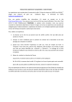
1.7 Adding the Temperature display
Select the StaticText Widget from the ToolBox on the left, go on the screen and draw a
big rectangle, covering the left-centre part of it.
Give it the name txtTemperature
Building a GUI with VGDD
Page 9 of 19
1.8 Creating a Big Font scheme
Go to the Scheme Control and click New.
Change the scheme's name to “BigFont” and then go to font selection by clicking on the
“...” button. This opens up the Font Chooser.
Click on the Add button, and choose a Gentium 72 points. The new font is added to the
sample list on the left.
To limit Flash font size, change the Charset property from RANGE (default) to
SELECTION.
We need all the numeric symbols from 0 to 9, the minus, the dot and the degree chars for
our temperature, so add to the CharsIncluded property the needed characters:
-.0123456789°
Then double-click on the font in the sample list on the left to select and assign it to the
newly created scheme.
Complete the scheme definition by setting the commonbgcolor property to white, the
same as the screen.
Set the txtTemperature text i.e. to “21.3°”, and change its Scheme property to “BigFont”.
Building a GUI with VGDD
Page 10 of 19
1.9 Defining Widget's Text as RAM buffer
The application needs to change the temperature text so this statictext's text shouldn't be
declared as CONST XCHAR[ ] but as a normal XCHAR[ ].
This
is
accomplished
by
changing
its
CdeclType
property
from
the
default
ConstXcharArray to RamXcharArray:
1.10 Adding a Picture
Drag and drop a Picture Widget and click on its Bitmap property. This opens up the
Resource Bitmap Chooser.
Click on the Add button and select the fan3.bmp bitmap. This adds the bitmap to the
available bitmaps set.
Then double click on the newly added bitmap to assign it to the Picture Widget, which will
be scaled up to fill the default picture size.
Resize the picture to suit your desired appearance style.
Change the name for the Picture to picFan.
Position the fan bitmap under the txtTemperature.
Building a GUI with VGDD
Page 11 of 19
1.11 Adding Buttons
Add two buttons, named TempUp and TempDown and create their respective schemes to
have them in different colours.
Finally add a StaticText label “Room Temperature” to obtain a final result like the following:
2 Running the GUI on the Development Board
2.1 Running the Wizard
Run the Wizard by clicking on the
button on the toolbar.
Go through each Wizard's step:
1-Set MPLAB X project. All data should be already correctly filled in by the plug-in and you
shouldn't have anything to modify:
Building a GUI with VGDD
Page 12 of 19
2-Select Hardware: select PIC24FJ256DA210 Development board and the 4.3” Powertip
display.
3-Set Options: be sure the “Graphics Objact Layer support” is checked (this enables
GOL support to use the Widgets).
The display driver needs a place where to store calibration data, so check “NVM: Use
SST25VF016 Flash chip” which is the one provided on the development board:
Building a GUI with VGDD
Page 13 of 19
4-Modify MPLAB X Project: simply click on “Modify Project” button. You can switch to
MPLAB X to see module files being added in real time by the VGDD-Link plug-in.
5-Finish: on the last tab, for your convenience, there's a last button to click: “Generate
Code”, which is completely equivalent to the one in the toolbar.
The Generate Code panel will be displayed:
Here you can revise the options, and finally click on “Generate Code”.
Again, a lot of modules will be added to the MPLAB X project through the VGDD-Link plugin, at least one for each Widget used in your project.
GOL needs a default font to be declared, so the first time you generate the code, a
warning will be displayed:
Building a GUI with VGDD
Page 14 of 19
2.2 Compiling the MPLAB X project and running it on the DevBoard
Switch to MPLAB X, and click on the Run Project
button.
The project should correctly compile and the connected board get flashed with the
firmware.
The screen you designed on PC will appear on the display.
You will notice that buttons are clickable but nothing happens. We have to add some
actions to them.
Let's modify the basic GUI we just created.
3 Modifying the GUI
3.1 Adding a Buttons Menu
Go back to VGDD, close the Wizard if you still haven't do so, and click on the
Screen button to add a second screen. Name it “Menu”
Add
Add a button, set its VertAlign property to bottom and its scheme to a new Scheme
named “Buttons”. Choose the desired colours for the button (face is color0).
Then copy&paste the button and
replicate it in order to obtain a threebuttons menu row. Center the buttons on
the screen.
Then select all three buttons by
surrounding them with the mouse and
duplicate the row with copy&paste.
Align the second row under the first one
to obtain the following result:
3.2 Adding button's bitmaps
One after the other, edit the Bitmap property of each button and add an icon (see step
1.10 on page 11).
Be sure to set each bitmap's
AllowScaling to false, otherwise they
will completely fill the buttons' faces.
When setting button's bitmap for the first
time with a bitmap whose AllowScaling is
set to false, the button itself get resized
to the bitmap's original size. For this
reason you'll have to manually resize the
button back to the desired dimensions.
Finally, change button's Texts to obtain a result like the one up above.
Building a GUI with VGDD
Page 15 of 19
3.3 Copying selected Widgets between screens
Go to the main screen and select upper
band, lower band and the date
StaticText
by clicking them while
holding the CTRL key. Then Copy them
with CTRL-C
Go back to Menu screen and paste the
three objects. Change the Date text to
“Menu” and shrink its width.
Add two arrow pictures on the bottom
band for navigation.
3.4 Duplicating a Screen
Select all Widgets on current Screen
with CTRL-A and copy them to clipboard
with CTRL-C.
Then add a new Screen to the Project,
name it “Menu2” and paste the Widgets
in it with CTRL-V.
Change the band title to “Menu 2” and
button Texts and Bitmaps with new
descriptions and icons.
Complete this sample GUI by replacing the lower band right arrow bitmap with a Home
one.
4 Designing GUI Navigation: Events Handling
Now that we have a Multi-Screen GUI we have to build the navigation logic between
Screens
4.1 Connecting Screens
Go on the Main Screen and select the Menu StaticText.
Click on the Event tab
.
This will display the Event Editor window.
Since you are going to make several event handling, it's convenient to pin it by clicking on
the
button in the upper right corner of the window.
Building a GUI with VGDD
Page 16 of 19
The only available event for the StaticText (GFX_GOL_STATICTEXT_ACTION) is already
selected in the Event dropdown.
In the Objects dropdown select the Menu (SCREEN) object.
In the Actions dropdown select the Go To Screen action.
Then click on Insert Code button. This will insert a
screenState=CREATE_MENU;
Repeat these steps on the Menu screen for both the left and right arrows in the bottom
band, to go back to Main screen and to go to Menu2 screen respectively.
Then go to Menu2 screen and repeat the same steps to go to Menu when the left arrow is
pressed and to go to Main screen when the Home icon is pressed.
4.2 Testing GUI navigation by Simulating it on the Player
Click on the Play Now
toolbar button
This will bring up the Player where you can verify by clicking on the GUI than screens are
displayed in the correct sequence.
Building a GUI with VGDD
Page 17 of 19
5 GUI development round-trip
5.1 Run modified GUI
At any moment during the development of the GUI you can click the Generate Code
toolbar button
.
In the Code Generation Window the “Don't Convert Graphics Resources” checkbox will be
checked only if you haven't done any addition/modification to the resources used in your
project. This will skip the GRC phase, reducing development time.
You can now switch to MPLAB X and Run the modified GUI on the hardware.
5.2 Hand-Writing Code
Let's add the code needed to read the DevBoard potentiometer and display it as
Temperature.
Switch to MPLAB X and open the VGDDmain.c source file. Near line 134 locate the
comment
// Application "background" code goes here
and insert the following code below it:
uint16_t potVal, OldPotVal;
uint32_t tickPot;
if (tick - tickPot > 259) {
tickPot = tick;
#if defined(ADC_POT)
potVal = TempOffset + (adcPot >> 1);
#else
potVal = TempOffset;
#endif
if (potVal != OldPotVal) {
OldPotVal = potVal;
Main_txtTemperature_Text[3] = potVal % 10 + 0x23;
potVal /= 10;
Main_txtTemperature_Text[1] = potVal % 10 + 0x23;
potVal /= 10;
Main_txtTemperature_Text[0] = potVal % 10 + 0x23;
potVal /= 10;
GFX_GOL_ObjectStateSet(GFX_GOL_ObjectFind(ID_Main_txtTemperature), GFX_GOL_STATICTEXT_DRAW_STATE);
if (OldPotVal > 200) {
GFX_GOL_ObjectStateClear(GFX_GOL_ObjectFind(ID_Main_picFan), GFX_GOL_PICTURECONTROL_HIDE_STATE);
} else {
GFX_GOL_ObjectStateSet(GFX_GOL_ObjectFind(ID_Main_picFan), GFX_GOL_PICTURECONTROL_HIDE_STATE);
}
GFX_GOL_ObjectStateSet(GFX_GOL_ObjectFind(ID_Main_picFan), GFX_GOL_PICTURECONTROL_DRAW_STATE);
}
}
Then go up and locate the
//
GLOBAL VARIABLES FOR APPLICATION
near line 93 and insert the following declaration:
uint8_t TempOffset = 0;
Last thing to do is to make the TempOffset variable visible to the VGDD events code:
Open the VGDDmain.h header file and at the bottom locate the
volatile extern SCREEN_STATES screenState;
and insert the following extern declarations below it:
extern uint8_t TempOffset;
extern volatile int16_t adcPot;
Building a GUI with VGDD
Page 18 of 19
Building and running the project now will display a simulated Temperature value which can
be modified via the potentiometer. Playing around the 20.0° threshold will turn on/off the
fan icon.
5.3 Using Events to change variable values
Go back to VGDD and, on the Main screen, select the Warmer button.
Open
the
Event
Editor,
in
the
Events
dropdown
select
GFX_GOL_BUTTON_ACTION_RELEASE event and add the following code:
the
TempOffset++;
Do the same with the Cooler button, but with the following line of code:
TempOffset--;
Now Generate Code as usual, switch to MPLAB X and run the project: the temperature
can now be adjusted both with the potentiometer (where applicable) and by touching the
two buttons, up and down by 0.1°.
6 End of Lab Exercise
Thank you!
Building a GUI with VGDD
Page 19 of 19