1
About the Documentation
Documentation Overview
This preface will familiarize the user with the ThermoFluor® 384 system documentation set
and explains how to use these documents.
Specifically, this preface includes the following sections:
Introduction to ThermoFluor® 384 System Documentation
Scope of these Documentis
Standard Conventions
Typographical Conventions
Special Terminology
The following table identifies the appropriate section to read in order to learn about specific
aspects of the documentation set.
To learn more about ...
Read the section....
Overview of the ThermoFluor® 384
System documentation
Introduction to ThermoFluor®
1-2
384 System Documentation
Scope of these Documents
Standard Conventions
1-2
Typographical Conventions
1-6
Special Terminology
1-7
Scope of these documents
Standard conventions
Typographical conventions
Special terminology
Copyright © 2001 3-Dimensional Pharmaceuticals, Inc.
Confidential
See page
1-6
0-1
May 2001
Artisan Scientific - Quality Instrumentation ... Guaranteed | (888) 88-SOURCE | www.artisan-scientific.com
Preface
ThermoFluor® Instrument Operations
Introduction to The rmoFIuor 384 System
Documentation
The ThermoFluor® 384 System Documentation is a set of documents covering all aspects of
the ThermoFluor® 384 system necessaiy to support executing applications Tins mformation
is organized into four separate documents
The first document, ThermoFluor® Instrument Operation" described above provides
basic information on how to install and use the ThermoFluor® 384 System.
ThermoFluor® Analysis Software," provides basic
The second document,
information on how to use the ThermoFluor® analysis software. This Software
provides a powerful way of analyzing the data generated by the ThermoFluor® 384
System.
The third document,
TheImoFluor® Applications," covers the
use of the
ThermoFluor® 384 instrument and Acquire version 3.0 analysis software for
applications in general.
The fourth document, ThermoFluor® Tutorials," is a series of tutorials to help a new
user learn how to perform common tasks. These tutorials are arranged in the order of
increasing complexity. They are covered in detail during ThermoFluor® training.
The Scope of these Documents
These documents are designed, with 3-Dimensional Pharmaceutical's training class, to
provide instructions and information needed to facilitate someone with background
knowledge in screening to use the ThermoFluor® 384 system. They should enable the user to
perform various tasks and develop an understanding of how the system works.
ThermoFluor® 384 System Instrument Operation
This document describes the basic construction and function of the ThermoFluor® 384
system. It also describes the installation, operation and maintenance of the ThermoFluor® 384
system. In addition it contains background information in the Appendix sections. You can
use this manual when you need information on how to operate the system or to train new
users of the system.
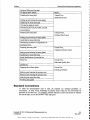
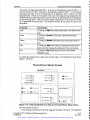
The following table outlines the information contained within the Instrument Operation
section of the documentation and which chapter to refer to for more information.
To learn more about ...
Read
ThermoFluor® 384 System
Chapter One, Introduction
Instrument specifications
Safety features
Overall system construction
Chapter Two,
Windowsm NT workstation (PC)
ThermoFluor® 384 instrument
Construction and Function
Plate processing system
Universal power supply
Copyright © 2001 3-Dimensional Pharmaceuticals, Inc.
Confidential
Artisan Scientific - Quality Instrumentation ... Guaranteed | (888) 88-SOURCE | www.artisan-scientific.com
0-2
May 2001
Preface
ThermoFluor® Instrument Operations
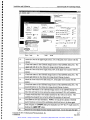
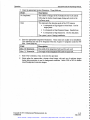
Continued from previous nage.
To learn more about
Read
Safety instructions
Chapter Three,
Installation and Calibration
Site preparation
System installation
Calibration of spots
Acceptance test
t
t
t
t
t
t
t
t
t
t
t
t
t
t
t
t
Safe operation
Chapter Four,
Operating software and controls
Total Control for Windows
Operation
TherrnoFluor® 384 Acquire 3.0
ThermoFluor® 384 System operation
System cleaning
Focusing the camera
Instrument Operation Chapter Five,
Maintenance
Adding/Changing filters
Replacing the light source
Troubleshooting
Repairs
Total Control for Windows Manual
Hudson Group, Plate Crane Manual
Appendix A
Consumables List
Appendix C
Appendix B
ThermoFluor® Analysis Software
This document describes how to analyze ThermoFluor® 384 system data using the
ThermoFluor® Analysis Software. It describes basic ThermoFluor theory, software navigation
and data analysis. It also describes the data exporting, batch processing of data, and DB sheet
data browsing. You can use this documentation when you need information on how to use
the ThermoFluor® Analysis Software or to train new users of the system.
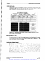
The following table outlines the information contained within the ThermoFluor® Analysis
Software section of the documentation and which chapter to refer to for more information.
To learn more about ...
Read
Introduction to the ThermoFluor® analysis
software
Chapter 1, Introduction
The ThermoFluor® analysis software interface
Chapter 2,
Getting Started
Starting the application
Opening an intensity file
Automated data analysis
Plate properties
Copyright © 2001 3-Dimensional Pharmaceuticals, Inc.
Confidential
Artisan Scientific - Quality Instrumentation ... Guaranteed | (888) 88-SOURCE | www.artisan-scientific.com
0-3
May 2001
Preface
ThermoFluor® Instrument Operations
Continued from previous page.
To learn more about ...
Read
ThermoFluor
Chapter 3,
Navigating Analysis Results
graphical user interface
Menu and toolbar options
Plate view
Bar chart view
Plot view
Layout table
Results table
Summary table
Averaging replicates
Modifying analysis settings
Chapter 4,
Customizing Analysis
Specifying reference wells
Excluding data points
Manual data analysis
Saving into a file
Chapter 5,
Output Options
Uploading into the database
Exporting into a text file
Printing
Copying views and tables
Batch analysis
Chapter 6,
Miscellaneous Options
Batch registration
Connect
Requery plate info
Edge detection
Appendix A
Dropout and Edge Detection
Dropout detection
ThermoFluor® Applications Guide
This document provides fundamental information for basic applications associated with the
ThermoFluor® 384 system. It describes the basics of protein preparation and high thru-put
screening (HTS). It also describes some general data analysis methods. You can use this
document when you need information on these applications with regard to the ThermoFluor®
384 system or to train new users of the system.
The following table outlines the information contained within the ThermoFluor® Applications
Guide of the documentation and which chapter to refer to for more information.
Copyright © 2001 3-Dimensional Pharmaceuticals, Inc.
Conf dential
Artisan Scientific - Quality Instrumentation ... Guaranteed | (888) 88-SOURCE | www.artisan-scientific.com
0-4
May 2001
Preface
ThermoFluor® Instrument Operations
To learn more about ...
Read
Overview of ThermoFluor® applications guide
Chapter 1,
Introduction
ThermoFluor® GLPs
Basic theory behind ThermoFluor®
Introduction to ThermoFluor® optimization
Chapter 2,
Optimizing ThermoFluor® Conditions
Condition optimization
Process optimization
Positive Controls
Secondary Confirmations
Introduction to ThermoFluor® High Throughput
Screening
Chapter 3,
High Throughput Screening
ThermoFluor High Throughput Screening
ThermoFluor® 384 assay setup
High Throughput Screening
Maintenance and Quality Assurance
Introduction to data analysis
Hit selection
Hit qualification
Hit re-testing
Chapter 4,
General Data Analysis
Secondary assays
ThermoFluor® Tutorials
This document provides procedures and exercises for common tasks associated with the
ThennoFluor® 384 system. It includes tutorials on protein characterization, sample
preparation and data collection. It also includes validation and optimization tutorials. You
can use this manual when you need information on these common tasks with regard to the
ThermoFluor® 384 system or to train new users of the system..
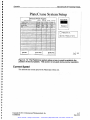
The following table identifies the common tasks described in the ThermoFluor® Tutorials of
the documentation and which Tutorial to refer to for practice in performing a given task.
To learn more about ...
Read
Preparing the assay plate
Tutorial One,
Initial Protein Screen
Setting up and running the assay plates
Analyzing the assay plate data
Viewing the analysis results
Determining the best concentration, mode, and
dye
Copyright © 2001 3-Dimensional Pharmaceuticals, Inc.
Confidential
Artisan Scientific - Quality Instrumentation ... Guaranteed | (888) 88-SOURCE | www.artisan-scientific.com
0-5
May 2001
Preface
ThermoFluor® Instrument Operations
Continued from previous page.
To learn more about ...
Read
Preparing the assay plate
Tutorial Two,
Buffer/Salt Screen
Setting up and running the assay plates
Analyzing the assay plate data
Viewing the analysis results
Determining the best pH, buffer, and salt
concentrations
Preparing the assay plate
Tutorial Three,
Uniform Plate Screen
Setting up and running the assay plates
Analyzing the assay plate data
Determining existence of irregularities or
systematic errors.
Preparing the assay plate
Tutorial Four,
Compound Library Screen
Setting up and running the assay plates
Analyzing the assay plate data
Initial identification of potential hits.
Select hits
Tutorial Five,
Select and Qualify Hits
Qualify hits
Preparing the uniform plates
Tutorial Six,
Screening Libraries
Setting up and running the accuracy test
Setting up and running the accuracy test
Analyzing the assay plate data
Verifying data quality
Standard Conventions
To make the documentation easy to read, the manuals use standard guidelines, or
conventions. In other words, formatting for specific items within the text will always be
presented in the same way. For example, software dialog box names are printed in Tahoma
font and all caps, such as the OUTPUT FILE dialog box.
Copyright © 2001 3-Dimensional Pharmaceuticals, Inc.
Confidential
Artisan Scientific - Quality Instrumentation ... Guaranteed | (888) 88-SOURCE | www.artisan-scientific.com
0-6
May 2001
Preface
ThermoFluor® Instrument Operations
Typographical Conventions
The documents use the following typographical conventions for the analysis and control
software applications.
Item
Depicted as:
For example:
Menu name
Toolbar name
Menu command
The FILE menu
The PAGER toolbar
The Open file command
Toolbar buttons
Dialog box name
Tahoma font, all caps, bold
Tahoma font, all caps, bold
Tahoma font, initial cap, bold
Tahoma font, initial cap, bold
Tahoma font, all caps
Dialog box field name
Text entry
Keyboard keys
Tahoma font, initial cap
Courier (PCL6) font
Tahoma font, initial cap en-
closed in <>
The Selection button
Type the desired file name in the
PRINT dialog box
Number Of Copies
Enter the file name Batch. mt
Press and hold the <CtrI> and
<Shift> keys
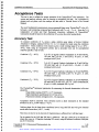
Special Terminology
The following table provides definitions for some of the terms used in conjunction with
ThermoFluor®.
Term
Definition
Hit
A well on a screening plate that exhibits a signal strength that
exceeds the Tm shift threshold set as a significant response for
the run.
*jnt(JNT filee
File created by the ThermoFluor® Acquire 3.0 application which
contains integrated intensity values for wells in a plate.
File that contains raw camera exposure data. The ThermoFluor®
*.psqtpsQ file
*tf/TF file
Acquire 3.0 application creates *.int integration files from the
*.psq files that correspond to the replicate exposures for a well.
The ThermoFluor® Analysis Software creates this file. It
contains the fitted data along with other values that are calculated
and/or downloaded from a data base for each well on a plate.
The table below lists common acronyms that are used in conjunction with ThermoFluor®.
Acronym
Definition
TCW
Total Control for Windows program developed by Hudson
Control Group
Copyright © 2001 3-Dimensional Pharmaceuticals, Inc.
Confidential
0-7
May 2001
Artisan Scientific - Quality Instrumentation ... Guaranteed | (888) 88-SOURCE | www.artisan-scientific.com
Preface
ThennoFluor® Instrument Operations
Copyright © 2001 3-Dimensional Pharmaceuticals, Inc.
Confidential
Artisan Scientific - Quality Instrumentation ... Guaranteed | (888) 88-SOURCE | www.artisan-scientific.com
0-8
May 2001
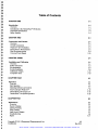
Table of Contents
CHAPTER ONE
1-1
Introduction
1-1
Overview
Introduction to the ThermoFluor® 384 System
Instrument Specifications
Safety Features
1-1
1-2
1-4
1-5
CHAPTER TWO
2-1
Construction and Function
2-1
2-1
2-2
2-3
2-4
2-9
2-12
Overview
Overall Construction
Windows NT Workstation
ThermoFluor® 384 Instrument
Plate Processing System
Universal Power Supply
CHAPTER THREE
3-1
Installation and Calibration
3-1
3-1
3-2
3-3
3-8
3-15
3-19
Overview
Safety instructions
Site preparation
System installation
Calibration of Spots
Acceptance Tests
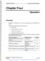
CHAPTER FOUR
4-1
Operation
4-1
4-1
4-2
4-3
Overview
Safe Operation
Operating Software and Controls
Total Control for Windows1M
ThermoFluor® 384 Acquire 3.0
4-10
4-18
4-29
ThermoFluor® 384 System Operation
CHAPTER FIVE
5-1
Maintenance
s-1
Overview
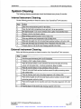
System Cleaning
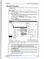
Camera Focusing
Filter Changes
Light Source Changes
Troubleshooting
Repair
Copyright © 2001 3-Dimensional Pharmaceuticals, Inc.
Confidential
5-1
5-2
5-3
5-5
5-7
5-8
5-17
0-9
May 2001
Artisan Scientific - Quality Instrumentation ... Guaranteed | (888) 88-SOURCE | www.artisan-scientific.com
Copyright © 2001 3-Dimensional Pharmaceuticals, Inc.
Confidential
Artisan Scientific - Quality Instrumentation ... Guaranteed | (888) 88-SOURCE | www.artisan-scientific.com
Chapter One
Introduction
Overview
This chapter will familiarize the user with the ThennoFluor® 384 system and its safety
features.
Specifically, this chapter includes the following sections:
Introduction to the ThermoFluor®384 System
Instrument Spec,fìcations
Safety Features
The following table identifies the appropriate section to read in order to learn how to perform
a specific task.
To learn more about ...
Read the section....
ThermoFluor® 384 system
Introduction to
ThermoFluor® 384 System
Instrument Specifications
Safety Features
Instrument specifications
Safety Features
Copyright © 2001 3-Dimensional Pharmaceuticals, Inc.
Confidential
See page
1-2
l-4
1-5
l-1
May2001
Artisan Scientific - Quality Instrumentation ... Guaranteed | (888) 88-SOURCE | www.artisan-scientific.com
I
4
Introduction
TheimoFlour® 384 Operating Manual
Introduction to the ThermoFIuor 384 System
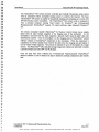
The ThermoFluor® 384 system performs miniaturized fluorescence based thermal shift assays
for the high throughput screening of compound libraries. The ThermoFluor® screening
strategy has several advantages over the more conventional HTS methodologies, the most
important of which is that it relies on a general physical process common to most, if not all,
drug targets - thermal unfolding of biomolecules and their ligand bound complexes. The
ThermoFluor® instrument measures dye fluorescence in the presence of a protein. As the
protein unfolds its hydrophobic parts are exposed which creates an environment that causes
the dye to fluoresce.
The more the protein unfolds the greater the intensity of the
fluorescence.
Figure 1- 1: The thermal unfolding of the protein allows the dye to enter a
more hydrophobic environment and fluoresce.
In this manner the protein's melting transition can be measured. More importantly for the
ThermoFluor® screening strategy the effects of ligand binding on the protein's melting
transitions can be measured. See the Application Manual for more details on the theoiy
behind ThermoFluor®.
Figure 1-2: Ligand binding shifts the unfolding temperature of the protein.
Copyright © 2001 3-Dimensional Pharmaceuticals, Inc.
Confidential
Artisan Scientific - Quality Instrumentation ... Guaranteed | (888) 88-SOURCE | www.artisan-scientific.com
1-2
May 2001
Introduction
ThermoFlour® 384 Operating Manual
The ThermoFluor® 384 system provides a flexible and modular fluorescence assay system
with an automated robotic microplate loading system to perform this function. The basic
ThermoFluor® 384 system is capable of sequentially loading and unloading up to twenty (20)
384-well thermal cycler microplates. The ThermoFluor® 384 system works in conjunction
with a personal computer running Total Control for WindowsTM and 3-Dimensional
Phannaceuticals' ThermoFluor® Acquire 3.0 côntrol software under MicrosOft WindôwslM
NT.
The robotic microplate handler (PlateCraneTM by Hudson Control Group) moves sample
plates from an input storage magazine to the imaging area of the instrument.
As the
microplate is removed from the input magazine a barcode reader reads the plate's bar code
identification number. Once the microplate is in the imaging area the ThermoFluor® control
software initiates a ThermoFluor® experiment on the microplate. When the experiment is
completed, the robotic handler then retrieves the plate from the imaging area and places it
into an output storage magazine. This process is repeated for up to 20 microplates in a single
session. The PlateCraneTM robot and plate storage magazines (stacks) are optimized to handle
a specified brand and model 384 well PCR plates.
Once the data have been collected the 3-Dimensional Phannaceuticals' ThermoFluor®
analysis software is used to analyze the data to determine melting temperatures and identify
hits.
Copyright © 2001 3-Dimensional Pharmaceuticals, Inc.
Confidential
Artisan Scientific - Quality Instrumentation ... Guaranteed | (888) 88-SOURCE | www.artisan-scientific.com
l-3
May 2001
Introduction
ThermoFlour® 384 Operating Manual
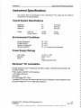
Instrument Specifications
This section gives the specifications of the ThermoFluor® 384 system and the conditions
necessaiy for it to function properly
Overall System Specifications
Height (H):
Width (W):
Depth (D)
Table Top
Control Cabinet
Weight:
Environmental Conditions
Storage Temperature
Storage Humidity:
Operation Temperature:
Operation Humidity:
200 - 40° C
20-80%
20°24° C
30 - 50 % relative (non-condensing)
Power Supply Ratings
Line Voltage
Frequency
Power
110 VAC +1-10%
60 Hz +1-10%
iSA
Properly grounded outlet
Windows
NT workstation
Hewlett-Packard VectraTM Pentium ifi, 300 METz or better, 128 MB RAM, hard disk with
10.0 GB or better
SVGA monitor with 800 x 600 resolution
3 1/2" floppy disk drive
CD-ROM
250 MB Iomega ZIPTM Drive
2 available PCI slot (one for camera card and one for RocketportTM serial expansion card)
Microsòft Windows NT 4.0 with Service Pack 6.0
Copyright © 2001 3-Dimensional Pharmaceuticals, Inc.
Confidential
Artisan Scientific - Quality Instrumentation ... Guaranteed | (888) 88-SOURCE | www.artisan-scientific.com
1-4
May 2001
Introduction
ThermoFlour® 384 Operating Manual
Safety Features
The ThermoFluor® 384 system should be setup and run by 3-Dimensional Pharmaceuticals
Inc. factory trained personnel only. If you are not factory trained, immediately contact 3Dimensional Pharmaceuticals, Inc. by e-mail at en gsupport@3 dp. corn to schedule training.
This Operating Manual contains information and procedures for the safe installation and
operation of the ThermoFluor® 384 system. Before installing or running the ThernioFluor®
384 system, completely and thoroughly review the latest version of this document. If any
instructions are unclear or unfamiliar to you, immediately contact 3-Dimensional
Pharmaceuticals, Inc. by e-mail at engsupport3dp.corn for clarification and proper
operation.
Abnormal instrument operation should be immediately noted and instrument use discontinued
until examined by a representative from 3-Dimensional Pharmaceuticals, Inc.
As with all laboratory equipment, follow all standard operating procedures and policies. An
operations and maintenance logbook should be maintained at the instrument's location.
Handle with Care
To avoid equipment damage handle components carefully. Handle the CCD Camera with
particular care, as it is fragile.
Uft Properly
Use proper lifting techniques when lifting shipping containers and system components. Four
(4) persons, positioned at each corner, should be used when lifting the system stand and the
instrument base plate.
Electrical
Ensure the system's universal power supply is unplugged and that all power switches are in
the "OFF" position before performing maintenance.
Use an ESD (electrostatic discharge) wrist grounding strap and discharge cable per
manufacturer' s instructions during all signal cable connections to avoid damage to the
equipment by static electricity.
UV light
Avoid looking directly into UV light source as it may cause damage to the eye.
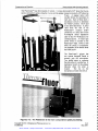
Labeling
Warning labels are located on the instrument to avoid potential dangerous situations to an
operator or other lab personnel using the ThermoFluor® 384 instrument. Normal operational
labels are provided to clarif' function of the various indicator lights, switches and electrical
connections used in normal operations. Each label, its location, and a brief description of the
instrument operation associated with the label are listed below.
Copyright © 2001 3-Dimensional Pharmaceuticals, Inc.
Confidential
Artisan Scientific - Quality Instrumentation ... Guaranteed | (888) 88-SOURCE | www.artisan-scientific.com
l-5
May 2001
4
4
Introduction
ThermoFlour® 384 Operating Manual
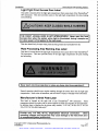
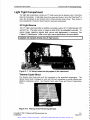
Light Tight Front Access Door Label
4
4
This label is located above the light tight compartment front access door of the ThermoFluor®
384 instrument. This door provides access to the light tight compartment for plate loading
and unloading.
4
!4
4
4
I, I
CAUTION!!! KEEP CLOSED WHILE RUNNING
I
4
4
4
4
THE FRONT ACCESS DOOR IS NOT INTERLOCKED!!! Never open the front
access door when the system active light is illuminated, during a sample run
I or when power is first applied to the instrument.
I
This door should only be open when plates are being loaded and unloaded from the
Plate Processing Area Warning Area Label
This label is located above the light tight compartment front access door of the ThermoFluor®
384 instrument. This door provides access to the light tight compartment for plate loading
and unloading.
I
I
I
I
I
4
I
I
a
a
i
Never reach into the access door or place any items into the access door!!!
Normal operation should never require reaching through the access door into the light tight
compartment. Such action is hazardous, and can result in injury or damage to the instrument.
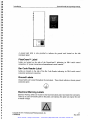
Manufacturer's Serial Plate Label
This label in located on the right side of the ThermoFluor® 384 instrument.
These
connections should be made with no power applied to either the computer or the instrument.
In addition there is labeling for the power entry module, "110 yAC, 60 Hz ONLY" &TUse
lOA, 250 VAC Slo-Blo Fuses only!!"
I Provide only 110 yAC, 60 Hz, single-phase electrical connection.
Othefl
operating voltages and frequencies may cause damage to the instrument and I
or unexpected system performance.
Copyright © 2001 3-Dimensional Pharmaceuticals, Inc.
Confidential
Artisan Scientific - Quality Instrumentation ... Guaranteed | (888) 88-SOURCE | www.artisan-scientific.com
1-6
May 2001
a
a
a
a
a
a
a
a
a
a
a
a
a
a
a
a
a
a
a
a
a
a
Introduction
ThermoFlour® 384 Operating Manual
L
I
L
L
°
A ground stud label is also provided to indicate the ground stud located on the side
instrument panel.
PlateCraneTM Label
Labels are located on the side of the PowerCraneTM indicating its DB-9 serial control
connection, AC power connection and manufacturerts serial number."
Bar Code Reader Label
Labels are located on the side of the Bar Code Reader indicating its DB-9 serial control
connection and power connection.
Ground Labels
Ground labels are located throughout the instrument. These labels indicate a chassis ground
connection point.
Electrical Warning Labels
Electrical warning labels are located on the back instrument panel and inside the instrument.
There are no user serviceable parts in this panel, and opening this panel can expose the user
to unsafe voltages.
Copyright © 2001 3-Dimensional Pharmaceuticals, Inc.
Confidential
1-7
May 2001
Artisan Scientific - Quality Instrumentation ... Guaranteed | (888) 88-SOURCE | www.artisan-scientific.com
Introduction
ThermoFlour® 384 Operating Manual
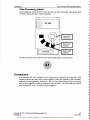
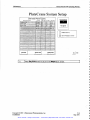
Plate Processing Labels
Several additional labels are best viewed from the top of the instrument. Specifically, plate
orientation labels and input I output stack labels.
P1ateCrane'
robotic arm
Stack i input
magazine
Stack2 output
magazine
The plate orientation label locates well Al on each plate placed in the instrument:
Al
Connections
The ThermoFluor® 384 instrument CCD camera SCSI connection and controller serial
connection should be made with no power applied to either the computer or the instrument.
Similarly the plate processing PlateCraneTM and bar code reader cables should be connected
with no power applied to either the computer or the instrument. The UPS inside the workcell
must be turned off, even if no external power is applied.
Copyright © 2001 3-Dimensional Pharmaceuticals, Inc.
Confidential
Artisan Scientific - Quality Instrumentation ... Guaranteed | (888) 88-SOURCE | www.artisan-scientific.com
l-8
May2001
p
p
p
p
p
I
p
p
Introduction
ThermoFlour® 384 Operating Manual
Chapter Two
s
s
s
s
Construction and Function
p
s
p
p
p
p
p
p
p
Overview
This chapter will familiarize the user with the construction of the ThermoFluor® 384 system
and the function of its major components.
Specifically this chapter will include the following sections:
Overall system construction
Windows
NT workstation (PC)
Therm oFluor® 384 instrument construction
Plate processing system construction
The following table identifies the appropriate section to read in order to learn more about the
construction of the ThermoFluor® 384 system.
To learn more about
Read the section....
Overall system construction
Overall Construction
Windows NT workstation (PC)
WindowsNT Workstation
ThermoFluor® 384 instrument construction
ThermoFluor®384
Instrument
Plate processing system construction
Plate Processing System
See page
Copyright © 2001 3-Dimensional Pharmaceuticals, Inc.
Confidential
Artisan Scientific - Quality Instrumentation ... Guaranteed | (888) 88-SOURCE | www.artisan-scientific.com
2-2
2-3
2-4
2-9
2-1
May 2001
4
4
Construction and Function
ThermoFlour® 384 Operating Manual
4
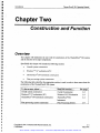
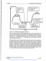
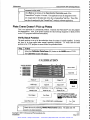
Overall Construction
The ThermoFluor® 384 system is a flexible and modular fluorescence assay system with an
automated plate processing system The basic ThermoFluor® 384 system is capable of
sequentially loading and unloading up to twenty (20) 384-well thermal cycler microplates.
The ThermoFluor® 384 instrument works in conjunction with a WindowsTM NT workstation
running 3-Dimensional Phannaceuticalst ThermoFluor® Acquire 3.0 control software to
perform the fluorescence assay The plate processing system has a PlateCraneTM robotic arm
that moves sample plates from an input storage magazine to the imaging area of the
instrument, after which the ThermoFluor® Acquire 3.0 control software program initiates a
ThermoFluor® experiment on the microplate. When the experiment is completed, the Plate
Crane retrieves the plate from the imaging area and places it into an output magazine. The
various components or the system are powered by a universal power supply.
4
4
4
4
I
4
4
4
4
4
4
7
4
4
4
Plate
Processing
System
ThermoFluor® 384
Instrument
4
4
4
4
4
4
4
4
4
4
4
4
I
WindowsTM NT
Workstation
4
4
Universal Power
Supply
I
4
4
4
4
Figure 2-1: The ThermoFluor® 384 system.
I
Copyright © 2001 3-Dimensional Pharmaceuticals, Inc.
Confidential
Artisan Scientific - Quality Instrumentation ... Guaranteed | (888) 88-SOURCE | www.artisan-scientific.com
2-2
May 2001
4
I
Construction and Function
ThermoFlour® 384 Operating Manual
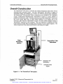
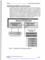
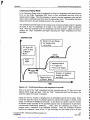
WindowsTM NT Workstation
The WindowsTM NT Workstation contains the software that controls the operation of the
system and creates data files that are analyzed by the ThermoFluor® analysis software. The
ThermoFluor® analysis software is usually installed on a separate analysis workstation. The
ThermoFluor® analysis software will be discussed in the ThermoFluor® Analysis Software
Manual. Total Control for WindowsTM (TCW) operates the overall system and allows the
running of multiple plates. It directly operates the plate processing system and it indirectly
operates the ThermoFluor® 384 instrument through the ThermoFluor® Acquire 3.0 control
software. The ThermoFluor® Acquire 3.0 control software interfaces with a CCD camera and
an embedded controller in the ThermoFluor® 384 instrument. The ThermoFluor® Acquire
3.0 control software can be used to run a single plate without the use of TCW or the
PlateCraneTM robotic arm. The software relationships are illustrated below.
Analysis
WindowsNT Workstation
Total Control for
WindowsTM
ThermoFluor®
Acquire 3.0
Workstation
ThermoFluor®
Analysis Software
J
PlateCrane
Bar Code
Reader
CCD Camera
I
-1mbedded Controller
Plate Processäna System
ThermoFluor®384 Instrument
Figure 2-2: WindowsTM NT Workstation software applications.
Total Control for WindowsTM
This software controls the PlateCraneTM robotic ann movements and interfaces with the bar
code reader. The method that is used to move the microplates from the input storage
magazine to the imaging area then to the output magazine is programmed using this
application. The program also interacts with the ThermoFluor® Acquire 3.0 control software
to coordinate actions between the ThermoFluor® 384 instrument and the Plate Processing
system. Refer to Appendix A for details.
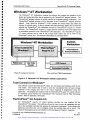
ThermoFluor® 384 Acquire 3.0
The ThennoFluor® Acquire 3.0 control sothvare provides the user interface for the
ThermoFluor® 384 system. This software allows the user to enter run parameters that are
sent to the embedded controller that operates the instrument components. It also initiates the
experiment and allows the user to designate where the resulting data will be saved. The
details of this program and its user interface will be discussed in Chapter 4, Operation.
Copyright © 2001 3-Dimensional Pharmaceuticals, Inc.
Confidential
2-3
May 2001
Artisan Scientific - Quality Instrumentation ... Guaranteed | (888) 88-SOURCE | www.artisan-scientific.com
Construction and Function
ThennoFlour® 384 Operating Manual
The rmoFIuor 384 Instrument
The ThermoFluor® 384 Instrument actually performs the fluorescence assays. It consists of
three compartments. These are the:
Optical compartment
Light tight compartment
Power and control
compartment
Optical Compartment
The optical compartment contains the
optical components that measure the
fluorescence. These include the CCD camera,
lens and filter wheel. This compartment is
accessible by the user in order to change filters.
Figure 2-3: Back of ThermoFluor® 384
Instrument.
CCD Camera
The CCD camera records the plate fluorescence images. It is a Roper Scientific camera
model Sensys 0400. It has a half-inch mega pixel format. The CCD camera comes with its
own power supply that is located in the optical compartment and plugged into the system
Universal power supply. Refer to the Photometric's SenSys User Manual, Advanced Camera
Operation Manual and Software Guide Manual for more details.
Figure 2-4: CCD camera mounted in instrument.
CAUTION: The camera should never be connected or removed from a live
power cable. This could damage the camera's electronic components. Verify
the camera's power supply is switched OFF and unplugged from the Universal
Power Supply before disconnecting its power cable.
Copyright © 2001 3-Dimensional Phanriaceuticals, Inc.
Confidential
Artisan Scientific - Quality Instrumentation ... Guaranteed | (888) 88-SOURCE | www.artisan-scientific.com
2-4
May 2001
Construction and Function
ThermoFlour® 384 Operating Manual
Lens
The Lens focuses the image in the camera. It is a 25 mm F 0.95 C-mount lens with
aperture and focus adjustment. The aperture adjustment should always be set to
wide open. The focus adjustment will be discussed in Chapter 3, Installation and
Calibration and Chapter 5, Maintenance.
Figure 2-5: 25 mm lens for CCD camera.
Filter Wheel
The filter wheel allows for various optical filters to be used in the instrument to
provide the capability of measuring images from more specific regions of the Uy
spectrum The filter wheel can hold 4 filters The ThermoFluor® 384 instrument is
supplied with a standard ThermoFluor filter in position i Oriel 50 mm by 4 mm
filters are recommended. The embedded controller discussed below controls the
positioning of the filter wheel.
Figure 2-6: Filter wheel in position 1.
Copyright © 2001 3-Dimensional Pharmaceuticals, Inc.
Confidential
Artisan Scientific - Quality Instrumentation ... Guaranteed | (888) 88-SOURCE | www.artisan-scientific.com
2-5
May 2001
Construction and Function
ThermoFlour® 384 Operating Manual
4
4
Light Tight Compartment
4
The light tight compartment contains an LTV light source and the thermal cycler' s block that
heats the microplates. A light tight access door opens and closes to allow thé PlateCraneTM to
place the microplates on the Thermal cycler' s block and then remove them, Rear access to
this compartment is limited to those trained in instrument maintenance.
4
UVLîghtSource
4
The UY light source provides a uniform, consistent source of UY light between 350
and 410 nm. The light source is turned on and off by the embedded controller. To
ensure proper operation regular bulb service and replacement is necessary. See
Chapter 5, Maintenance. Refer to the light source specifications for more details.
4
I
4
4
4
4
I
I
I
I
I
Caution! Do not look directly into UV light source.
4
4
I
4
4
4
4
4
Figure 2- 7: UV lamps viewed as they appear in the instrument.
4
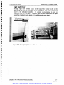
Thermal Cycler Block
4
The thermal cycler heats and cools the microplates to the prescribed temperatures. The
thermal cycler block is designed to work with 384 well microplates to provide efficient and
effective temperature control. See Thermal Cycler under Power and Control Compartment
below.
I
I
I
I
I
4
I
I
I
4
4
I
4
Figure 2-8: The top of the Thermal Cycler blok.
Copyright © 2001 3-Dimensional Pharmaceuticals, Inc.
Confidential
Artisan Scientific - Quality Instrumentation ... Guaranteed | (888) 88-SOURCE | www.artisan-scientific.com
2-6
May 2001
4
4
4
4
Construction and Function
ThermoFlour® 384 Operating Manual
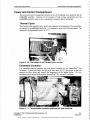
Light Tight Door
The light tight door provides access to the top of the thermal cycler so the
PlateCraneTM can place the microplates on the heater block. The door is opened and
closed by the embedded controller.
Its opening is programmed to work in
conjunction with the PlateCraneTM. Caution!! Do not place hand(s) into the open
door when running in batch mode as it could close and cause injury.
Figure 2-9: The light tight door and it's drive motor.
Copyright © 2001 3-Dimensional Pharmaceuticals, Inc.
Confidential
Artisan Scientific - Quality Instrumentation ... Guaranteed | (888) 88-SOURCE | www.artisan-scientific.com
2-7
May 2001
ThermoFlour® 384 Operating Manual
Construction and Function
Power and Control Compartment
The power and control compartment contains the rest of the thermal cycler assembly and the
embedded controller.
Because of the presence of high voltage components and the
embedded controller, access to this compartment is limited to factory technicians.
Thermal Cycler
The thermal cycler assembly raises, lowers and maintains the temperature of the microplates
as directed by the embedded controller. It is designed to work with a 384 microplate. The
temperature is programmable from 4 to 99° C.
ç)
lilt
.-
Ffl
Figure 2- 10: The bottom of the Thermal Cycler and fan.
Embedded Controller
The embedded controller performs real time control functions for the ThermoFluor® 384
Instrument. It opens and closes the light tight door, turns the UY light source on and off,
operates the filter wheel, and controls the temperature of the thermal cycler. The user
interfaces with the controller through the ThermoFluor® 384 Acquire 3.0 software.
Figure 2- 11: The embedded controller performs real time functions.
Copyright © 2001 3-Dimensional Pharmaceuticals, Inc.
Confidential
Artisan Scientific - Quality Instrumentation ... Guaranteed | (888) 88-SOURCE | www.artisan-scientific.com
2-8
May 2001
R
R
R
I
,
Construction and Function
ThemioFlour® 384 Operating Manual
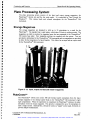
Plate Processing System
The plate processing system consists of the input and output storage magazines, the
PlateCraneTM robotic arm and the bar code reader. It is controlled by Total Control for
WindowsTM.
This system loads and unloads microplates for the ThermoFluor® 384
instrument.
R
R
R
R
R
R
Storage Magazines
The storage magazines are designed to hold up to 30 microplates in a stack for the
PlateCraneTM. The standard run is eight plates, which takes 24 hours in up/down mode. The
magazines are held in position by magazine bases that are connected to the ThermoFluor®
384 system base plate. Four magazine positions are supplied with the system. Two are
provided to hold plates for the ThermoFluor® 384 instrument and two magazines are provided
to allow for the integration of a liquid handler. This allows for an input and an output stack
for the TherinoFluor® 384 instrument.
R
R
1
g
Figure 2- 12: Input, output and barcode reader magazines.
PlateCraneTM
The PlateCraneîM robotic arm moves 384-well thermal cycler microplates from the input
storage magazine to the thermal cycler block in the ThermoFluor® 384 instrument's light
tight compartment. When the experiment is completed, the PlateCraneTM retrieves the plate
and places it into the output magazine. This process is repeated for up to 30 microplates in
each a single session. Alternatively, a lid can be used as a "topper' on the stack, if desired, to
prevent sample contamination.
Copyright © 2001 3-Dimensional Pharmaceuticals, Inc.
Confidential
Artisan Scientific - Quality Instrumentation ... Guaranteed | (888) 88-SOURCE | www.artisan-scientific.com
2-9
May 2001
Construction and Function
ThennoFlour® 384 Operating Manual
The PlateCraneTM has three degrees of motion. It rotates horizontally 3450 about the R-axis,
moves verticallyl 9 inches along the Z-axis and the gripper rotates horizontally 350°about the
P-axis. A stepper motor with
encoder drives the movement in
each axis. Bach of these have a
mechanical switch to determine
the "Home" position. The R and
Z-axis have hard stops. A serial
cable from the rear of the
PlateCraneTM connects (DB-9
connector) to a serial port on the
Rocketport serial expansion
card of the NT Workstation for
communications. A rocker type
power switch is located on the
PlateCraneTM base. Power is ON
when the switch is illuminated.
See Appendix B for details about
the PlateCraneTM.
The PlateCraneTM gripper has
two custom designed hands to
securely grip the microplates.
Two guides assist in centering
the plate when it is picked up. A
mechanical switch in the gripper
indicates when the plate is
located.
The lip on the
microplate activates this switch.
Figure 2- 13: The PlateCrane is the main component in plate processing.
Copyright © 2001 3-Dimensional Pharmaceuticals, Inc.
Confidential
Artisan Scientific - Quality Instrumentation ... Guaranteed | (888) 88-SOURCE | www.artisan-scientific.com
2-10
May 2001
Construction and Function
ThermoFlour® 384 Operating Manual
Bar Code Reader
This is a standard Keyence BL 185 programmable bar code reader that reads 2 of 5
interleave. Each microplate has a bar code placed on it that identifies it to the system.
Figure 2- 14: 384 well microplate with barcode gabeL
This helps to ensure proper correspondence of plates to data. The barcode reader
communicates with the NT Workstation though a serial cable connected to the control
computer's Rockport expansion card
Figure 2- 15: Barcode reader records plate identification numbers.
Copyright © 2001 3-Dimensional Pharmaceuticals, Inc.
Confidential
Artisan Scientific - Quality Instrumentation ... Guaranteed | (888) 88-SOURCE | www.artisan-scientific.com
2-11
May 2001
Construction and Function
ThermoFlour® 384 Operating Manual
Universal Power Supply
An APC Smart UPS universal power supply is used to provide stable uninterrupted power to
the system. All system components should be plugged into this power supply to ensure
proper operation. The power supply is then plugged into a standard 110-120 VAC outlet.
The UPS is sized to provide 10 to 15 minutes of operating time. For continuous
uninterrupted operation an emergency backup power source should be supplied. Refer to the
APC Smart UPS Manual for additional details.
14
4
4
4
4
4
4
4
4
4
4
4
4
4
4
I
4
4
4
Universal Power
Supply
I
I
WindowsTM NT
Workstation
Figure 2- 16: Cabinet containing the universal power supply and WindowsTM
NT Workstation.
Copyright © 2001 3-Dimensional Pharmaceuticals, Inc.
Confidential
Artisan Scientific - Quality Instrumentation ... Guaranteed | (888) 88-SOURCE | www.artisan-scientific.com
2-12
May 2001
4
4
4
I
I
I
I
I
I
4
4
I
I
Construction and Function
ThermoFlour® 384 Operating Manual
Chapter Three
Installation and Calibration
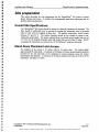
Overview
This chapter provides information and instructions for installing and calibrating the
ThermoFluor® 384 system. It also describes how to perform an acceptance test for the
system.
Specifically, this chapter includes the following sections:
Safety instructions
Site preparation
System installation
Calibration of spots
Acceptance test
The following table identifies the appropriate section to read in order to learn more about a
specific item.
To learn more about ...
Read the section....
Safety instructions during installation.
Safety instructions
3- 5
Preparing a site for the system.
Site preparation
System installation
3- 3
Calibration of spots
Acceptance test
3- 15
Installing the system
Calibrating the instrument.
Performing an acceptance test for the system
Copyright © 2001 3-Dimensional Pharmaceuticals, Inc.
Confidential
See page
3- 8
3- 19
3-1
May 2001
Artisan Scientific - Quality Instrumentation ... Guaranteed | (888) 88-SOURCE | www.artisan-scientific.com
Installation and Calibration
ThermoFlour® 384 Operating Manual
Safety instructions
The ThermoFluor® 384 system should be set up and run by 3-Dimensional Pharmaceuticals
Inc. factory trained personnel only. If you are not factory trained, immediately contact 3Dimensional Phannaceuticals, Inc. at 1-610-458-8959 to schedule training
This Operating Manual contains mformation and procedures for the safe installation and
operation of the ThermoFluor® 384 system. Before installing or running the ThermoFluor®
384 system, completely and thoroughly review the latest version of the Operating Manual. If
any instructions are unclear or unfamiliar to you, immediately contact 3-Dimensional
Pharmaceuticals, Inc. at l-610-458-8959 for clarification and proper operation.
Please locate and identify all safety and informational labels on the instrument. If any labels
are missing, smudged or damaged (see Chapter 1, Introduction) discontinue use and contact
3-Dimensional Pharmaceuticals, Inc. for replacements.
Please locate, identify and recognize all safety items on the instrument including covers and
panels. If any items are missing, damaged or disabled in any way, discontinue use and
contact 3-Dimensional Pharmaceuticals, Inc. for instrument repair.
Handle with Care
To avoid equipment damage handle components carefully. Handle the CCD Camera with
particular care, as it is fragile.
Lift Properly
Use proper lifting techniques when lifting shipping containers and system components. Four
(4) persons, positioned at each comer, should be used when lifting the system stand and the
instrument base plate.
Electrical
Do not plug the universal power supply in until the installation procedure specifically
instructs you to plug in the universal power supply. Then before plugging in the universal
power supply verify that all power switches are in the "OFF" position. Verify that the wall
outlet for the universal supply is 110 yAC, 60 Hz and properly grounded. Use a ESD
(electrostatic discharge) wrist grounding strap and discharge cable per the manufacturer' s
instructions during all signal cable connections to avoid damage to the equipment by static
electricity.
Copyright © 2001 3-Dimensional Pharmaceuticals, Inc.
Confidential
Artisan Scientific - Quality Instrumentation ... Guaranteed | (888) 88-SOURCE | www.artisan-scientific.com
3-2
May 2001
R
a
p
a
i
I
a
a
Installation and Calibration
ThermoFlour® 384 Operating Manual
Site preparation
This section descnbes the site requirements for the ThermoFluor® 384 system to ensure
proper function and access. It includes the recommended stand-alone placement and the
alternate bench top placement
Overall Site Specifications
a
a
a
a
The ThermoFluor® 384 system should be located in a clean dry laboratory environment. The
floor should be sufficiently level to provide for leveling the instrument front to back and
sided to side with the supplied leveling feet. The ambient temperature should remain
between 20° and 24° C. The relative humidity should be low enough to ensure a noncondensing environment. The system operates from a universal power supply that runs on
110 yAC, 60 Hz properly grounded outlet and should draw no more than 15 amps. The PC
is equipped for connection to a network via a 10/loo EthernetTM connector if desired.
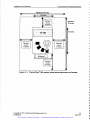
Stand Alone Placement and Access
The footprint of the system is 24 inches wide by 36 inches deep.
The system stands
approximately 66 inches high A minimum of 18 mches (24 inches recommended) should be
a
a
provided on the side and back of the instrument to ensure adequate access for routine
maintenance and operation. A minimum of 36 inches should be provided at the front of the
instrument. See figure 3.1 below.
a
a
a
a
a
a
a
a
a
a
a
a
a
a
Copyright © 2001 3-Dimensional Pharmaceuticals, Inc.
Confidential
Artisan Scientific - Quality Instrumentation ... Guaranteed | (888) 88-SOURCE | www.artisan-scientific.com
3-3
May2001
Installation and Calibration
ThermoFlour® 384 Operating Manual
Minimum 60 inches
24 inches
A
Minimum
Minimum
Access
90 inches
18 inches
A
36 inches
TF384
Minimum
Access
18 inches
Minimum
Access
18 inches
Keyboard
Minimum
Access
36 inches
V
V
Figure 3- 1: ThermoFluor® 384 system, stand-alone pJacement and access
Copyright © 2001 3-Dimensional Pharmaceuticals, Inc.
Confidential
Artisan Scientific - Quality Instrumentation ... Guaranteed | (888) 88-SOURCE | www.artisan-scientific.com
3-4
May 2001
Installation and Calibration
ThermoFlour® 384 Operating Manual
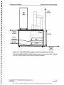
A
About
66 inches
Minimum
Front
Access
18 inches
30 inches
Network
Connection
110 YAC
60 Hz, 15 Amp
UPS
Minimum
Access
36 inches
Figure 3-2: ThermoFluor® 384 system, stand-alone placement side view.
The power receptacle should be located within four feet of the rear of the system. Optional
network connection should also be located at the rear of the system.
Copyright © 2001 3-Dimensional Pharmaceuticals, Inc.
Confidential
Artisan Scientific - Quality Instrumentation ... Guaranteed | (888) 88-SOURCE | www.artisan-scientific.com
3-5
May 2001
4
4
Installation and Calibration
ThermoFlour® 384 Operating Manual
I
I
i
4
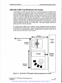
Alternate Table Top Placement and Access
An alternative is to install the system base plate on a tabletop rather than the supplied stand.
In this configuration the system pase plate with the ThermoFluor® 384 instrument and the
plate processing system attached is located on a table with the front of the instrument facing
to the right. The system base plate must have .the leveling feet installed on the corners and be
leveled in both front to back and side-to-side directions. It is very important that nothing
restricts or blocks the airflow through the gap between the system base plate and bench top
created by the leveling feet. This opening ensures proper airflow to the instrument. It is also
necessary to provide a minimum of 6 inches between the side of the instrument with the fan
where the cabling exits and any wall or splash plate. This ensures adequate clearance for
cabling and airflow from the instrument.
4
4
4
I
4
4
4
4
The universal power supply, control computer, monitor, keyboard and mouse are placed to
the immediate left of the instrument. The power receptacle should be located within six feet
of the rear of the universal power supply. Optional network connection should also be
located at the rear of the system control computer.
30 inches
WALL
30 inches
4
4
I
I
I
I
I
I
or
Minimum
AISLE
66 inches
4
I
4
I
I
I
TF 384
Minimum
Clearance
6 inches
4
I
I
I
I
4
I
I
Minimum
36 inches
4
4
4
I
I
Figure 3-3: ThermoFluor® 384 system, table top placement and access
Copyright © 2001 3-Dimensional Pharmaceuticals, Inc.
Confidential
Artisan Scientific - Quality Instrumentation ... Guaranteed | (888) 88-SOURCE | www.artisan-scientific.com
3-6
May 2001
a
a
a
Installation and Calibration
ThermoFlour® 384 Operating Manual
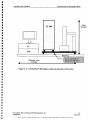
A
About
38 inches
Bench Top
Minimum Access
66 inches
DO NOT RESTRICT
OR BLOCK OPENING
Figure 3-4: ThermoFluor® 384 system, table top placement front view.
Copyright © 2001 3-Dimensional Pharmaceuticals, Inc.
Confidential
Artisan Scientific - Quality Instrumentation ... Guaranteed | (888) 88-SOURCE | www.artisan-scientific.com
3-7
May2001
4
4
Installation and Calibration
ThermoFlour® 384 Operating Manual
4
4
System installation
a
This section provides information and procedures for installing the ThermoFluor® 384
4
system. It includes unpacking and setting the system up. The system setup includes:
Power Up the System
System Initialization
Install the Filter(s)
Focus the Camera
When the installation is complete the system will be ready for operation.
4
4
4
4
Unpack the System
The ThermoFluor® 384 system is packed in two custom crates. One crate contains the
ThermoFluor® 384 instrument and plate processing system attached to the instrument base
plate. The second crate contains the system stands, NT Workstation, and universal power
supply. Please save these crates upon receipt of the instrument!
This is the factoiy
recommended method of transport for the instrument
Before installing the system inspect the crates and contents for signs of damage.
a
a
4
I
Step
i
Action
2
Visually inspect for any external damage. Any damage should be immediately
reported to the shipping company as well as 3-Dimensional Pharmaceuticals, Inc.
3
If any shock or temperature indicators are on the crate, locate and note their
status.
4
Locate a row of Philips head screws along all four sides of the crates,
approximately 5 inches from the floor. Black circles around each screw identify
them.
a
Set both crates on the floor with 4" x 4" support beams on the bottom.
i
4
I
I
I
4
a
5
Remove these screws from all four sides of each crate and store in a safe place.
6
Gently lift the top of the crates straight up, over and off the instrument. Caution,
the contents are still attached to the bottom of the pallet.
7
Inspect the contents of the crates for any signs of damage.
Remove Contents from Pallets
Remove the contents of the crates from the pallets. Install leveling feet on the system stand
and attach the instrument base plate to the system stand. Then place all packing materials
back in the crates and store for future use.
I
I
a
a
a
I
a
I
a
Step
i
Action
2
Remove the small shipping box secured to the system stand and pallet. Inside the
box are cabling, manuals, tools and four (4) stainless steel leveling feet for the
Remove the computer, monitor, and universal power supply shipping boxes from
the pallet and put them in safe location.
Artisan Scientific - Quality Instrumentation ... Guaranteed | (888) 88-SOURCE | www.artisan-scientific.com
a
4
a
Inspect for Damage
Copyright © 2001 3-Dimensional Pharmaceuticals, Inc.
Confidential
a
3-8
May 2001
I
I
I
I
I
I
I
a
Installation and Calibration
ThermoFlour® 384 Operating Manual
system stand. Remove the box and put it in safe location.
3
Unscrew the four bolts holding the system stand to the pallet. They are located on
both the right and left side of the system stand. The bolts are captured in the
pallet, so they will only drop half an inch or so from the pallet.
4
Prop up the front of the system stand with a 2" x 4" and install the front two (2)
leveling feet in place ofthe bolts.
5
Gently remove the 2" x 4" and set the system stand down on the two front
leveling feet.
6
Place the 2" x 4" under the back of the system stand and install the back two (2)
leveling feet in place ofthe bolts.
7
Gently remove the 2" x 4" and set the system stand down on all four leveling feet.
8
Gently lift the system stand offthe pallet and place it on the floor where the
system is to be located.
9
Remove the small shipping box secured to the instrument base plate Inside the
box are four stainless steel bolts for attaching the instrument base plate to the
system stand. Remove the box and put it in safe location.
10
Unscrew the four bolts holding the instrument base plate to the pallet. They are
located on both the right and left side of the instrument base plate. The bolts are
captured in the pallet, so they will only drop half an inch or so from the pallet.
11
Lift instrument base plate with the attached instrument and plate processing
system onto the system stand. Four persons, positioned at each corner of the
instrument, should lift and place the instrument onto the table. Proper lifting
techniques should be strictly followed during this procedure
CAUTION!!!
Lifting the instrument base plate onto the system stand
requires a minimum of four (4) persons.
12
Bolt the instrument base plate to the system stand.
13
Place the magazines for the microplates onto their bases.
14
Remove the shipping material holding the PlateCranelM robotic arm in place.
15
Open the top back panel and carefully remove the box labeled "FRAGILE - CCD
Camera" and place in safe location.
16
Unpack computer, monitor, and universal power supply from their shipping boxes
and place in safe location.
17
Place all packing materials on the pallets.
18
Replace the tops of the shipping crates onto the pallets and secure with the
screws.
19
The system is now ready for setup.
Copyright © 2001 3Dimensional Phannaceuticals, Inc.
Confidential
Artisan Scientific - Quality Instrumentation ... Guaranteed | (888) 88-SOURCE | www.artisan-scientific.com
3-9
May2001
Installation and Calibration
ThennoFlour® 384 Operating Manual
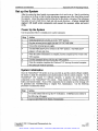
Set up the System
After the system has been located at an appropriate site it can be set up. Start by positioning
the system on the floor so that the plate processing magazines are at the front facing toward
the operator. Adjust the system stand leveling feet so the robotic work area of the instrument
base plate is level in both front to back and side-to-side directions. A factory trained field
engineer will install system components and connect the necessary cables and power
cords.
Power Up the System
Use the procedure below to initially power up the instrument.
Step
Action
i
Verify that all power switches are in the "OH" position.
2
Plug the universal power supply into the 110 YAC wall outlet.
3
Turn on the universal power supply.
4
Turn the PlateCraneTM power switch to the 'ON" position The PlateCraneTM
grippers will open and close.
5
When the system initialization is complete, turn the computer power switch to the
"ON" position.
6
Turn the instrument power switch to the "ON" position.
7
When the computer completes the WindowsTM NT boot up, the control computer
and system are ready for operation.
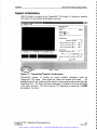
System Initialization
Once the ThermoFluor® 384 system is set up, powered up, and the control software installed,
the system is ready for initialization and synchronization with the control computer. As the
ThermoFluor® 384 Acquire 3.0 software launches, it searches for several available
components in the ThermoFluor® 384 system. These include the Camera, thermo-cycler
heater, and barcode reader. If any of the components fail to initialize an error message will
be generated (see Troubleshooting in Chapter Five, Maintenance).
Use the following
procedure to initialize the system.
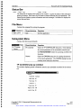
Step
Action
i
To run the system first boot up the NT workstation. A Startup screen similar to
the following will appear:
2
Log on as specified by the System Administrator.
Copyright © 2001 3-Dimensional Pharmaceuticals, Inc.
Confidential
Artisan Scientific - Quality Instrumentation ... Guaranteed | (888) 88-SOURCE | www.artisan-scientific.com
3-10
May 2001
Installation and Calibration
Start
ThermoFlour® 384 Operating Manual
...J Euploring - 3OPnew
mJ
3:28PM
Step
Action
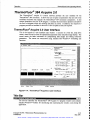
3A
Launch the ThermoFluor® 384 Acquire 3.0 software by clicking on its icon. See
above. The ThermoFluor® 384 Acquire 3.0 screen will appear.
or
-.:] kccsotiøs
-J HP -DiagTooIr
j Slortup
TFAcquire
Comund Prompt
Irdmnet Erlorer
Vi,
J Outlook Erpreso
TestController
-
Wwdowo NT Errptorer
A&nrrrrtrabve Toots tOonroon)
-
Corntrol RocketPo,t PookotModerri
.
HP Lock
-
Ptiotomotrios
-
Startup
-
Total Control for Wrrdowtr
Wrotows NT tipda&a
Docsnet
Settings
Erd
JJ
stt:
3B
Sht Down
Etodng - Tcw
1ft57AM
Launch the ThermoFluor® 384 Acquire 3.0 software by clicking the Start menu
button then Programs then TFAquire. See above. The ThermoFluor® 384
Copyright © 2001 3-Dimensional Phannaceuticals, Inc.
Confidential
Artisan Scientific - Quality Instrumentation ... Guaranteed | (888) 88-SOURCE | www.artisan-scientific.com
3-11
May 2001
Installation and Calibration
ThennoFlour® 384 Operating Manual
IAcquire 3.0 screen will appear.
I3ßPs ThennoFlu
file Subsystems
fAcquire version 3
Images
Eeperimeral Parameters
Data Directory
Browse
¡I:\Data\
Sample InFormation
PletelD:
Comment:
Heatg Parameters
HeatirMe:
J
(0233.0258]: 1=0
Scale Bitm
lBorr=0
tivuI=0
50
Temp. ncr., Low Temp. ('C]: ¡2
¡30
High, Low Temp Holds (sec]: J60
¡60
Image Parameters
Esposure Time (sec), IlIReps.: Ja5
.:I
Filters:
SC Image
Error
Heater
Camera
IUpIDown
Initial, Final Temperatures ('C): ¡40
¡500-3orvn
'Box
Gairo
Run
¡1
<xj
zJ
ir
Error
Error
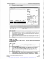
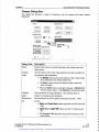
Step
Action
4
As the program launches, it searches for several available components inside the
ThermoFluor® 384 system. There are indicator fields for the heater and camera at
the lower left comer of the screen.
5
Upon successful initialization the system is ready for the remainder of the setup
process.
Install the Filter
Use the procedure below to install the filter. The system software must be running to
accomplish this task.
Step
Action
i
If it is not already open, open the optical compartment by removing the screws
from the rear panel.
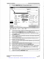
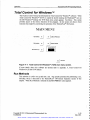
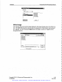
2
If the filter wheel is already in position 1 go to step 4. If it is not in position 1,
click on the arrow for the right hand Filters drop down menu in the image
parameters section at the lower right of the ThermoFluor® 384 Acquire 3.0
window. See Below.
3
Select Position 1 (500 ± 30 nm) from the drop down menu for the standard
ThermoFluor filter supplied with the instrument. See figure below. The filter
Copyright © 2001 3-Dimensional Pharmaceuticals, Inc.
Confidential
Artisan Scientific - Quality Instrumentation ... Guaranteed | (888) 88-SOURCE | www.artisan-scientific.com
3-12
May 2001
Installation and Calibration
I
ThermoFlour® 384 Operating Manual
wheel will rotate to that position.
m3DPm ThetntoFluar .TAcqsiic vson 3.tLIR.
file Subsystems Images
.
4::
:
x
Experimental Parameters
.3
Data Directory
Browse
Sample lnlormation
Platelû: 1
Comment:
HeatNg Parameters
Heatn Mode: lup/Down
Initial. Final Tempmatures ('C):
Temp. ncr., Low Temp. )C):
70
40
ji
25
Hgh. Law Temp Holds (sec): Il 80
-J
(0759,0009): 1=0
Scale Bitmap
lBoe=0
tt0vtl=0
Exposure Time (sec). NReps.:
Fillers:
SC Image
Uninitialized
Heater
Uninitialized
2/I/01
160
lmae Parameters
o
..J
(
Bain:
14
None
None
"J l-B ii
Run
t
530 +- 20 nm
470 +- 30 nm
10:12AM
Locate the standard ThermoFluor filter supplied with the instrument and place it
in the filter wheel at position i with the writing right side up.
CAUTION
The filter is a sensitive optical item and should be
handled by the edge with care
Secure the filter wheel filter cover over the filter.
Close the optical compartment door and secure with screws.
Focus the Camera
Use the procedure below to focus the camera. The system software must be running to
accomplish this task.
Step
i
2
Action
If it is not already open, open the optical compartment by removing the screws
from the rear panel.
Place a white piece of paper with small print on the thermal cycler block. To do
this manually open the light tight door as follows:
From the Acquire 3.0 SUBSYSTEM menu select Camera. The CAMERA
dialog box appears.
Copyright © 2001 3-Dimensional Pharmaceuticals, Inc.
Confidential
Artisan Scientific - Quality Instrumentation ... Guaranteed | (888) 88-SOURCE | www.artisan-scientific.com
3-13
May 2001
Installation and Calibration
I
ThermoFlour® 384 Operating Manual
Click the Open Door button. The light tight door opens
:ie
hum 3UP's themioFluo IFAcquire velai
File
Images
r ï:
- rJE
Experimental Parametern
Cernera
Data Directory
Browse
Sample Information
PlatelD:
Camer
Setup
Thermotluor Box
Get Info
Configure
Eeposure
Speedlab
rametero
Open Door
Close Door
Light On
Light Oft
ial Temperatures ('C):
Integrate Image
sec
Exposure Time:
Heafng Mode lUp/Down
ow Temp Holds (sec): ji 80
Light Indicator
70
40
lncr., Low Temp. ('C): ji
25
160
ameters
Single
Scale Bitmap
e Time (sec).
Conf.
J
CaIibate Image
r
FIeps.: 110
j4
J
Create New Calibration File
Enisolon Filter:
0:1
.JINone
Cmbo1
I
Gain:
1H
Run
l-Box IX.?) f9
IT
j
C
1/30/01
3:32 PM
3
Once the piece of paper is placed on the thermal cycler block close the light tight
door by clicking the Close Door button in the CAMERA dialog box.
4
From Acquire 3.0 CAMERA dialog box turn ON the IJV light source by clicking
the Light On button.
5
Enter an exposure time (one second) for the camera in the Integrate Image section
of the CAMERA dialog box.
6
Click on the Cont. button to have the camera start taking a continuous series of
images with the given exposure time.
7
From the rear of the instrument adjust the bottom adjustment ring on the lens until
the image is sharp.
8
Close the optical compartment door and secure with screws.
9
Turn OFF the UY light source by clicking the 11g ht OfO button.
10
Remove the white piece of paper from the thermal cycler block. To do this open
the light tight door by clicking the Open Door button in the CAMERA dialog
box as done above.
11
Once the piece of paper is removed from the thermal cycler block close the light
tight door by clicking the Close Door button.
Copyright C) 2001 3-Dimensional Pharmaceuticals, Inc.
Confidential
Artisan Scientific - Quality Instrumentation ... Guaranteed | (888) 88-SOURCE | www.artisan-scientific.com
3-14
May 2001
Installation and Calibration
ThermoFlour® 384 Operating Manual
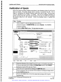
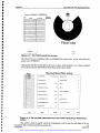
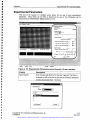
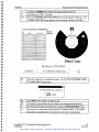
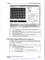
Calibration of Spots
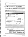
Before the system can properly measure microplates it must determine where the wells in the
plates are located. The system software must be running to accomplish this task. First an
image of a microplate with standard florescent beads in the wells is taken. Then the corner
wells are identified for the Acquire 3.0 program. After this the program calculates the
position of each of the 384 wells and scans the plate so the user can verifr that the program
has properly defined the well positions. Follow the procedure below to perform this
calibration.
Step
Action
i
From Acquire 3.0 open the light tight door as follows:
From the Acquire 3.0 SUBSYSTEM menu select Camera. The CAMERA
dialog box appears.
Click the Open Door button. The light tight door opens
Images
File
-r
Experimental Parameters
Camera
Dala Directory
Browse
Sample Intormation
PlatelD: 1
Setup
ThemoI tuer Bee.
Get Into
Conligure
Exposure
Speedlab
erameters
Healing Mode: IUoown
ial Temperatures ('Cl:
-Ii
70
40
Inc,.. Low Temp. ('Ct Il
Integrate Image
sec
Expooure Time:
ow Temp Holds (sed:
Light Indicator
25
1gO
IBa
ameters
l
Sine
Scale Bitmap
e Time (sec). tiReps.: 10
Cant.
J
Errssion Filler:
Calibrate Image
r
14
J
Create New Calibration File
ZJlNone
Cmbo1
)
Gain:
I-Bee
Run
<Y)
J9
[T
I
Test
Heater
2
Camere
Reedy
Idle
1130/01
3:32 PM
3
Place the microplate with standard florescent beads on the thermal cycler block.
Close the light tight door by clicking the Close Door button in the CAMERA
dialog box, type CLOSE and press <Enter>.
4
Turn ON the UY light source by clicking the Light On button.
5
Enter an exposure time (ten seconds) for the camera in the Integrate Image section
of the CAMERA dialog box.
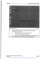
6
Click on the Single button to have the camera take an image with the given
exposure time.
Copyright © 2001 3-Dimensional Pharmaceuticals, Inc.
Confidential
Artisan Scientific - Quality Instrumentation ... Guaranteed | (888) 88-SOURCE | www.artisan-scientific.com
3-15
May 2001
Installation and Calibration
ThermoFlour® 384 Operating Manual
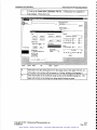
Click on the Create New Calibration File box. A
7
little green box [] appears in
the window. This is the I-box.
FAcquiieFile
Subuisterns
i
.,
mages
Experimental Parameters
Cernera
- Data Directorr
Browse
Sample Information
Plate ID:
Camerç)*)t
Sett
Theimof tuoi Box
-
Get lfo
Configure
¡
memeters
ial Temperatures (C
Speedlab
Exposure
Heating Mode: jUpJDown
CloseDoor
OpenDoor ¡
LightOn
Lightütt
¡40
¡70
lcr., Low Temp. (t): 11
25
Integrate Image
sec
Exposure Time
ow Temp Holds (sec): ¡180
Light Iridicaor
¡so
ameters
Scale Bitmap
Sine J
e Time (sec), UReps.: ¡10
Coot.
Errssion Fitter:
Calibrate Image
E Create New Calibration File
5:1
¡4
ZiINooe
Cmbo1
.Doc
Gain:
<,'r')
Run
Test
Heater
8
Camere
Reedy
Idle
1/30101
3:32 PM
Move the I box (the small green box in the image area) to the upper left well,
Al,
of the plate view section with the mouse by clicking, holding and dragging it.
9
Click Pick button in the Calibrate Image section of the Camera dialog box. The
upper left red dot on the dialog box image should change to green.
Copyright © 2001 3-Dimensional Pharmaceuticals, Inc.
Confidential
Artisan Scientific - Quality Instrumentation ... Guaranteed | (888) 88-SOURCE | www.artisan-scientific.com
3-16
May 2001
Installation and Calibration
ThermoFlour® 384 Operating Manual
3DPo ThermoFluor TFAcquire version 3.O.O
tl
file
Subsystems
Images
Experimental Parameters
- Data Directory
Browse
Sample Intocreation
PlatelD: 1
Setup
ment:
j
Thermofkmr Box
ting Parameters
Getlnto
Configure
Exposure
SpeedTab
OpenDoor
CloseDoor
Ii. Final Tempreatures ('C]: 140
Light Qn
I
Integrate Image
sec
Exposure Time
l
Single
Scale
'II
te Parameters
125
Il BO
posure Time (sec). NReps.: 110
Emission Filler:
C.
Create New Calibration File
Filters:
zJ
Cmbo1
\J$e
O
emp. ncr.. Low Temp. (t):
lih, Low Temp Holds (sec):
mage
. C'
l
zi
70
Light Ott
Light Indicator
Conf
*
Healing Mode: up/Down
ISO
14
None
l-Soc (XX)
Oain:
Run
I
cL
Pick
Camera
Reedy
Idle
10
Move the I box to the upper right comer, A24, of the plate view section with the
mouse.
11
Click Pick button in the Calibrate Image section of the Camera dialog box. The
upper right red dot on the dialog box image should change to green.
12
Move the I box to the lower right comer, P24, of the plate view section with the
mouse.
13
Click Pick button in the Calibrate Image section of the Camera dialog box. The
lower right red dot on the dialog box image should change to green.
14
Move the I box to the lower left comer, Pl, of the plate view section with the
mouse.
15
Click Pick button in the Calibrate Image section of the Camera dialog box. The
lower left red dot on the dialog box image should change to green.
16
Click the Test button in the Calibrate Image section of the Camera dialog box.
The I box will start to move across the screen covering all 384 well locations.
17
Visually verify that the I box remains centered on the wells as it moves. This
confirms the program has correctly defined the position of each well.
Click Save to save this calibration. NOTE: As long as the camera or thermal
cycler block are not moved this calibration should not have to be done again.
18
19
From Acquire 3.0 CAM ERA dialog box manually tum OFF the UY light source by
clicking the Light Off button.
20
Remove the microplate from the thermal cycler block. To do this open the light
Copyright © 2001 3-Dimensional Pharmaceuticals, Inc.
Confidential
Artisan Scientific - Quality Instrumentation ... Guaranteed | (888) 88-SOURCE | www.artisan-scientific.com
3-17
May2001
Installation and Calibration
ThermoFlour® 384 Operating Manual
tight door by clicking the Open Door button.
21
Once microplate is removed from the thermal cycler block manually close the
light tight door by clicking the Close Door button.
22
Properly store the microplate.
Copyright © 2001 3-Dimensional Pharmaceuticals, Inc.
Confidential
Artisan Scientific - Quality Instrumentation ... Guaranteed | (888) 88-SOURCE | www.artisan-scientific.com
3-18
May 2001
Installation and Calibration
ThermoFlour® 384 Operating Manual
Acceptance Tests
)
This test is ran to validate the proper operation of the ThermoFluor® 384 instrument. The
system and analysis software must be running to accomplish this task. For a procedure to
prepare and run plates, and then analyze the data refer to Tutorial Seven in the Tutorial
Manual.
I
I
,
The most fundamental measurement giving meaningful data using ThermoFluor® is the LTm
between a well containing compound and a reference well (Tm,+comp. - Tm, ref). Since the Tm is
independent of initial and final fluorescent intensities, validation of ThermoFluor®
instruments should be based on the uniformity of Tm across the entire heating block.
Accuracy Test
To measure uniformity of Tm across a plate, uniform assay plates of bovine Carbonic
Anhydrase II (Sigma, catalog #C2522, E.C. 4.2.1.1) should be made using the conditions
listed below. These conditions were chosen to give a wide working range of Tm'S, (40°C -
70°C), while using an inexpensive protein and a procedure that can be accomplished
relatively quickly (1 day or less).
Condition i (Tm
40°C):
5 j.tl of 0.15 mg/ml Carbonic Anhydrase in 50 mM NaOAc,
100 mM NaC1, pH 4.4, 1 mM EDTA, 50 j.tM 1, 8 ANS,
1
overlayed with 3 .tl oil.
Condition 2 (Tm
50°C):
1
5 p.! of 0.15 mg/ml Carbonic Anhydrase in 50 mM NaOAc,
100 mM NaCl, pH 4.5, 50 p.M ZnC12 , 50 p.M 1, 8 ANS,
overlayed with 3 p.1 oil.
I
)
I
I
)
I
Condition 3 (Tm
60°C):
5 p.1 of 0.15 mg/ml Carbonic Anhydrase in 25 mM NaPIPES,
100 mM NaCI, 1 mM EDTA, pH 7.0, 50 p.M 1, 8 ANS,
overlayed with 3 p.! oil.
Condition 4 (Tm
70°C):
5 p.1 of 0.15 mg/mI Carbonic Anhydrase in 25 mM NaPIPES,
100 mM NaCI, 50 p.M ZnCl2, pH 7.0, 1 mM Acetazolamide,
50 p.M 1, 8 ANS, overlayed with 3 p.! oil.
The ThermoFluor® Instrument parameters for measuring the thermal denaturation in this test
should be:
Ramp Mode, heating 25-85°C, in 1°C increments.
High temperature equilibration for 0.25 min (1 Ss).
Fluorescent intensity averaged over 4, 1 Os exposures.
Acceptance shall be achieved when deviation across a plate (measured as the standard
deviation in the Tm of 384 wells) is <0.2°C.
Uniform plates for the latter three conditions have a long shelf life and will give identical
results after freeze-thaw (-80°C, 1 week).
)
These tests can also be run in step mode (O. 1mg/mi protein is sufficient) but it will take longer.
The lot number for the CAlI that 3DP have is l00K9279. loo mgs is $493.50 (at 0.15mg/mi, Sul
volume this comes to 350ug/plate (including 20% excess); using the indicated conditions, each plate
uses $1.72 of protein.
Copyright © 2001 3-Dimensional Pharmaceuticals, Inc.
Confidential
S
Artisan Scientific - Quality Instrumentation ... Guaranteed | (888) 88-SOURCE | www.artisan-scientific.com
3-19
May 2001
Installation and Calibration
ThermoFlour® 384 Operating Manual
Precision Test
To measure the precision of the instrument as well as the accuracy a test is run as follows:
A total of three plates are run using the third set of conditions described for the
accuracy tests above, on two consecutive days, with deviations in absolute T on
the same instrument to be < 1.0°C.
A minimum of one plate will be run under the third set of conditions in step mode.
Copyright © 2001 3-Dimensional Pharmaceuticals, Inc.
Confidential
Artisan Scientific - Quality Instrumentation ... Guaranteed | (888) 88-SOURCE | www.artisan-scientific.com
3-20
May 2001
Installation and Calibration
ThermoFlour® 384 Operating Manual
Chapter Four
Operation
Overview
This chapter will familiarize the user with the basic operation of the ThermoFluor® 384
system.
Specifically, this chapter includes the following sections:
Safe Operation
Operating Software and Controls
ThermoFluor® 384 Acquire 3.0
ThermoFluor® 384 System Operation
The following table identifies the appropriate section to read in order to learn how to properly
operate the ThermoFluor® 384 system.
To learn more about ...
Read the section....
General considerations for safe operation of
the system
Safe Operation
4- 2
System operating software and controls
Operating Software and
Controls
4- 3
Total Control for WindowsTM.
Total Control for
4- 10
See page
WindowsTM
ThermoFluor® 384 Acquire 3.0 user interface.
ThermoFluor® 384 Acquire
3.0
4- 18
Basics of ThermoFluor® 384 system operation
ThermoFluor® 384 System
Operation
4-29
Copyright © 2001 3-Dimensional Pharmaceuticals, Inc.
Confidential
4-1
May 2001
Artisan Scientific - Quality Instrumentation ... Guaranteed | (888) 88-SOURCE | www.artisan-scientific.com
Operation
ThermoFlour® 384 Operating Manual
Safe Operation
The ThermoFluor® 384 system should be set up and run by 3-Dimensional Pharmaceuticals
Inc. factory trained personnel only. If you are not factoiy trained, contact 3-Dimensional
Pharmaceuticals, Inc. at 1-610-458-8959 to schedule training.
The Operating Manual contains up-to-date information on the safe installation and operation
of the ThermoFluor® 384 system. Before installing or running the ThermoFluor® 384
system, completely and thoroughly review the latest version of the Operating Manual. If any
instructions are unclear or unfamiliar to you, contact 3-Dimensional Pharmaceuticals, Inc. at
1-610-458-8959 for clarification and proper operation.
4
4
4
4
Please locate and identify all safety and informational labels on the instrument. If any labels
are missing, smudged or damaged, discontinue use and contact 3-Dimensional
Pharmaceuticals, Inc. for replacements.
Please locate and identify all safety items on the instrument including covers and panels. If
any items are missing, damaged or disabled in any way discontinue use and contact 3Dimensional Pharmaceuticals, Inc. for instrument repair.
Abnormal instrument operation should be immediately noted and instrument use discontinued
until examined by a representative from 3-Dimensional Pharmaceuticals, Inc.
As with all laboratory equipment, follow all standard operating procedures and policies. An
operations and maintenance logbook should be maintained at the instrument's location.
WARNING
i
Do not place hand into the öpen Light Tight Compartment door.
If it were to shut on the hand it could cause serious injury.
Remember, above all, safety first!!!
4
4
4
4
4
4
4
4
a
4
I
Copyright © 2001 3-Dimensional Pharmaceuticals, Inc.
Confidential
Artisan Scientific - Quality Instrumentation ... Guaranteed | (888) 88-SOURCE | www.artisan-scientific.com
4-2
May 2001
a
4
4
4
a
4
a
Operation
ThermoFlour® 384 Operating Manual
Operating Software and Controls
As mentioned in Chapter 2, Construction and Function, the WindowsTM NT Workstation
contains the software that controls the operation of the system. The Total Control for
WindowsTM (TCW) program coordinates the overall operation of the system while the
ThermoFluor® Acquire 3.0 program provides the user interface to the ThermoFluor® 384
instrument. Total Control for WindowsTM directly operates the plate processing system and it
indirectly operates the ThennoFluor® 384 instrument through a DDE connection with the
Thennopluor® Acquire 3 0 control software The ThermoFluor® Acquire 3 0 control
software interfaces with the CCD camera and an embedded controller (ZworldTM) in the
ThermoFluor® 384 instrument that controls the filter wheel, UV light source light tight
compartment door and the thermal cycler heater This is illustrated below
WindowsTMNT Workstation
Total Control for
thermoFi uor®
Icquire3.O
WîndôwsTM
ThermoFluor® 384
Instrument
I
PlateCrane
Barcode
ILReader
J
Plate Processing System
eatet
Figure 4- 1: Operating and control software applications.
Copyright © 2001 3-Dimensional Pharmaceuticals, Inc.
Confidential
Artisan Scientific - Quality Instrumentation ... Guaranteed | (888) 88-SOURCE | www.artisan-scientific.com
4-3
May 2001
Operation
ThennoFlour® 384 Operating Manual
System Initialization
After the system is powered up, the ThermoFluor® 384 Acquire 3.0 software is launched.
The Acquire 3.0 user interface screen appears, see below.
t
3D1"s The,moFIuo TfAcquìid?version 3.0.0
File
Subsystems
mages
Eaperimental Parameters
Data Directory
If:\Data
Sample Information
PlatelD:
Comment:
Hear
Parameters
HeaMode: IUp/D
E
lniti. Final Temperatures (C): 140
Temp. ncr., Low Temp.
rc)
Hii. Low Temp Holds (sec):
50
130
12
60
160
Image Parameters
Scale Sitmap
(04S.C18S) l76
IBorw68646O
Exposure Time (sec). tiReps.: 05
0Ovfl0
Filters:
SC Image
Error
Heater
Camera
Error
1117100
j
j
I' Gain:
j500+'3Onm
l-Bort
Run
Il
,Y) fj
.j
T'
IblError
8:45AM
Figure 4-2: ThermoFIuorAcquire 3.0 manScreen.
ThermoFluor® Acquire 3.0 searches for several available components inside the
ThermoFluor® 384 system. These include the Camera and thermal cycler heater.
The
embedded controller. will position the filter wheel to its home position and open the light tight
compartment door. The camera and heater initialization is indicated at the lower left bottom
of the screen, see above. After this is done the TCW application is started and it's MAIN
menu appears. See below.
Copyright © 2001 3-Dimensional Pharmaceuticals, Inc.
Confidential
Artisan Scientific - Quality Instrumentation ... Guaranteed | (888) 88-SOURCE | www.artisan-scientific.com
4-4
May 2001
Operation
ThermoFlour® 384 Operating Manual
MAIN ME ¡J
Run Methods
Edit Methods
F2
F4
Cslihrate PlateCrane
F5
System Settings
Current Speed:
Edit Position List
in
Eec
Exit TCW
Figure 4-3: Total Control for WindowsTM (TCW) main menu screen.
Routine Analysis
Next the user enters experimental parameters. For a single plate these parameters can be
entered using the ThermoFluor® Acquire 3.0 user interface screen since TCW is not needed.
For a routine analysis of multiple plates TCW is used to set up the plate handling for the run
and enter experimental parameters, which are relayed to the ThermoFluor® Acquire 3.0
program. The ThermoFluor® Acquire 3.0 program communicates the appropriate parameters
to the embedded controller. If a filter wheel position is changed the embedded controller
repositions the filter wheel immediately. The user then initiates the run by clicking the Sta it
Run button on the TCW Current Method screen or the RUN button on the Acquire 3.0
interface screen.
Copyright © 2001 3-Dimensional Pharmaceuticals, Inc.
Confidential
Artisan Scientific - Quality Instrumentation ... Guaranteed | (888) 88-SOURCE | www.artisan-scientific.com
4-5
May 2001
Operation
ThermoFlour® 384 Operating Manual
Current Method: THERMOI
No.
Positioot:
Cui,'eitt ?1ate
Selected
Methods:
Plate C rane
tart Run
Esc
Figure 4-4: The TCW Current Run screen.
PlateCraneTM Loads Plate
The TCW program then checks the status of the instrument through Acquire 3.0. Once this is
done the PlateCraneTM goes to the input magazine, removes the top plate and loads it in the
instrument. TCW then signals Acquire 3.0 that a plate has been placed in the light tight
compartment. As the plate passes the barcode reader the barcode is read. This infonnation is
communicated to the Acquire 3.0 program. At the end of the run the Acquire 3.0 program
stores it with the experimental data in the TNT file in the directory designated when the
experimental parameters are entered.
Heater Cycle
The Acquire 3.0 program then signals the embedded controller to begin the run. The
embedded controller closes the door to the light tight compartment and begins heating
depending upon which heating mode, Up/Down or Continuous Ramp mode, is selected.
Up/Down Mode
In the UpiDown mode the temperature is raised to a high temperature value, held there for a
set time (High Temperature Hold Time) then lowered to the Low Temperature setting and
held there. The plate is held at the low temperature for a set time (Low Temperature Hold
Time) to allow equilibration and then while the camera records images. The embedded
controller repeats this process for each temperature point in the selected range.
The embedded controller begins the first heating cycle (Up/Down mode) by signaling the
heater to raise the temperature of the plate to the initially selected "High" temperature value.
When the controller senses this temperature has been reached it signals the heater to maintain
the "High" temperature and begins measuring the "High" temperature hold time. See below.
Copyright © 2001 3-Dimensional Pharmaceuticals, Inc.
Confidential
Artisan Scientific - Quality Instrumentation ... Guaranteed | (888) 88-SOURCE | www.artisan-scientific.com
4-6
May2001
Operation
ThermoFlour® 384 Operating Manual
TEMPERATURE
Shutter Closed Image
for background
correction
UY light ON
prior to End
of Low T
Hold
Second
High T Hold
Command issued
UV light off
Next cycle begins
JCycle begins
Low T Hold
Signal at End
of Low T Hold
Number of
replicate images
specified recorded
TIME
Figure 4-5: Up/Down mode sequence of events.
When this time has elapsed the controller signals the heater to lower the temperature of the
plate. When the controller senses this temperature has been reached it signals the heater to
maintain the "Low" temperature and begins the "Low" temperature hold time. Prior to the
end of the "Low" temperature hold the controller turns the UY light on so it can stabilize
before images are taken. When the "Low" Temperature Hold time has elapsed the controller
signals the Acquire 3.0 program.
During this time the Acquire 3.0 program polls the embedded controller for the signal that the
low temperature hold time is complete. When it finds this signal the Acquire 3.0 program
signals the camera to first acquire a "shutter closed image" (if selected) for background
correction. It then directs the camera to take the number of replicate images (typically 4)
with specified exposure times as indicated by the previously communicated experimental
parameters. When these are completed the Acquire 3.0 program sends a command to the
embedded controller. When the embedded controller receives the command it turns off the
UY light and begins the next heater cycle at the next higher temperature increment. These
cycles are continued until the cycle for the final temperature is completed.
Copyright © 2001 3-Dimensional Pharmaceuticals, Inc.
Confidential
Artisan Scientific - Quality Instrumentation ... Guaranteed | (888) 88-SOURCE | www.artisan-scientific.com
4-7
May 2001
Operation
ThermoFlour® 384 Operating Manual
Continuous Ramp Mode
In the Continuous Ramp mode the temperature is raised to a temperature value and held there
for a set time (High Temperature Hold Time) to allow equilibration and then while the
14
camera records images. Then the temperature is raised to the next temperature value and held
there to allow equilibration and then while the camera takes shots. The embedded controller
repeats this process for each temperature point in the selected range.
4
4
4
The embedded controller begins the first heating cycle (Continuous Ramp mode) by signaling
the heater to raise the temperature of the plate to the initially selected "High" temperature
value. When the controller senses this temperature has been reached it signals the heater to
maintain the "High" temperature and begins measuring the "High" temperature hold time.
See below.
I
I
4
4
4
TEMPERATURE
4
Shutter Closed Image
for background
correction
UY light ON
prior to End
of High T
Hold
Second
High T Hold
Cycle
begins
4
I
4
(
4
I
I
4
4
4
4
4
Command issued
UV light off
Next cycle begins
I
I
First
High T Hold
Signal at End
of High T Hold
Number of replicate
images specified
recorded
4
4
I
I
TIME
Figure 4- 6: Continuous Ramp mode sequence of events.
Prior to the end of the "high" temperature hold the controller turns the UY light on so it can
stabilize before images are taken. When the "high" Temperature Hold time has elapsed the
controller signals the Acquire 3.0 program.
During this time the Acquire 3.0 program polls the embedded controller for the signal. When
it finds the signal the Acquire 3.0 program signals the camera to first acquire a "shutter closed
image" (if selected) for background correction. It then directs the camera to take the number
of replicate images (typically 4) with specified exposure times as indicated by the previously
communicated experimental parameters.
When these are completed the Acquire 3.0
program sends a command to the embedded controller. When the embedded controller
receives the command it turns off the IJV light and begins the next heater cycle at the next
Copyright © 2001 3-Dimensional Pharmaceuticals, Inc.
Confidential
Artisan Scientific - Quality Instrumentation ... Guaranteed | (888) 88-SOURCE | www.artisan-scientific.com
4-8
May2001
4
4
4
4
4
4
4
4
4
4
4
4
4
Operation
higher temperature increment.
temperature is completed
ThennoFlour® 384 Operating Manual
These cycles are continued until the cycle for the final
Plate Done
When the Final temperature cycle for the plate has been completed the embedded controller
bnngs the heater block temperature back to 25°C (if itas not already there), opens the light
tight compartment door, and indicates the plate is done The Acquire 3 0 program recognizes
the indication the plate done, stops polling the controller and communicates that the plate is
done to the TCW program.
Complete Run
The TCW program then directs the PlateCraneTM to remove the plate from the heater block
and place it in the output storage magazine. It then directs the PlateCraneTM to take the next
plate in the input magazine and load it onto the heater block. As the plate passes the barcode
reader it is read and this information is communicated to the Acquire 3.0 program that stores
it with the experimental data. TCW then signals Acquire 3.0 that a plate has been placed in
the light tight compartment and the Acquire 3.0 program signals the embedded controller to
begin the measurements for the next plate. The embedded controller then repeats the above
steps for this plate. This process is repeated until all the plates are measured.
Copyright © 2001 3-Dimensional Pharmaceuticals, Inc.
Confidential
Artisan Scientific - Quality Instrumentation ... Guaranteed | (888) 88-SOURCE | www.artisan-scientific.com
4-9
May 2001
Operation
ThemioFlour® 384 Operating Manual
Total Control for Windows TM
The Hudson Control Group has developed the Total Control for WindowsTM software. When
Total Control for WindowsTM (TCW) is started by double clicking the PlateCraneTM icon on
the MS WindowsTM desktop the TCW Main menu screen appears See below This screen
provides access to the various functions of the program In this section we discuss those
functions that might be used during the operation of the ThermoFluor® 384 System
MAIN MENU
Run Methods
Edit Methods
F4
F2
Colibrote PteteCrane
System Settings
Current Speed:
Edit Position List
F3
in
Esc
Exil TCW
Figure 4-7: Total Control for WindowsTM (TCW) main menu screenS
If more details about this software are desired refer to Appendix A, Total Control for
WindowsTM, for the TCW manual.
Run Methods
This selection is used to set up and start a run. The specific procedure for performing a run,
including setup is discussed in the ThermoFluor® 384 System Operation section of this
chapter. When Run Methods is selected the Current Method: screen appears.
Copyright © 2001 3-Dimensional Pharmaceuticals, Inc.
Confidential
Artisan Scientific - Quality Instrumentation ... Guaranteed | (888) 88-SOURCE | www.artisan-scientific.com
4-10
May 2001
Operation
ThermoFlour® 384 Operating Manual
Current Method: THERMO1
Selected
Methods:
Step
Ne.
Positie,t:
Carrent Plater
Plate Crane
start Run
Eec
Figure 4-8: The TCW Current Run screen.
The title of the run is displayed after the Current Run: screen title. In the case above the
current run is THERMO1.
Clicking the Start Run button allows the user to select which method to run, create a method
run list and access the ThermoFluor Plate Setup screen shown below:
i
2
i
3
4
Thei'rnoFlour Plate Setup
Stack i
Plate i
Plate 2
Frfrle
Dota Directory:
c:\tc3dp\dsta\
Emission Filter
2
Excitation Filter:
2
Plate k
Operating Mode:
Initial Temperature:
Temperatura Increment:
1.00
reoxX
16
lOso Y:
16
Final Temperature:
25.00
Number of Replicates:
2
Imaging Temperature:
25.00
Gain:
2
Low Equilibration Time:
30.00
Shutter Closed:
N
High Equilibration Time:
30.00
Your message hors
Exposure Time:
Md
25.00
Insert
1.00
Qelete
dIt
Ecc
Figure 4-9: Set up plate parameters from the TCW ThermoFluor Plate setup
sc ree n
This screen is used to specif' which set of parameters will be used for each plate to be run.
Copyright © 2001 3-Dimensional Pharmaceuticals, Inc.
Confidential
Artisan Scientific - Quality Instrumentation ... Guaranteed | (888) 88-SOURCE | www.artisan-scientific.com
4-11
May2001
Operation
ThermoFlour® 384 Operating Manual
The system will begin processing Plate i using the set of parameters entered for Plate 1. It
will then proceed to Plate 2 using the set of parameters entered for Plate 2. It will continue
processing each plate with its corresponding set of parameters until it comes to the last
designated plate. If there are more plates in the stack in the magazine than designated on the
ThermoFluor Plate Setup screen then the system will use the last designated set of parameters
for the remaining plates Click on the plate number under Stacki on the screen to view the
set of parameters for a given plate The available functions for the screen are listed in the
table below
Function
Description
Add
Clicking the Add button adds another plate to the bottom of the
list.
Insert
Clicking the Insert but will insert a plate above the plate
selected.
Delete
Clicking the Delete button deletes the selected plate from the
list.
Edit
Clicking the Edit button opens the ThermoFluor Setup Screen
that is used for changing the parameters for the selected plate.
Clicking the Esc button Returns the user to the Current
Method: screen.
Esc
To change the parameters for a plate select the Edit button. The ThermoFluor Setup Screen
appears. See below.
ThermoFluor Setup Screen
c?tcw'3dpdate
Low Eq. Time: 35
Initial Temp:
High Eq. Time: 15
Temp. Increment: Il
Final Temp: [43
I
Exposure Time: [io
Conlinuous Ramp
I
Imaging Temp: 25
No. Replicates:
4
Your messne here
Gain: [2
Box ( Dimension:
Box "Y Dimension:
Esc
Yes
No
Figure 4- 10: Enter parameters for a plate on the ThermoFluor Setup screen.
This screen allows the user to:
1. Enter the path and directoiy for the data *.psq and *.jnt files to be stored. The *.psq files
Copyright © 2001 3-Dimensional Pharmaceuticals, Inc.
Conf dential
Artisan Scientific - Quality Instrumentation ... Guaranteed | (888) 88-SOURCE | www.artisan-scientific.com
4-12
May 2001
Operation
ThermoFlour® 384 Operating Manual
are the raw camera data and the *.int files are integration files created by the Acquire 3.0
program The folder in which these files are to be stored is designated here
Enter the appropnate Imaging Profile Parameters These fields are
Field
Description
Initial Temp:
The starting temperature in °C for measurements. This is the
first high temperature in the Up/Down mode or the start of the
temperature ramp in the Continuous Ramp mode.
Temp. Increments:
The temperature difference between measurements in OC.
Final Temp:
The last temperature in °C for measurements. This is the last
high temperature in the Up/Down mode or the end of the
temperature ramp in the Continuous Ramp mode.
Imaging Temp:
The temperature to which the heater returns the plate and
maintains in the Up/Down mode while images are taken. Also
referred to as the low temperature.
Low Eq. Time:
The time the low temperature equilibration is held, in seconds,
before exposures are taken in the Up/Down mode.
High Eq. Time:
The time the high temperature equilibration is held, in seconds,
before returning to the low temperature in the Up/Down mode.
Exposure time:
Time each replicate shot of the camera is exposed, in seconds.
Select the desired operating mode. The options are:
Options
Description
Up/Down mode
Cycles the sample between successively higher temperature
values and the low temperature value where images are taken.
Designed for proteins that irreversibly unfold.
Continuous Ramp mode
Takes the sample from one temperature value to the next
without lowering the temperature. Images are taken at each
temperature value. Designed for proteins that easily refold.
Refer to Chapter 2, Optimizing ThermoFluor® Conditions, in the Application Manual for the
appropriate use of the different modes.
Select the desired Emission Filter. The options are:
Options
Description
None
No filter is used.
500±30 nm
This is the standard filter that comes with the ThermoFluor®
384 instrument.
530 ±20 mn
470 ±30 nm
For use in viewing higher wavelength fluorescence.
For use in viewing lower wavelength fluorescence.
Copyright © 2001 3-Dimensional Pharmaceuticals, Inc.
Confidential
Artisan Scientific - Quality Instrumentation ... Guaranteed | (888) 88-SOURCE | www.artisan-scientific.com
4-13
May 2001
Operation
ThermoFlour® 384 Operating Manual
5.
Enter the appropriate System Parameters. These fields are:
Field
Description
No Replicates
The number of images of the well taken by the CCD camera
following the shutter closed image during each cycle in the
Up/Down mode.
Gain:
This represents the detection mode of the CCD camera:
i corresponds to High Signal to Noise Ratio Use for
bright plates
2 corresponds to High Dynamic Range. Standard use.
3 corresponds to High Sensitivity. Use for dim plates.
The system is set at 2 during installation.
6.
Enter the appropriate Integration Parameters. These values are usually set at installation.
They determine the area to be integrated when the Acquire 3.0 programs create the NT
files. These fields are:
Field
Description
IBox "X" Dimension
The width of the integration field used for each well
IBox "Y" Dimension:
The height of the integration field used for each well.
Enter User Comments, if any, in the text box provided.
Select rather the camera take a shutter closed image with each set of replicate images
during data acquisition to use for background correction. Select YES or NO for shutter
closed background correction images
Copyright © 2001 3-Dimensional Pharmaceuticals, Inc.
Confidential
Artisan Scientific - Quality Instrumentation ... Guaranteed | (888) 88-SOURCE | www.artisan-scientific.com
4-14
May 2001
p
Operation
I
I
I
ThermoFlour® 384 Operating Manual
Edit Methods
This selection is used to set up a Method. It should not be used in the normal operation of the
ThermoFluor® 384 system. If more details about this section of the software are desired
refer to Appendix A, Total Control for WindowsTM, for the TCW manual.
METHOD EDITOR
No.
2
Ese
Process Sequence for Method: TIIEIRMO1
Process Step:
Move Pom
Lid ltolder
Move To
Plate Tvoe
Run Barcode Scanner
Move Plate
1
Run ThermoFluor
5
Move Plate
Barcode
ThermoFluor
NONE
Assay Plate
-
ThermoFluor
Avoilotite t'roceso Steps:
Stack2
roì1obte
PostSess;
NONE
Assay Plate
Assocïate4
J.nstrumerns:
¿dd Step
Insert Step
Qeleto Step
Satje Method As
aave Method
Change Method
Figure 4- 11: The Method Editor screen ¡s used to setup methods. lt is not
used during normal operation.
Edit Position List
This selection should not be used in the normal operation of the ThermoFluor® 384 system.
If more details about this section of the software are desired refer to Appendix A, Total
Control for WindowsTM, for the TCW manual.
Calibrate PlateCraneTM
This selection opens the Calibration screen. See below.
The various positions the
PlateCraneTM moves to are set up from this screen. These positions should be established
when the system is initially installed and should not have to be adjusted or changed during
normal operation of the ThermoFluor® 384 system. It is possible that a crash of the system
could cause the Stack Position to be altered or lost. This could affect the PlateCraneîM's
ability to pick up plates. In this case the Stack Position would have to be re-taught (recalibrated) to the PlateCraneTM arm. Refer to Appendix A, Total Control for WindowsTM, for
the TCW manual to do this.
To verify the Stack Position is correct refer to the
Troubleshooting section of Chapter 5. Maintenance.
Copyright © 2001 3-Dimensional Pharmaceuticals, Inc.
Confidential
Artisan Scientific - Quality Instrumentation ... Guaranteed | (888) 88-SOURCE | www.artisan-scientific.com
4-15
May 2001
q
I
Operation
ThermoFlour® 384 Operating Manual
4
I
4
CALIBRATION
o±i Him,
4
4
v
Current Position:
Move to Point
4
4
4
Teach Point
I
4
J
Jogp
Rotate W
Retate CCW
Gripper CW
Jog flown
Teaching Speed:
4
70
4
4
Gripper CCW
speed
R Jog Distance: S.Odeg 2 Jog DIstance: 5.0 mm P Jog Distance: 5.Odeg
Change ff Jog
Change
Jog
Change
4
4
4
' Jog
4
Close Qripper
Liome Plate Crane
Save Points
NOTE: Teach STACK positions by jogging
the 2 axis DOWN at 20 % SPEED until
the LIMIT switch triggers. Then Jog UP
h.11
mm. then TEACH the position.
Press <SPACE BAR> to Halt Movement
Esc
Exit
Figure 4- 12: The Calibration screen is used to establish the PlateCrane
positions. This screen is not used during normal operation.
System Settings
This selection opens the PlateCrane System Setup screen. See below. The position of the
assay plates relative to the PlateCraneTM arm grippers (plate position) is set up from this
screen. These positions should be established when the system is initially installed and
should not have to be adjusted or changed during normal operation of the ThermoFluor® 384
system. However, if new plates are used this position should be verified and may need to be
reset. To verifr or reset the plate position, refer to the Troubleshooting section of Chapter 5.
Maintenance. If more details about this section of the software are desired refer to Appendix
A, Total Control for WindowsTM, for the TCW manual.
4
4
I
I
4
4
4
4
I
I
I
I
4
I
4
4
I
I
I
I
4
4
Copyright © 2001 3-Dimensional Pharmaceuticals, Inc.
Confidential
Artisan Scientific - Quality Instrumentation ... Guaranteed | (888) 88-SOURCE | www.artisan-scientific.com
4-16
May 2001
I
I
I
4
I
I
Operation
ThermoFlour® 384 Operating Manual
PlateCrane System Setup
Defined P'ate Types:
PUe Duscriptiori:
DaughterPlate
Fcrmt
Mother Plate
3B4well
384-well
96-well
test
96-well
Assay Plate
Plate Hgt
90
80
420
132
Current Speed:
Lid Hgt
20
20
30
20
Riss Hgt
140
1
0
60
90
Run speed
PlateCrane XL
Ask if Ready to Home
¿dd Plate
flelete Plate
Modify Plate
Ecc
Exit
Figure 4- 13: The PlateCrane system setup screen is used to establish the
position of the microplates. This screen is not used during normal operation.
Current Speed
This indicates the current speed of the PlateCrane robotic arm.
Copyright © 2001 3-Dimensional Pharmaceuticals, Inc.
Confidential
Artisan Scientific - Quality Instrumentation ... Guaranteed | (888) 88-SOURCE | www.artisan-scientific.com
4-17
May 2001
Operation
ThermoFlour® 384 Operating Manual
The rmoFIuor 384 Acquire 3.0
The ThermoFluor® Acquire 3.0 control software provides the user interface for the
ThennoFluor® 384 instrument. It allows the user to enter run parameters that are sent to the
embedded controller that operates the ThermoFluor® 384 instrument components. It also
accepts parameters from the TCW program. It initiates the instruments operation and allows
4
the user to designate where the resulting data files are saved. In addition, the Acquire 3.0
4
program provides an interface for the user to view the plates as they are exposed.
4
4
ThermoFluor®Acquire 3.0 User Interface
This is the Acquire 3.0 user interface main window. It consists of a Title bar, drop down
menus, status bar and a screen for experimental parameter entry and plate image display. The
menus access the basic commands for manipulating data images and setting subsystem
parameters. The menus are constructed using standard MS WindowsTM formatting and
1
functions.
4
I
3DPs ThermoEluo,TFMquire version 3M.D
file Subspstems Images
J
Errperirrmntal Parameters
Data Director1Drowse
Sample Information
PlatelD:
Comment J
Heating Paremetem
Heating Mod
Intiiat, Final Terreraturen rc
Temp. nor., Low Temp. ('C):
J
Scale Ditrnap
(0233.0258):
.0
lBog-0
011-U
J
lup/Down
::J
48
150
2
J30
High. Low Temp Holds (sec). JO
SClrrsage
Ji
J j5+ 30ren
F8ers:
Sein:
Error
4
IBox ):<.Y) jT
Run
4
4
4
4
4
I
I
I
loo
Image Parameters --
Erosure Time (sec). UReps.: Ja5
I
I
I
I
I
IbErrot
4
I
Heater
Camera
Error
1117100
4
4
8:45AM
Figure 4- 14: ThermoFluor® Acquire 3.0 user interlace.
Title Bar
I
30P'e ThermoFluot
TiAcquire viun 3.U.(I
The title bar identifies the ThermoFluor® 384 Acquire 3.0 program window and contains
standard WindowsTM buttons for minimizing and maximizing the window, and closing the
application.
Copyright © 2001 3-Dimensional Pharmaceuticals, Inc.
Confidential
Artisan Scientific - Quality Instrumentation ... Guaranteed | (888) 88-SOURCE | www.artisan-scientific.com
4-18
May 2001
I
a
I
I
4
I
Operation
ThermoFlour® 384 Operating Manual
Status Bar
Fie&:er
Cornera
1t/7UO
Error
9:28 AM
The Status Bar is located at the bottom of the window. It gives the status of the instrument
heater and camera. Bold letters for the heater or camera indicate they are operational. The
Status Bar also displays system information and error messages In addition it displays the
current date and time.
File Menu
Contains the command for exiting the program.
Menu Selection Function
Quit
Quit the application.
Subsystem Menu
Contains the following commands:
Menu Selection Function
TF Controller
Opens the TF CONTROLLER dialog box, which displays
the current parameters of the embedded controller and
the Test Controller button for accessing controller test
functions.
Opens the CAMERA dialog box for making adjustments
to the camera parameters. The CAMERA dialog box also
contains some instrument functions.
Camera
TF Controller pop up window
This window displays general information stored in the embedded controller for the current
run
wT .Çon 'lier
Generai
Heat Mode: Up/Down
initial Temp: 40
Final Temp: 70
Temp ncr.:
1
Image Temp: 25
High Eq. Time: 180
Low Eq. Time: SO
Copyright © 2001 3-Dimensional Pharmaceuticals, Inc.
Confidential
Artisan Scientific - Quality Instrumentation ... Guaranteed | (888) 88-SOURCE | www.artisan-scientific.com
4-19
May 2001
Operation
ThermoFlour® 384 Operating Manual
Camera Dialog Box
This dialog box provides a means of interacting with the camera and setting camera
parameters.
Setup
Thermofluor Sox
Get Info
Configure
Exposure
Speedlab
Open Door
Close Door
Light On
Light Off
Integrate Image
Exposure Time: fia
sec
Light Indicator
Single
J
Calibrate lmaoe
Create Ne
I
Calibration File
Move Selection
Tool to Eech
Cornici iid Click
the Pick flutton
Pick
Dialog Area
Description
Setup
Buttons allow access to camera information and camera setup entiy
dialog boxes
This area allows entry of the image exposure time and commands for
the camera to take a exposures.
The Single button instructs the camera to take a single image
that is displayed in the Image display area.
The Cont. button instructs the camera to take a continual
series of images.
Integrate
Image
When the Cont. button is selected it changes to Cancel after
the first image is taken. Click Cancel to stop taking images.
Calibrate
Image
ThermoFluor
box
This area allows for image calibration. See Calibrate Spots in
Chapter 3, Installation and Calibration.
This area allows the user to operate instrument functions. These
include:
Open and Close Door buttons open and close the light tight
door.
11g ht On and Light Off buttons turn the Uy lights on and
off
The Emission Filter drop down menu allows selection of the
desired filter.
Copyright © 2001 3-Dimensional Pharmaceuticals, Inc.
Confidential
Artisan Scientific - Quality Instrumentation ... Guaranteed | (888) 88-SOURCE | www.artisan-scientific.com
4-20
May 2001
Operation
ThermoFlour® 384 Operating Manual
Setup Díalog Boxes
The buttons in the setup area of the CAMERA Dialog box opens several dialog boxes that
allow camera configuration settings to be changed. Only appropriately trained personnel
should use the features in these dialog boxes for setup and maintenance of the system.
'Camera Settings
Serial Number: O
Get Info
The Get Info button on the CAMERA Dialog
14FF Capable: Always Qn
box opens the CAMERA SETTING pop-up
General
CCD Name: SenSys 0400
FT Capable: No
Well Capacity: i 9464
Summing Well: Absent
Cooling Mode: Air or Water
Preamp Delay: O me
Ma Set Tamp: 10.00 C
window.
This window displays various
camera settings as shown below.
PreFlash: O mo
Min Set Tamp: 10.00 C
Total Ports:
i
Current Temp: 10.00 C
Parallel Dimension
Premask: 4
Pixel Size (nm): 9000
Active Rows: 512
Pixel Sep. (nm): 9000
Postmask: 4
Total Rows: 520
Serial Dimension
Prescan: 14
Pixel Sloe (nmj: 9000
Active Pixels: 769
Pixel Sep, [nm) 9000
Postocan: 14
Total Pixels: 796
flera
Clearing
Configure
The Configure button on the CAMERA
Mode: PRE_EXPOSURE
Cycles: 2
Set
Dialog
box
opens
the
CAMERA
CONFIGURATION dialog box. This dialog
f
box allows various camera configuration
Shutter
parameters to be set as shown below.
Mode: IPRE_EXPOSURE
Open Delay (msI: 5
Close Delay (msj
10
5
Set
110
Set
Readout Speed. Gain
Speed Table Entry:
Readout Hate (MHzJ: 1.00
Dit Depth: 12
Other
Port: O
Gain:
-
PMode: NORMAL
Temp. Setpoint (Cl: 10.00
ADC Offset: 6100
10.00
Set
6100
Set
¡
J
Copyright © 2001 3-Dimensional Pharmaceuticals, Inc.
Confidential
Artisan Scientific - Quality Instrumentation ... Guaranteed | (888) 88-SOURCE | www.artisan-scientific.com
4-21
May 2001
ThennoFlour® 384 Operating Manual
Operation
Region Definition
Exposure
Serial Dimension
Offset:
Size:
O
768
Binning Factor:
Jo
Set
1766
Set
Ji
Set
J
CAMERA
J
Size:
Binning Factor:
Dialog box opens the
SETUP EXPOSURE dialog box.
This dialog box allows various
exposure parameters to be set as
Parallel Dimension
Offset:
The Exposure button on the
shown below.
O
512
1
Jo
Set
1512
Set
11
Sel
J
Defaults
f
Exposure Parameters
Mode:
TIMED
Exposure Time (sec):
10
Jia
Set
U Exposures in Seq.:
1
Ji
Set
J
Speed Table
Entry
Readout Rate (MHz)
Bit Depth
Port
O
0.5
12
O
1.0
12
J
Max. Gain
SpeedTab
The SpeedTab button on the
CAM ERA Dialog box opens the
SPEED TABLE dialog box.
This dialog box allows speed
table parameters to be viewed
and edited as shown below.
Copyright © 2001 3-Dimensional Pharmaceuticals, Inc.
Confidential
Artisan Scientific - Quality Instrumentation ... Guaranteed | (888) 88-SOURCE | www.artisan-scientific.com
4-22
May 2001
Operation
ThermoFlour® 384 Operating Manual
Images Menu
Contains the following commands for writing, reading and reintegrating raw camera data in
the form of *.psq files. These are designed for offline use.
Menu Selection Function
Images
Read Image...
Read Series...
Read Image
Opens the OPEN dialog box for the selection of a *.psq
file for retrieval. Used offline.
Read Series
Opens the SELECT IMAGE SERIES dialog box for the
selection of a series of *.psq files corresponding to the
Write Image...
Reintegral:e
Write Image
Reintegrate
data for a single plate at all temperatures. Used offline.
Opens the SAVE AS dialog box designate which directory
and what file name the current image should be saved to
as a *.psq file.
Used to reintegrate raw camera image files (*.psq)
offline Used to recover plate data or process plate data
from time-critical run modes. See the Recovering Plate
Data Following System Disruption topic in the
Troubleshooting section of Chapter 5, Maintenance.
Read Image
This selection allows raw camera data in the form of a single *.psq to be viewed in the Image
display area of the Acquire 3.0 interface. An Open dialog box with *.psq files already
selected allows a directory and file to be selected.
TFAcquire
Look in:
1118-1O-1.psq
111 81 O.2.psq
1118-1 O-3.psq
1118.1 O.4.psq
1118-1 O-S C. psq
File name:
Files of type:
upen
Phoomerics Image Sequences (.psq
r
Cancel
Open as !ead-ory
Read Series
This selection allows viewing of raw camera data in the form of a series *.psq files
corresponding to the data for a single plate at all temperatures. The SELECT IMAGE SERIES
dialog box opens to allow selection of a *.psq file from the series. By then clicking the
Select Series button the series of *.psq files corresponding to the selected file are
retrieved. This feature is also used is used in conjunction with the reintegrate feature. See
the Recovering Plate Data Following System Disruption topic in the Troubleshooting section
of Chapter 5, Maintenance.
Copyright © 2001 3-Dimensional Pharmaceuticals, Inc.
Confidential
Artisan Scientific - Quality Instrumentation ... Guaranteed | (888) 88-SOURCE | www.artisan-scientific.com
4-23
May2001
Operation
ThermoFlour® 384 Operating Manual
mage Series
D,ive:
n:
1118-1 0-1. psq
Program Files
TFAccuire- ìrr.
11181 02.psq
1118-1 0-3.psq
1118104.psq
111810-SC.psq
Write Image
This selection allows the current image displayed in the Image Display area to be written to a
file. The SAVE AS dialog box opens to allow the designation of the directoly and naming of
the.*.psq file. By then clicking the Save button the image is saved as a *.psq file in the
designated directoiy.
Save in:
J TFAcquire
1118-1 0-tpsq
1118-1 0-2psq
1118-1 0-3.psq
1118.1 04.psq
1118-1 0-SC.psq
File name:
Save asilype:
Save
Photometrics Image Sequences '.psq3
Cancel
E Open as !ead-only
Copyright © 2001 3-Dimensional Pharmaceuticals, Inc.
Confidential
Artisan Scientific - Quality Instrumentation ... Guaranteed | (888) 88-SOURCE | www.artisan-scientific.com
4-24
May 2001
Operation
ThermoFlour® 384 Operating Manual
Experimental Parameters
This area of the Acquire 3.0 interface screen allows for the user to enter experimental
parameters. These fields can be filled in directly by the user or the infonnation can be
relayed from the Thermo Fluor Setup Screen in TCW.
I3ElP's ThermoFluor TEAcqúiieversioa
Eile
Subsystems
i
Images
erimentaI Parameters
Data Directory
Orowse
:\Data\
Sample Information
Plate ID:
Comment:
Heang Parameters
Heabng Mode
lniaI, Final Temperatures
Up/Doeai
C)
I°
40
Temp. Incr., Low Temp ('C) j2
High, Lowlemp Holds (sec)
13°
isa
leo
05
Il
Image Parameters
l
Scale Bitmap
(04S6,01B5)
=76
IBoe=686,460
Exposure Time (sec). #Reps.
navll=o
Filters:
Gain:
SC Image
Error
Heater
Camera
Error
1117/00
_:J
j
1500 + 30 nm
I'Boe
Run
I
<,Y)
j'
jj"
IblError
8:45AM
Figure 4-15: Experimental Parameters area of Acquire 3.0 user interface.
Field(s)
Description
Data Directory
Enter the path and directory for the data *.psq and *.int files to
be stored or click on browse to open the Set Directory dialog box
to select the desired folder. See below
3 Set Data Directo
Data Directory
Drive:
Set Directory
Copyright © 2001 3-Dimensional Pharmaceuticals, Inc.
Confidential
Cancel
j
4-25
May 2001
Artisan Scientific - Quality Instrumentation ... Guaranteed | (888) 88-SOURCE | www.artisan-scientific.com
Operation
ThermoFlour® 384 Operating Manual
Field(s)
Description
Plate ID
The plate ID is an eight-digit number that correspond to the
barcode number.
Comments
Enter User Comments in the text box.
Heating Mode
Specify the heating mode from the drop down menu. The modes
are Up/Down or Continuous Ramp.
Up/Down Mode: Cycles the assay plate between
successively higher temperature values and the low
temperature value where images are taken Designed for
proteins that irreversibly unfold.
Continuous Ramp Mode: Takes the sample from
one temperature value to the next without lowering the
temperature. Images are taken at each temperature value.
Designed for proteins that easily refold.
Initial, Final
Temperature (°C)
This specifies the range of temperatures for the run.
Initial Temp: The starting temperature in °C for
measurements (First high temperature in Up/Down
mode).
Final Temp: The last temperature in °C for
measurements (Last high temperature in Up/Down mode)
Temp. Incr Low Temp
(°C):
Specify the temperature increments to be taken over the range of
temperatures specified above and the Low Temperature for the
Up/Down heating mode.
Temp. Increments: Temperature difference
between measurements in °C
Low Temp: The low temperature in Up/Down
mode that is held while images are taken. (Not used in
ramp mode.)
High, Low Temp.
Holds (sec)
Specify the High and Low Temperature Hold times for the
heating cycle.
High Temperature hold: The high temperature
equilibration or hold time in seconds for the cycle in
Up/Down mode.
Low Temperature hold: The low temperature
equilibration or hold time in seconds for the cycle in
Up/Down mode.
Exposure time(sec).
#Reps:
Specify the length of exposure for each image and the number of
replicate images at each temperature.
Exposure time: Time each replicate image is exposed in
seconds in Up/Down mode.
No. Reps: The number of images of the well taken during
each cycle in the Up/Down mode. Using an average of
replicate images may improve the overall signal to noise
ratio.
Copyright © 2001 3-Dimensional Pharmaceuticals, Inc.
Confidential
Artisan Scientific - Quality Instrumentation ... Guaranteed | (888) 88-SOURCE | www.artisan-scientific.com
4-26
May 2001
Operation
ThermoFlour® 384 Operating Manual
Filter
Select the desired emission Filter from the drop down menu. The
500 nm is standard equipment with ThermoFluor® 384
instrument.
SC Image:
This is selected to designate a shutter closed image tobe taken for
background subtraction.
Gain:
This represents the detection mode of the CCD camera:
i corresponds to High Signal to Noise Ratio. Use for
bnght plates
2 corresponds to High Dynamic Range Standard use
3 corresponds to High Sensitivity Use for dim plates
The system is set at 2 dunng installation
IBox "XY"
Specify the size of the integration area by designating Box 'X"
and Box "Y'
Box "X"Dimension The width of the
integration field used for each well
Box "Y" Dimension: The height of the
integration field used for each well.
Run button
Begins the run.
Copyright © 2001 3-Dimensional Pharmaceuticals, Inc.
Confidential
4-27
May 2001
Artisan Scientific - Quality Instrumentation ... Guaranteed | (888) 88-SOURCE | www.artisan-scientific.com
Operation
ThermoFlour® 384 Operating Manual
Image Display Area
This area of the screen displays the camera images. This allows the run to be monitored from
the Acquire 3.0 interface screen. It will also display *.psq files read offline using the Read
Image and Read Series selections of the IMAGES Menu.
i
3DPn ThennoFluor TFAcquim version :30JI4'
file S
Experimental Parametern
rr r r r
(.rò ì i
Date Directorp
Browse
!f:\Date\
b
'è ra
'è 'è
l'i
'è 'è.'è 'è 'è i 'è 'è 'è 'è
1vò 'è bò *Ó 'è*'è'è'è'è *'è***aC
ses
e... bòê'è1i*,ò,,.b ..U.
( t. 'è, *0'»S
b . .. o e, . s
*5'è S*S 5*0* s Sess, s'èse eSSS
ee
C 'è 4'è S * 'è 'è
aaaS5'è'è*'è'è'èe45
S.C.
.0 *'è5 S S SS
S S SS 5* * SSC
0*0555
S'è55a:5 55.55*5
ea
e # ...ø. 5S.* .4 .CS.
Comment:
Hextir
Parameters
Heating Mode:
Up/Down
Initial, Final Temperaturen CC]:
Temp. mrs., Low Temp.
S 0**5se 3* *55*
C*
9 .t*sss sses
, e.
Sample lnfcrmatisrr
Piale ID:
40
rc
50
30
12
High, Low Temp Holds (sec]: Iso
160
Image Parameters
Exposure Time (sec], UReps.: 05
Filters:
SC Image
Error
Heater
Camera
Error
11J7OO
zJ
I
I5O0+30nm
I.Bos
Gain:
Run
I
ri
r'1:
íii-
J
[9
IblError
8:45 AM
Figure 4- 16: Image Display area of the Acquire 3.0 user interface.
The intensity of an individual pixel can be viewed by placing the cursor over the particular
well. The intensity reading is displayed as 1= under the image. At the beginning of a run the
intensity of some pixels can be checked to verif' they do not saturate the camera. Moving
the cursor over the wells does this by verifying that the intensities are less than 4096.
Copyright © 2001 3-Dimensional Pharmaceuticals, Inc.
Confidential
Artisan Scientific - Quality Instrumentation ... Guaranteed | (888) 88-SOURCE | www.artisan-scientific.com
4-28
May 2001
Operation
ThermoFlour® 384 Operating Manual
The rmoFIuor 384 System Operation
The ThermoFluor® 384 system should be turned on at least 20 minutes before a run to allow
the system to warm up. After the run sheet is completed and the assay plates are placed in the
input magazine the screening run is set up in Total Control For WindowsTM (TCW). The
plates are then run and data files written to a designated directory. The ThermoFluor®
Analysis Software then analyzes these data files.
Typical Procedure for Performing a Screening Run
The following procedure represents the way a typical screening assay is conducted. This
procedure uses TCW to set up a run of multiple plates.
Step
Action
i
Complete a screening run sheet or other documentation of the run.
Turn on the ThermoFluor® 384 System in the following order:
Universal power supply.
2
Boot-up the NT workstation. The startup screen appears, see below.
Turn on the instrument
Turn on the PlateCraneTM.
Epre-
Start
,J EpIoring - 3DPnew
[
328 PM
3
Place the assay plates in the input magazine of the ThermoFluor® 384 system.
4
Open the ThermoFluor® Acquire 3.0 application by double clicking the
Copyright © 2001 3-Dimensional Pharmaceuticals, Inc.
Confidential
Artisan Scientific - Quality Instrumentation ... Guaranteed | (888) 88-SOURCE | www.artisan-scientific.com
4-29
May 2001
Operation
ThermoFlour® 384 Operating Manual
ThermoFluor® Acquire 3.0 icon.
The ThermoFluor® 384 Acquire 3 0 program opens
The instrument goes through an initialization.
Observe the screen to verify the heater and camera initialize properly..
Minimize the ThermoFluor® 384 Acquire 3.0 screen.
OP'sTh
FIe
tao lEA
íArrssìom
il
SrAsr,lmra
J
-EPserarmterr
DakeDecto.p
O'.Dala\
Sample Woreralice
PloleiD:
-Heelee Pmemrlmc
-
HeatirgModer
P Scetetlenap
)O233.O258
l-O
lBou.O
ttOyO.O
j
Terra IncoLewlene. rct
IJ
Hr.LowTempHoldc(sec
j
Enmares IEne (sec). ttRepc:
in 1r
SClnraa
p
Gaio
Camera
Errar
is$7/eo
.1
''
&5.-rsn
¡r--.j I Bec P<
Ens
Heater
UP/Dorm
Iroliol, Errai Terepmalranc)Ct ir jr-
bErros
Br45 ABS
Open the Total Control for WindowsTM (TCW) application by clicking on the
TCW icon. The Main Menu screen for TCW opens.
MAIN MENU
Run Methods
Fi
Edit Methods
F2
F
Calibrate PlateCrone
System Settings
Current Speed:
Edit Position List
F3
Esc
Exit TCW
Copyright © 2001 3-Dimensional Pharmaceuticals, Inc.
Confidential
Artisan Scientific - Quality Instrumentation ... Guaranteed | (888) 88-SOURCE | www.artisan-scientific.com
4-30
May 2001
Operation
ThermoFlour® 384 Operating Manual
6
Access the THERMOFLUOR PLATE SETUP screen. This is done by:
6A
Clicking the Run Methods button or press the <Fi> function key. The Menu
dialog box appears
Select Method to EDIT:
CREATE A NEW METHOD
OK
1131601Ml
ARMVALID
BARTEST
STACKTST
TEST
TESTRUN
J
Cancel
THERMO1.
THERMO2
6B
Select the appropriate method from the list and click OK. The CURRENT
METHOD screen appears.
Current Method: THERMO1
Step
No.
Selected
Positio,t:
CirentP1ate
Plate Crane
Start Run
I 6C
Esc
Click the Start Run button. The START RUN dialog appears.
Start RUN now?
es
io
J
Copyright © 2001 3-Dimensional Pharmaceuticals, Inc.
Confidential
4-31
May 2001
Artisan Scientific - Quality Instrumentation ... Guaranteed | (888) 88-SOURCE | www.artisan-scientific.com
4
4
Operation
ThermoFlour® 384 Operating Manual
J 6D
I
Click Yes or press <Enter>. The CREATE METHOD RUN LIST screen appears.
4
4
4
Create METHOD RUN LIST
4
1\Iethods to be Run:
No.
4
AvailaMe
Methode:
Method Name:
4
4
4
4
nelete method
I
4
I
I
I
I
To Create a RUN LIST:
CLICK on any of the
METHODS listed at RIGHT>
in the ORDER you wish to
I
run them.
I
Continue
6E
Select the desired method from the available methods list. It will appear under
the Methods to be Run list If the wrong method is entered, selecting it in the
Methods to be Run list and clicking the Delete Method button will delete it.
6F
When the desired method(s) have been selected click the Continue button The
IS THE METHOD LIST COMPLETE? Dialog appears.
I
I
I
I
I
I
I
Is the Method List complete?
Yes
6G
No
Click Yes or press <Enter>, The THERMOFLUOR PLATE SETUP screen
appears.
a
a
a
I
a
a
Copyright © 2001 3-Dimensional Pharmaceuticals, Inc.
Confidential
Artisan Scientific - Quality Instrumentation ... Guaranteed | (888) 88-SOURCE | www.artisan-scientific.com
4-32
May 2001
I
I
I
I
I
Operation
ThermoFlour® 384 Operating Manual
ThermoFlour Plate Setup
Stack I
I Plate i
Pla!e 2
Plate 3
k Plate k
2
Data Directory:
c:\tcw3dp\deta\
3
Emission Filter
Operating Mode:
Excitation Filter
Initial Temperature:
25.00
Box X:
16
LUD
IBox Y:
is
Temperature Increment:
Final Temperature:
26.00
Number of Replicates:
Imaging Temperature:
25.00
Gain:
Low Equilibration Time:
30.00
Shutter Closed:
Nigh Equilibration Time:
30.00
Your message here
Exposure Time:
Md
7
7A
N
1,00
Insert
edit
flelete
Ecc
Designate the plates and plate parameters to be run in TCW. This is done by:
Click the Add button to add Plate i to the Stacki list. If all the plates in the
Stack! magazine will use the default parameters go step 8.
7B
To change the parameters for Plate i click the Edit Button The THERMOFLUOR
SETUP Screen appears.
ThermoFluor Setup Screen
c'itcw'3dpdata
Initial Tamp: j40
Temp. Increment:
i
Final Temp: 43
Low Eq. Time: 35
Up/Down
High Eq. Time: jis
j
Continuous Ramp
Exposure Time: pio
Imaging Tamp: 125
No. Replicates:
4
Gain:
2
Box % Dimension:
jis
Box Y Dimension:
is
Your message here
j
Ecc
I
Copyright © 2001 3-Dimensional Pharmaceuticals, Inc.
Confidential
Artisan Scientific - Quality Instrumentation ... Guaranteed | (888) 88-SOURCE | www.artisan-scientific.com
4-33
May 2001
Operation
ThennoFlour® 384 Operating Manual
7C
Complete the ThermoFluor Setup Screen.
1.
Enter the path and directory for the data PSQ and Nf files to be stored.
2. Enter the appropriate Imaging Profile Parameters in the fields:
. Initial Temp The starting temperature in °C for measurements (First high
temperature in Up/Down mode).
. Temp. Increments: Temperature difference between measurements in °C
s Final Temp: The last temperature in 0C for measurements (Last high
temperature in Up/Down mode)
. Imaging Temp: The low temperature in Up/Down mode that is held while
images are taken.
Low Eq. Time: The low temperature equilibration or hold time in seconds
for the cycle in Up/Down mode.
High Eq. Time: Thehigh temperature equilibration or hold time in seconds
for the cycle in Up/Down mode.
Exposure time: Time each replicate image is exposed in seconds in
Up/Down mode.
3. Select the desired operating mode by clicking on the corresponding box.
Green indicates the selection.
4. Select the desired Emission Filter. The 500 mn is standard equipment with
ThermoFluor® 384 instrument.
5. Enter the appropriate System Parameters in the fields:
No Replicates The number of images of the well recorded dunng each
cycle in the Up/Down mode.
Gain amplification value This is usually set at installation i can be
used for particularly bright plates and 3 for particularly dim plates.
6. Enter the appropriate Integration Parameters in the fields. These values are
usually set at installation.
IBox "X" Dimension: The width of the integration field used for each
well.
IBox "Y" Dimension: The height of the integration field used for each
well.
7. Enter User Comments, if any, in the text box.
8. Select whether the shutter is opened or closed. Select YES for closed and
NO for Open. Green indicates the selection. Usually Closed at beginning of
run.
When complete press the <Esc> key. The THERMOFLUOR PLATE SETUP
screen appears.
7D
Click the Add button to add Plate2 to the Stack i list. If all the remaining plates
in the Stack 1 magazine will use the default parameters go step 8.
7E
To change the parameters for Plate2 click the Edit Button. The THERMOFLUOR
SETUP Screen appears. Repeat step 7C to designate the parameters for Plate2.
7F
Repeat steps 7D and 7E until all the parameters have been designated for all the
plates in the Stack i magazine. Ifa plate needs to be inserted, clicking the Insert
but will insert a plate above the plate selected. Ifa plate needs to be deleted,
Copyright © 2001 3-Dimensional Pharmaceuticals, Inc.
Confidential
Artisan Scientific - Quality Instrumentation ... Guaranteed | (888) 88-SOURCE | www.artisan-scientific.com
4-34
May 2001
Operation
ThermoFlour® 384 Operating Manual
8
8A
clicking the Delete button deletes the selected plate from the list.
Start the run in TCW. To do this:
Exit the THERMOFLUOR PLATE SETUP screen by pressing the <Esc> key. The
CURRENT METHOD screen appears with the message "System is PAUSED".
Current Method: THER/IO1
Step
No,
Position:
Current P1ate
Selected
Methods
)
Plate Crane
System is PAUSED.
Terminate Run
8B
Press <SPACE BAR> to UNPAUSE System
Esc
Press the <spacebar> to unpause the system. The IS THE PLATECRANE CLEAR
TO HOME NOW? Dialog opens.
Is the PLATE CRANE clear to HOME now?
Yes
No
8C
Click Yes or press <Enter> to begin the run.
8D
The plates are run and data files are written to the designated data directory.
9
If it becomes necessary to terminate the run click the Terminate Run button.
The run can be monitored from the Acquire 3.0 interface screen. It will update
the status bar and display the well exposures in the plate imaging display.
10
Copyright © 2001 3-Dimensional Pharmaceuticals, Inc.
Confidential
Artisan Scientific - Quality Instrumentation ... Guaranteed | (888) 88-SOURCE | www.artisan-scientific.com
4-35
May 2001
Operation
ThermoFlour® 384 Operating Manual
I3DIs TheimoFluor TFAcquire version 3.0.0
File
Subspsterrrs
Images
Experimental Parameters
Data Directory
If:\Data\
Sample Irdrsmation
PletelD:
Comment
J
Healing Parameters
Healing Mode: JUplDoeai
lnilial, Final Temperatures ('C): 140
50
Temp. ncr., Low Temp. ('C): 12
30
High, Low Temp Holds foco):
60
J
Image Parameters
I
104S6.0185): 1=76
Scale Bitmap
IBox=686,460
Exposure Time (sec), Repo.:
ttOvfj=0
Filters:
SC Image
Error
Heater
Camera
Error
1117100
zi
j
¡
Aun
zi
fly' fl''
J500+.3Onm
l.Bos
Gain:
Il
0.5
<X)
IblError
84SAM
11
At the completion of the run remove the plates from the ThermoFluor® 384
system output magazine.
12
If the ThermoFluor® 384 system is not going to be used for an extended period of
time shut down the system.
13
Analyze the data files using the ThermoFluor® Analysis software. See
ThermoFluor® 384 Analysis Software Manual.
Performing a Single Plate Run with Acquire 3.0.
There may be times when it is necessary to run oniy a single plate and manually load it into
the ThermoFluor® 384 instrument. This can be done from the Acquire 3.0 program directly.
To do this follow the procedure below.
Step
Action
1
Complete the necessary run sheet.
2
Turn on the ThermoFluor® 384 System in the following order:
Universal power supply.
Boot-up the NT workstation. The startup screen appears, see below.
Turn on the instrument
Copyright © 2001 3-Dimensional Pharmaceuticals, Inc.
Confidential
Artisan Scientific - Quality Instrumentation ... Guaranteed | (888) 88-SOURCE | www.artisan-scientific.com
4-36
May 2001
a
Operation
ThermoFlour® 384 Operating Manual
p
I
I
p
a
a
p
a
p
I
T F-+
a
p
a
a
a
a
a
R,lT EH
a
I
a
a
I
Stadi
3
--
.4 Eoring -
!I
3:28 PM
Open the ThermoFluor® Acquire 3.0 application by double clicking the
ThermoFluor® Acquire 3.0 icon.
a
The ThermoFluor® 384 Acquire 3.0 program opens.
a
The instrument goes through an initialization.
Observe the screen to verify that the heater and camera initialize properly.
a
4
Place the assay plate on of the ThermoFluor® instrument heater block.
a
a
a
a
a
a
a
a
a
a
Copyright © 2001 3-Dimensional Pharmaceuticals, hic.
Confidential
Artisan Scientific - Quality Instrumentation ... Guaranteed | (888) 88-SOURCE | www.artisan-scientific.com
4-37
May 2001
Operation
ThermoFlour® 384 Operating Manual
3DPs ThermoFluor TFAcquirWerrrioP3íiO
t
Eile
Subsystems
Images
Experimental Parameters
Data Directory
jf:\Data\
Sample Inlormation
Plate ID:
Commert J
Heatlig Parameters
Heating Moda:
J
150
Temp. ncr.. Low Temp. [C): J2
130
High. Low Temp Holds (sect 160
lme Parameters
Scale Bitmap
Error
Error
11/7,00
--
-.
Ji
_:::j 1500+-30 rar,
J
SC Image
Camera
1Go
Exposure Time (sec). #Reps.: J05
Dvfl=0
Filters:
Heater
zJ
Up/Down
Initial Final Temperatures (CJ: 140
zJ
l-Boa PC?) JT JT
Gain:
Aun
Error
8:4SAM
5
Enter the experimental parameters using the Acquire 3.0 interface screen.
This is done by:
5A
Enter the path and directoiy for the data PSQ and INT files to be stored. By
clicking on the Browse button the SET DATA DIRECTORY dialog box appears
to select the desired folder.
SB
Enter the plate ID number. This is an eight-digit number that would correspond
to the barcode number.
5C
Enter User Comments, if any, in the text box.
SD
Specify the heating mode from the drop down menu. The modes are UpiDown or
Continuous Ramp.
5E
Enter the appropriate Heating Parameters in the fields:
Initial Temp: The starting temperature in °C for measurements (First high
temperature in Up/Down mode).
Final Temp: The last temperature in °C for measurements (Last high
temperature in Up/Down mode)
Temp. Increments: Temperature difference between measurements in °C
Low Temp: The low temperature in UpiDown mode that is held while
images are taken.
High Temperature hold: The high temperature equilibration or hold time in
seconds for the cycle in Up/Down mode.
Low Temperature hold: The low temperature equilibration or hold time in
seconds for the cycle in Up/Down mode.
Copyright © 2001 3-Dimensional Phannaceuticals, Inc.
Confidential
Artisan Scientific - Quality Instrumentation ... Guaranteed | (888) 88-SOURCE | www.artisan-scientific.com
4-38
May 2001
Operation
ThermoFlour® 384 Operating Manual
5F
Enter the appropriate Imaging Parameters in the fields:
Exposure time Time each replicate image is exposed in seconds in
Up/Down mode.
No. Reps: The number of images of the well recorded during each cycle in
the Up/Down mode
Select the desired emission Filter from the drop down menu. The 500 nm
is standard equipment with ThermoFluor® 384 instrument.
The remaining fields are usually set at installation. They are:
SC Image: This designates a closed shutter image be taken for background
subtraction.
Gain: amplification value (2). This is usually set to two at installation and
left. 1 can be used for particularly bright plates and 3 for particularly dim
plates.
IBox "X" Dimension: The width of the integration field used for each
well.
IBox "Y" Dimension: The height of the integration field used for each
well.
6
Click the Run button to begin the run. The light tight door closes and the run
begins. The plate is run and the data files are written to the designated data
directory.
7
The run can be monitored from the Acquire 3.0 interface screen. It will update
the status bar and display the well exposures in the plate imaging display area.
t3IW1 TheimoFluor TFAcquireisi
Eile
Subspstems
g
Images
Experimental Parametern
Data Directorr
It:\Data\
Sample Infoimetion
Plate ID:
Jj
Comment:
Hear,g Parametern
HearrgMode: Up/Done
tniti. Final Ternp&atures ('C):
Temp. lncr.. Low Temp. l'
l
Scale Bitmap
(04S6,018.: l.76
lBoe686,40
#Dvtt=C
'J
lma
Error
Error
11/7/00
30
so
Parameters
Exposure Time [sec), ifReps.: 10.5
SC Image
Camera
150
Hi, Low Temp Holds [sed: so
Filters:
Heater
40
12
z.1
[
Gain:
Il
500 i-30 nm
l-Gos
Run
,Y[ iir I:ii
IbtErrct
8:45 AM
Copyright © 2001 3-Dimensional Pharmaceuticals, Inc.
Confidential
Artisan Scientific - Quality Instrumentation ... Guaranteed | (888) 88-SOURCE | www.artisan-scientific.com
4-39
May2001
Operation
ThermoFlour® 384 Operating Manual
8
At the completion of the run the light tight door will open Remove the plate
from the ThermoFluor® instrument heater block
9
If the ThermoFluor® 384 system is not going to be used for an extended period of
time shut down the system.
10
Analyze the data files using the ThermoFluor® Analysis software. See
ThermoFluor® 384 Analysis Software Manual.
Copyright © 2001 3-Dimensional Pharmaceuticals, Inc.
Confidential
Artisan Scientific - Quality Instrumentation ... Guaranteed | (888) 88-SOURCE | www.artisan-scientific.com
4-40
May 2001
Operation
ThermoFlour® 384 Operating Manual
p
Chapter Five
p
Maintenance
p
p
p
I
p
p
p
I
I
p
I
p
p
Overview
This chapter provides information and instructions for the routine maintenance of the
ThermoFluor® 384 system.
Specifically, this chapter includes the following sections:
System Cleaning
Camera Focusing
Filter Changes
Light Source changes
Troubleshooting
Repairs
The following table identifies the appropriate section to read in order to learn how to perform
specific maintenance tasks or troubleshooting.
To learn more about ...
Read the section....
Cleaning the system
Focusing the camera
Changing filters
System Cleaning
Camera Focusing
Filter Changes
5-5
Changing a light source
Light Source changes
5-7
Troubleshooting the system
Repairing the ThermoFluor® 384 system
Troubleshooting
Repairs
5-8
Copyright © 2001 3-Dimensional Pharmaceuticals, Inc.
Confidential
See page
5-2
5-3
5-17
5-1
May 2001
Artisan Scientific - Quality Instrumentation ... Guaranteed | (888) 88-SOURCE | www.artisan-scientific.com
Maintenance
ThermoFlour® 384 Operating Manual
System Cleaning
The following cleaning procedures should be followed every three (3) months.
Internal Instrument Cleaning
Use the following procedure to clean the interior of the ThermoFluor® 384 instrument.
Step
Action
1
Shut down and disconnect power to the system.
2
Open the light tight compartment door and lock it in an open position.
3
4
Mix approximately 2 1/2 ounces of bleach with 1 gallon warm distilled water.
Dampen a cloth in the bleach solution.
5
Wipe all black anodized surfaces with a damp cloth.
6
Wipe any stainless steel components with the damp cloth.
7
Wipe and thoroughly dry all horizontal black anodized surfaces with a dry cloth.
8
Wipe and thoroughly dry the stainless steel components with a dry cloth.
9
Properly dispose of all clothes and cleaning materials when done.
External Instrument Cleaning
Follow the following procedure to clean the exterior of the ThermoFluor® 384 instrument.
Step
Action
1
Shut down and disconnect power to the instrument.
2
Dampen a cloth in glass cleaner solution.
3
Wipe all external surfaces on the instrument and around the plate processing
system with the damp cloth. Avoid any connectors, plugs or cables.
4
5
Wipe all external surfaces on the instrument with a dry cloth.
Wipe all horizontal black anodized surfaces around the plate processing system
with adamp cloth.
6
Wipe the stainless steel rods of the plate magazines with a damp cloth.
7
Wipe and thoroughly dry all horizontal black anodized surfaces around the plate
processing system with a dry cloth.
8
Wipe and thoroughly dry the stainless steel rods of the plate magazines with a dry
cloth.
5
Properly dispose of all clothes and cleaning materials when done.
Copyright © 2001 3-Dimensional Pharmaceuticals, Inc.
Confidential
5-2
May 2001
Artisan Scientific - Quality Instrumentation ... Guaranteed | (888) 88-SOURCE | www.artisan-scientific.com
Maintenance
ThermoFlour® 384 Operating Manual
Camera Focusing
Use the procedure below to focus the camera The system software must be runrnng to
accomplish this task
Step
i
Action
2
Place a white piece of paper with small pnnt on the thermal cycler block To do
this manually open the light tight door as follOws:
From the Acquire 3.0 SUBSYSTEM menu select Camera. The CAMERA
dialog box appears.
Click the Open Door button. The light tight door opens
If it is not already open, open the optical compartment by removing the screws
from the rear panel
r.Oj
D'*iIbeimoFIuo TFAcquire velsion 3.0
File
mages
Experimental Parameters
x Camera
Data Directory
Browse
Sample Intormation
Plate ID:
Cameia
Seti
Therrxrotluor Box.
mameters
Heming Mode: UP/Down
Getinfo
iat Temperatures (C]:
Exposure j
70
40
ncr.. Low Temp. ('C): Il
Integrate Image
Exposure Time:
sec
125
ow Temp Holds (sec]: 180
Light Indicator
ametero
Sirìe
l' Scale Bitmap
r
e Time (sec). l4lReps.: Il 0
Cor*.
Emission Filtec
Calibrate Image
Create New Calibration File
4
.IiINone
Cmbo1
l.Box
Sain:
Run
<.Y)
Fi
Fi
I
Text
Heater
Camere
Reedy
Idle
1130101
3:32PM
3
Once the piece of paper is placed on the thermal cycler block close the lIght tight
door by clicking the Close Door button in the CAMERA dialog box.
4
From Acquire 3.0 CAMERA dialog box turn ON the Uy light source by clicking
the Light On button.
5
Enter an exposure time (one second) for the camera in the Integrate Image section
of the CAMERA dialog box.
6
Click on the Cont. button to have the camera start taking a continuous series of
images with the given exposure time.
Copyright © 2001 3-Dimensional Pharmaceuticals, Inc.
Confidential
5-3
May 2001
Artisan Scientific - Quality Instrumentation ... Guaranteed | (888) 88-SOURCE | www.artisan-scientific.com
Maintenance
ThermoFlour® 384 Operating Manual
7
From the rear of the instrument adjust the bottom adjustment ring on the lens until
the image is sharp.
8
Close the optical compartment door and secure with screws.
9
Turn OFF the UY light source by clicking the Light Off) button.
10
Remove the white piece of paper from the thermal cycler block. To do this open
the light tight door by clicking the Open Door button in the CAMERA dialog
box as done above.
11
Once the piece of paper is removed from the thermal cycler block close the light
tight door by clicking the Close Door button.
Copyright © 2001 3-Dimensional Pharmaceuticals, Inc.
Confidential
5-4
May 2001
Artisan Scientific - Quality Instrumentation ... Guaranteed | (888) 88-SOURCE | www.artisan-scientific.com
Maintenance
ThermoFlour® 384 Operating Manual
Filter Changes
Use the procedure below to change a filter. The system software must be running to
accomplish this task.
Step
Action
i
Open the optical compartment by removing the screws from the rear panel.
If the filter wheel is already in the desired position go to step 4. If it is not in the
2
desired position click on the arrow for the right hand Filters drop down menu in
the images parameter section at the lower right of the ThermoFluor® 384 Acquire
3.0 window. See Below.
Thenuofluor TFcquirersion 3..
file
Subsystems
Images
Eeperimertial Parameters
_j
Data Directory
Sample Information
PlatelD:
Comment:
- Heating Parameters
Heating Mode: Up/Down
InitiaL Final Temperatures ('C): 140
17G
Temp. ncr., Low Temp. (t): Ii
125
High. Low Temp Holds (sec): 1180
so
Image Parameters
Scale Bilnr
(0759,0009): =0
IBox=0
Eeposure Time Iced. Reps.: 11G
Ovtl=0
Filters:
SClmage
4
None
l
J None
Gain:
1B1
ii
i
530 +-2Onm
Uninitialized
Heater
Uninitialized
2/I/01
Run
1N47° .
nm
10:12AM
3
Select the desired position from the drop down menu by clicking that position on
the listing. See the above figure. The filter wheel will rotate to that position.
4
Remove the filter wheel filter cover from over the filter.
5
Grasp the filter by the edge and remove from the filter wheel. Place in a safe
position or holder.
CAUTION!!!
Filters are sensitive optics and should be handled by the edge with
care
6
Locate the replacement filter, grasp it by the edge and place it in the filter wheel
Copyright © 2001 3-Dimensional Pharmaceuticals, Inc.
Confidential
5-5
May 2001
Artisan Scientific - Quality Instrumentation ... Guaranteed | (888) 88-SOURCE | www.artisan-scientific.com
Maintenance
ThermoFlour® 384 Operating Manual
position with the writing right side up.
CAUTION!!!
Filters are sensitive optics and should be handled by the edge with
care
7
Secure the filter wheel filter cover over the filter.
8
Close the optical compartment door and secure with screws.
9
Properly store the removed filter
Copyright © 2001 3-Dimensional Pharmaceuticals, Inc.
Confidential
5-6
May 2001
Artisan Scientific - Quality Instrumentation ... Guaranteed | (888) 88-SOURCE | www.artisan-scientific.com
Maintenance
ThermoFlour® 384 Operating Manual
Light Source Changes
Use the procedure below to change the light source.
i
Turn off power to the instrument.
2
Open the rear panel of the light tight compartment by removing the screws.
3
Disconnect the connectors to the Uy light source.
4
Grasp the UY light fixture by the supports and pull backwards The unit should
slide back and drop down from its mounting pins.
5
Secure the filter wheel filter cover over the filter.
6
Align the fixture with the mounting pins and slide forward until it is secure.
Reconnect the connectors to the UV light source.
8
Close the optical compartment door and secure with screws.
9
Turn on power to the instrument.
Copyright © 2001 3-Dimensional Pharmaceuticals, Inc.
Confidential
5_7
May 2001
Artisan Scientific - Quality Instrumentation ... Guaranteed | (888) 88-SOURCE | www.artisan-scientific.com
4
4
Maintenance
ThermoFlour® 384 Operating Manual
4
4
Troubleshooting
I
4
This section discusses some of the ThermoFluor® 384 system specific problems that might
occur and their possible solutions. These problems include:
Failure of a component to initialize.
Recovering plate data following system disruption.
4
4
4
Plate crane doesn't pick up plates.
For additional information about problems with specific components of the system refer to
their documentation that is supplied with the system.
Component Fails to Initialize
4
4
4
4
As the ThermoFluor® Acquire 3.0 program launches, it searches for the several available subsystems inside the ThermoFluor® system. These are the CCD camera, the PlateCraneTM,
thermal cycler heater, and the bar code reader. There are indicator fields for the heater and
camera at the lower left corner of the Acquire 3.0 screen. If any of these fail to initialize the
system will not function properly.
Thermal Cycler Heater
If the heater module fails to initialize, the following error message will appear:
4
I
4
I
4
I
4
4
4
4
iFAcquire
Techne(Thermo):SeridCmdCommand Timed Out 1219/99 2:16:28 PM
rmThermoFIuor:Form_LoadCouId not create heater object 12/9/99 2:16:28 PM
I
4
4
If this message appears restart the ThermoFluor® Acquire 3.0 program. If this does not solve
the problem contact 3-Dimensional Phannaceuticals, Inc. at 1-610-458-8959 for technical
support.
Camera
If the camera fails to initialize, the following error message will appear:
quvi
pLcam..open: Error 50: Error code = 50
I
I
I
I
I
I
4
I
4
4
4
I
I
If this message appears follow the procedure below.
Step
Action
i
Shutdown the NT workstation
2
Turn power OFF to the ThermoFluor® 384 Instrument
3
Turn power ON for the ThermoFluor® 384 Instrument
Copyright © 2001 3-Dimensional Phannaceuticals, Inc.
Confidential
4
q
5-8
May 2001
Artisan Scientific - Quality Instrumentation ... Guaranteed | (888) 88-SOURCE | www.artisan-scientific.com
4
a
a
a
a
Maintenance
ThermoFlour® 384 Operating Manual
4
Reboot the NT workstation.
5
Launch the ThermoFluor® Acquire 3.0 program.
6
Observe that the camera initializes in the indicator field at the lower left comer of
the Acquire 3.0 screen.
If this does not solve the problem contact 3-Dimensional Pharmaceuticals, Inc. at 1-610-4588959 for technical support.
Barcode Reader
If the barcode reader fails to initialize there will be no beep when TCW is started. Also the
red light will not come on when the PlateCrane moves a plate in front of the reader. If this
happens verify there is power to the barcode reader. If there is then restart the system. If this
does not solve the problem contact 3-Dimensional Pharmaceuticals, Inc. at 1-610-458-8959
for technical support.
PlateCranelM
If the PlateCraneTM fails to initialize, the following error message will appear:
ri
The PlateCrarie is not responding.
Please correct the problem.
Yes
If this happens verify there is power to the barcode reader. If there is then restart the system.
If this does not solve the problem contact 3-Dimensional Pharmaceuticals, Inc. at 1-610-4588959 for technical support. Contact 3-Dimensional Pharmaceuticals, Inc. at 1-610-458-8959
for technical support.
Copyright © 2001 3-Dimensional Pharmaceuticals, Inc.
Confidential
5.9
May 2001
Artisan Scientific - Quality Instrumentation ... Guaranteed | (888) 88-SOURCE | www.artisan-scientific.com
Maintenance
ThennoFlour® 384 Operating Manual
ThermoFluor® Instrument Recovery Upon an Error
If the ThermoFluor® 384 Instrument should fail because of an error follow the procedure
below
Step
Action
If the instrument fails, record the following information:
The exact error message, "word for word".
The state of the instrument.
Number of plates run
Remaining number of plates
Ifa plate was left in the instrument or not.
Is the door open or closed.
Is the IJV lights on or off.
What is the PlateCraneTM arm position (rotary, vertical and gripper).
2
Additionally, record all of the steps that were taken in the instrument recovery
process
3
Prior to closing the program:
A. Open the FOLDER named TFAquire on the C: drive.
B. Copy the file named TFAquire.Iog.
C. Paste it into a dated folder (IV1MDDYYTfli) in the designated "Test"
folder in the ThermoFluor folder on the D: drive on the same unit with
the date on it. If the Test folder does not exist, create one in the manner
outlined
D. Rename the freshly pasted TFAquire.log to TFAquíreMMDDYY.Log.
4
5
Close out of the program and restart it. This will reinitialize the instrument.
(Often a camera issue will ensue, if this is the case, see step 6).
If this still does not work:
A. Close the program
B. Shut down the instrument and wait 30 sec
C. Start the instrument, wait for it to finish its start up routine
D. Then restart TFAquire.
6
If the instrument still does not function properly, repeat step 7. However, prior to
restarting the instrument, reboot the computer. After a successful reboot, continue
as normal:
A. Restart the instrument
B. Then restart TFAquire
7
Upon success or failure, notify others of the activity. Include the:
Specific TF unit
Error message that was recorded
Copyright © 2001 3-Dimensional Pharmaceuticals, Inc.
Confidential
5-10
May 2001
Artisan Scientific - Quality Instrumentation ... Guaranteed | (888) 88-SOURCE | www.artisan-scientific.com
Maintenance
ThermoFlour® 384 Operating Manual
Steps taken to address the error
Error log
Current state of the instrument.
Recovering Plate Data Following System Disruption
The Reintegrate command found under the IMAGES menu in the ThermoFluor® Acquire
3.0 application can be used to recover data for a plate if the system experienced a disruption
after the initial images for a plate were taken but before TCW finished running the method
for that plate. If the system is disrupted during image collection that data will be lost.
Step
Action
1
Open the ThermoFluor® Acquire 3.0 application.
2
Select Read Images from the IMAGE menu. The OPEN dialog box appears.
3DPs ThennoFluor TFAcquire version
t
Ele
.... .
r
w.
-.
Subeysf ems
Eperimer*aI Parameters
Data Directory
ea Senes...
Write Image...
8rwse
Reintegrate
Sample Intormation
PlatelD:
Look n:
J TE4cquire
J
Comment
1118-1 0-1 .psq
1118-lo-a psq
Heatig Parameters
1118-1 0-3.psq
1118-1 0-4.psq
11 18-10-SC.psq
Heating Mode: IUWDown
Initial. Final Tempmatures (C1:
File flame:
Files cf fype:
Qpen
Photometrics Image Sequences (.psqJ
E Open aniead-onlp
Cancel
J
70
125
High. Low Temp Holds (sec): 180
60
Image Parameters
Eaposure Time (sec). ItReps.: 110
.J
Filters:
SC Image
Ready
3
40
Temp. ncr.. Low Temp. rC) Il
I
6am:
4
None
I-Boe VY) Jj
Run
[j
I
Select any image file (*.psq) from the series of images files for the desired plate
from the corresponding data directory using the OPEN dialog box. Press OPEN
or double click the file listing.
The appropriate information is automatically entered in the Experimental
Parameter panel of the ThermoFluor® Acquire 3.0 screen.
The first replicate of the first temperature increment for the plate is
displayed in the Plateview panel. The first replicate image of each
temperature increment can be viewed using the scroll bar.
4
Select Reintegrate from the IMAGE menu. A check will appear next to the
Copyright © 2001 3-Dimensional Phannaceuticals, Inc.
Confidential
5-11
May 2001
Artisan Scientific - Quality Instrumentation ... Guaranteed | (888) 88-SOURCE | www.artisan-scientific.com
4
4
Maintenance
ThermoFlour® 384 Operating Manual
4
command on the menu.
Click Run at the bottom of the Experimental Parameter panel of the
ThermoFluor® Acquire 3.0 screen. The application runs the integration on the
raw image data for the plate and writes the corresponding *.int files. These files
can then be analyzed by the ThennoFluor® Analysis software application.
5
I
i
4
I
I
4
Plate Crane Doesn't Pick up Plates
This is an indication of a mechanical problem. Examine the PlateCraneTM arm and grippers
for abnonnalities. Also, if the system crashed, the stack (storage magazine) or plate position
in the TCW program could have been altered.
Verify Stack Position
The stack position is set up by the technician when the system is initially installed. It should
not have to be done again under normal operating conditions. To verify that the stack
position in the TCW program is correct follow the procedure below.
Step
i
4
I
4
I
I
I
I
I
4
4
Action
Select the Calibrate PlateCrane (F4) button on the MAIN menu of TCW.
The Calibration screen will appear.
CALIBRAT ION
r
Positio,t Net,
Current Position:
It;-
___.±
Move to Point
'Z':
P':
Teaching Speed:
Rotate W
Rotate CCW
pecd
'R' Jog Distance: 5.Odeg 'Z' Jog Distance: 5.0 mm P Jog Distance: 5.Odeg
Change'ß' Jog
Change'' Jog
Change '' Jog
J
Close Qripper
lome Plate Crane
Save Points
NOTE: Teach STACK positions by Jogging
the 'Z' axis DOWN at 20% SPEED until
the LIMIT switch triggers. Then Jog UP
h.fl
mm. then TEACH the position.
Press <SPACE BAR) to Halt Movement
Ese
Exit
Home the arm by selecting Home Plate Crane button. The plate arm will
move to its home position.
Copyright © 2001 3-Dimensional Pharmaceuticals, Inc.
Confidential
5-12
May 2001
Artisan Scientific - Quality Instrumentation ... Guaranteed | (888) 88-SOURCE | www.artisan-scientific.com
I
I
4
I
I
I
I
I
4
I
I
I
I
I
I
I
I
I
I
I
I
I
I
I
I
I
I
Maintenance
3
4
ThermoFlour® 384 Operating Manual
Select the desired stack location on the Calibration screen. For example, Stack 1.
Click the Move to Point button on the Calibration screen.
Move to Safe?
5
6
7
Select Yes in the MOVE TO SAFE? confirmation pop-up dialog box. The arm
should move over the plate at the bottom of the desired stack.
Verify the grippers are positioned properly over the plate (In a position to pick
up the plate)
Click the Close Gripper button on the Calibration screen to venfy they gnp the
plate.
8
Select the stack in question on the Calibration screen and click the Move to
Point button.
9
Select Yes in the MOVE TO SAFE? confirmation pop-up dialog box. The arm
should lift the plate and return it to the bottom of the magazine stack.
10
If this is done successfully there is no problem with the stack position calibration.
Exit the Calibration screen by clicking the Esc/Exit button.
11
If the arm doesn't line up over the stack correctly refer to Appendix A, Total
Control for Windows1M, for the procedure to re-teach (recalibrate) this position to
the arm.
Verify or Reset Plate Position
When the Plate processing system is first set up the position of the assay plates relative to the
PlateCranelM arm grippers (plate position) is set. When the type of plates are changed or
possibly following a crash of the system the plate position may need to be verified or reset.
To verify or reset information about plate position follow the procedure below.
Step
i
Action
2
Click the System Settings (F6) button on the MAIN menu of TCW. The
PlateCrane System Setup screen appears.
3
Click Add to add new plate dimensions.
4
Enter the plate name in the ENTER THE NEW PLATE NAME/DESCRIPTION
pop-up dialog box. Click OK.
Open the TCW program by double clicking its icon on the MS Windows1M
desktop.
Copyright © 2001 3-Dimensional Pharmaceuticals, Inc.
Confidential
5-13
May 2001
Artisan Scientific - Quality Instrumentation ... Guaranteed | (888) 88-SOURCE | www.artisan-scientific.com
Maintenance
ThermoFlour® 384 Operating Manual
Enter the new plaie Name/Description:
OK
The M EN U dialog box appears to enter plate specifications format. Default
5
designations for 96, 384, and 1536 well plates are shown Select the desired plate
specifications format and click OK. The ENTER THE PLATE TO PLATE
HEIGHT pop up dialog box appears
lEiìter the Plate-to-Plate HEIGHT 1mm):
Select FORMAT:
96weIl
132OOOOO
OK
f
Enter or verify the plate height in the ENTER THE PLATE TO PLATE HEIGHT
pop-up dialog box Stack a minimum of 10 plates and measure their height in
millimeters then divide the height by the number of plates to get the average
height of the plates. Enter the average plate height value in mm and click OK.
Caution
This is s very important parameter.
The measurement should be done accurately.
The Enter Plate Lid HEIGHT pop-up dialog box appears.
Enter Plate Lid HEIGHT Im mJ:
2IJOUOOU
OK
Copyright © 2001 3-Dimensional Pharmaceuticals, Inc.
Confidential
f
5-14
May 2001
Artisan Scientific - Quality Instrumentation ... Guaranteed | (888) 88-SOURCE | www.artisan-scientific.com
Maintenance
7
ThermoFlour® 384 Operating Manual
Ifa lid is used enter or verify the plate lid height in mm (default assumes no lid)
in Enter Plate Lid HEIGHT pop-up dialog box. Click OK. The Enter
Gripper Rise HEIGHT pop-up dialog box appears.
Enter Gripper Rise HEIGHT (mmi:
&00000u
OK
8
9
Enter or verify the gripper rise height in Enter Gripper Rise HEIGHT pop-up
dialog box. When the arm moves to pick up a plate it lowers until the center of
the arm touches the plate stack and the limit switch stops the movement. The arm
then rises to where the grippers are aligned with the top plate. The distance the
arm must rise for plate to align with the notches in the grippers is the gripper rise
height. This height should be 2 0 mm for the current 384 well assay plate.
Following entries click the Es/Exit button to return to the PlateCrane System
Setup screen. The SAVE CHANGES? confirmation pop-up dialog box appears.
Save Changee?
10
Click Yes to save the changes. The new plate setup should be visible on the list
on the PlateCrane System Setup screen.
Copyright © 2001 3-Dimensional Pharmaceuticals, Inc.
Confidential
5-15
May 2001
Artisan Scientific - Quality Instrumentation ... Guaranteed | (888) 88-SOURCE | www.artisan-scientific.com
Maintenance
ThermoFlour® 384 Operating Manual
PlateCrane System Setup
Defined Plate Types:
Piste Descriptio:
Format
Plate Hgt
Current Speed:
Lid Hgt
Rise Hqt
420
20
20
30
60
132:
2P
8O
Daúghter Plate
384-well
Assay Plate
384-well
90
80
Mother Plate
98-well
384-well
140
130
9B-weIl132209C.
70
Run speed
PlateCrane XL
Ask if Ready to Home
Md Plate
J11
elcte Plate
Modity Plate
Esc
Exit
Press Esc/ Exit button to return to the MAIN menu screen.
Copyright © 2001 3-Dimensional Phannaceuticals, Inc.
Confidential
5-16
May 2001
Artisan Scientific - Quality Instrumentation ... Guaranteed | (888) 88-SOURCE | www.artisan-scientific.com
a
a
a
a
I
Maintenance
ThermoFlour® 384 Operating Manual
Repair
There are no user repairable items in this system.
instrument
repair
is
required,
please
contact
If you suspect
3-Dimensional
Pharmaceuticals, Inc. at 1-610-458-8959.
a
a
a
a
a
a
a
a
H1
a
a
a
a
a
a
a
a
a
a
a
a
a
a
a
a
a
a
a
a
a
a
a
Copyright © 2001 3-Dimensional Pharmaceuticals, Inc.
Confidential
5-17
May 2001
Artisan Scientific - Quality Instrumentation ... Guaranteed | (888) 88-SOURCE | www.artisan-scientific.com
Maintenance
Copyright © 2001 3-Dimensional Pharmaceuticals, Inc.
Confidential
ThermoFlour® 384 Operating Manual
5-18
May 2001
Artisan Scientific - Quality Instrumentation ... Guaranteed | (888) 88-SOURCE | www.artisan-scientific.com
a
a
a
a
a
Appendix A
Total Control for Windows
a
a
a
a
a
a
a
a
a
a
a
a
a
a
a
a
a
a
Overview
This appendix contains detailed information about the control software Total Control for
Windows used for the ThermoFluor® 384 system.
Specifically, this appendix includes the following sections:
Total Control for Windows
Manual
The following table identifies the appropriate section to read in order to learn more about a
specific area.
p
To learn more about ...
Read the section....
a
a
The Total Control for Windows control
software
Total Control for
Windowsm Manual
See page
A-2
p
p
a
Copyright 2001 © 3-Dimensional Pharmaceuticals, Inc
Confidential
A-1
May 2001
Artisan Scientific - Quality Instrumentation ... Guaranteed | (888) 88-SOURCE | www.artisan-scientific.com
Copyright 2001 © 3-Dimensional Pharmaceuticals, Inc
Confidential
A-2
May 2001
Artisan Scientific - Quality Instrumentation ... Guaranteed | (888) 88-SOURCE | www.artisan-scientific.com
Appendix B
Hudson Group,
Plate Crane Manual
Overview
This appendix contains the Hudson Group, PlateCraneTM Manual with detailed information
about the Hudson Group, PlateCranem used in the ThermoFluor® 384 system.
Specifically, this appendix includes the following sections:
PlateCrane
Manual
The following table identifies the appropriate section to read in order to learn more about a
specific area.
To learn more about ...
The Hudson Group, PlateCrane
Read the section....
Manual
Copyright 2001 © 3-Dimensional Pharmaceuticals, Inc
Confidential
PlateCrane
Manual
See page
B-2
B-1
May 2001
Artisan Scientific - Quality Instrumentation ... Guaranteed | (888) 88-SOURCE | www.artisan-scientific.com
4
4
4
4
4
4
I
4
I
I
4
I
4
I
I
I
4
4
4
4
I
I
4
I
I
I
I
I
I
I
I
I
I
I
I
I
I
I
Copyright 2001 © 3-Dimensional Pharmaceuticals, Inc
Confidential
B-2
May 2001
Artisan Scientific - Quality Instrumentation ... Guaranteed | (888) 88-SOURCE | www.artisan-scientific.com
Appendix C
Consumables List
Overview
This appendix contains a list of consumables that are used in the operation of the
ThermoFluo? 384 system.
Specifically, this appendix includes the following sections:
Consumables List
The following table identifies the appropriate section to read in order to learn more about a
specific area.
To learn more about ...
Read the section....
Recommended Consumables
Consumables List
Copyright 2001 © 3-Dimensional Pharmaceuticals, Inc
Confidential
See page
2-2
C-1
May 2001
Artisan Scientific - Quality Instrumentation ... Guaranteed | (888) 88-SOURCE | www.artisan-scientific.com
Appendix C
ThennoFlour® 384 Operating Manual
Consumables List
Description
Manufacturer
Mgf. Tel. No.
Plate, PCR, 384 well, PP, blk
MJ Research, Inc.
l-888-735-8437
Neutral Disinfectant and Detergent
Misco Products Company
Didecxyl dimethyl ammonium chloride
Dimethyl benzyl ammonium chloride
Water
l-800-548-4568
Glass Cleaner
Isopropyl alcohol
2-Butoxyethanol
Anionic surfactant
Dye
Water
Ammonium hydroxide
l-800-548-4568
Misco Products Company
Distilled Water
Bar code labels
Copyright 2001 © 3-Dimensional Pharmaceuticals, Inc
Conf dential
Artisan Scientific - Quality Instrumentation ... Guaranteed | (888) 88-SOURCE | www.artisan-scientific.com
C-2
May 2001
Appendix D
ThermoFlour® 384 Operating Manual
Copyright 2001 © 3-Dimensional Pharmaceuticals, Inc
Confidential
C-3
May 2001
Artisan Scientific - Quality Instrumentation ... Guaranteed | (888) 88-SOURCE | www.artisan-scientific.com
w w w w w w w w w w w w w w w w w w w w w ww w w w w w w w w w w w w w w w w w w w w w w
Artisan Scientific - Quality Instrumentation ... Guaranteed | (888) 88-SOURCE | www.artisan-scientific.com