1
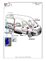
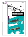
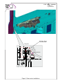
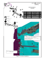
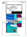
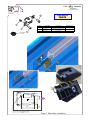
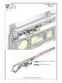
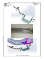
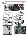
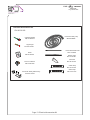
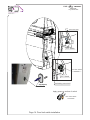
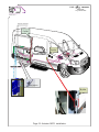
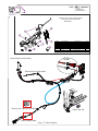
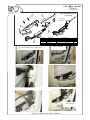
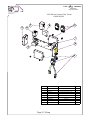
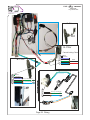
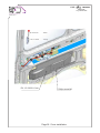
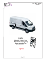
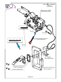
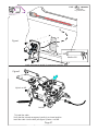
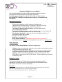
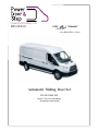
PowerDoorAndStep.com
888.928.8000
V363
TRANSIT
RWD/FWD
Long Wheel Base ,Jumbo
Automatic Sliding Door Set
PN: 015-3631-DL
Original Door latch mechanism
& operation with handles
V363
TRANSIT
RWD/FWD
Long Wheel Base
PowerDoorAndStep.com
888.928.8000
Door lock mechanism
C-pillar
Fuse 30A
B-pillar
2
AK105L
Lock Actuator
O.E. Door latch
Page 1. General view of ASD system.
V363
TRANSIT
RWD/FWD
Long Wheel Base
PowerDoorAndStep.com
888.928.8000
100
5
440
110
60
65
130
Page 2. Cutting and preparation.
V363
PowerDoorAndStep.com
888.928.8000
TRANSIT
RWD/FWD
Long Wheel Base
V363 Gear Motor Support Kit
160-36-310
2
7
5
4
3
1
5
5
6
ITEM NO.
PART NUMBER
DESCRIPTION
QTY.
1
111-36-310
V363 Gear Motor Support Right side
2
501-17-006
22x8.5x6 Spacer
3
3
600-12-080
Flat washer M6,thin DIN735
6
4
600-04-052
Spring Washer 6
6
5
632-06-016
Hex cap screw M6x15
6
601-06-006
7
107-11-004-1
Hex flange nut M6 DIN 6923
Idler Wheel
Page 3. Gear motor installation
1
7
4
1
V363
PowerDoorAndStep.com
888.928.8000
drill hole 16mm
for roller chain
Template
Original hole
C-Pillar
Page 4. Gear motor installation
TRANSIT
RWD/FWD
Long Wheel Base
V363
PowerDoorAndStep.com
888.928.8000
7
4
3
TRANSIT
RWD/FWD
Long Wheel Base
V363 Front Idler Kit
160-36-320
2
5
ITEM NO.
Hex cap screw M6x30
632-06-030
7
1
6
PART NUMBER
DESCRIPTION
QTY.
1
111-36-330
V363 Front Idler Kit
1
2
632-06-016
Hex cap screw M6x15
2
3
603-02-006
Rivet nut M6
3
4
600-12-080
Flat washer M6,thin DIN735
3
5
600-04-052
6
601-06-006
Hex flange nut M6 DIN 6923
2
7
632-06-020
Hex bolt M6x20 DIN933, 8.8
3
Spring Washer 6
3
V363 LHD Front idler upper holder
128-36-304
Hex nut M6 DIN 934 Cl.6
Sprocket ASSY
107-36-300
Hex nut M6 DIN 934 Cl.6
Idler wheel ASSY.
107-11-004-1
V363 LHD Front idler lower Support
128-36-305
Hex cap screw M6x30
632-06-030
Attach the front support to the gear-motor ASSY using
the bolts M6X16(2), and Nuts M6. Mark the
position of the holes in the back end of the mounting
bracket on the vehicle body.
Remove the front support.
Drill 33 holes
holes 9.5mm
9.5mm and
and install
install the
the threaded
threaded
Drill
inserts (QTY.
(QTY. 3)
3)
inserts
Page 5. Front Idler Installation.
V363
TRANSIT
RWD/FWD
Long Wheel Base
PowerDoorAndStep.com
888.928.8000
Chain Slide Strip Kit
160-36-330
5
0.
8
1
1.
50
4
230
38
17.5
2
3
230
ITEM NO.
PART NUMBER
1
134-36-301
2
601-06-006
3
134-36-302
4
613-06-020
DESCRIPTION
Chain Slide Strip (Transit)
Hex flange Nut M6
Chain Slide Strip front (Transit)
Socket flat head screw M6X20
QTY.
1
1
1
Washer 6
5
Step1
2
1
Use original threaded hole M6, fasten slip strips
using washer 6 and screw M6 . Press firmly both slip
strips to the track and mark the position for hole .
Surface of strip must be straight without waves.
Step2
drill
B-Pillar
Inside
Page 6. Chain Slide Strip Installation
V363
TRANSIT
RWD/FWD
Long Wheel Base
PowerDoorAndStep.com
888.928.8000
Rear Idler Kit
2
160-36-340
3
ITEM NO.
1
2
PART NUMBER
1
111-02-013-1
2
614-06-016
3
603-02-006
DESCRIPTION
Rear idler
Socket button head cap screw
M6X16
Rivet nut M6
Sprocket ASSY
107-36-300
Cut
Template
Drill hole 6.5mm
70
Drill hole 9.5mm and install the threaded
insert
70
Page 7. Rear Idler Installation.
Exploded/QTY.
1
2
1
V363
TRANSIT
RWD/FWD
Long Wheel Base
PowerDoorAndStep.com
888.928.8000
Roller chain route for installation
Electrical position
Page 8. Roller chain installation.
V363
TRANSIT
RWD/FWD
Long Wheel Base
PowerDoorAndStep.com
888.928.8000
Roller Chain Kit
160-36-350
4
2
3
5
ITEM NO.
PART NUMBER
DESCRIPTION
Exploded/QTY.
1
111-36-320
2
178-36-300
3
900-01-072
Chain bracket
Roller chain B05 L=3088 mm(192
Links )
Chain connecting link B05
4
134-36-303
V363 Slider
1
5
647-03-012
Screw M3x12
1
3
Page 9. Roller chain installation.
1
2
2
V363
PowerDoorAndStep.com
888.928.8000
Link 7
Link 1
Link 7
Page 10. Roller chain installation.
TRANSIT
RWD/FWD
Long Wheel Base
V363
PowerDoorAndStep.com
888.928.8000
Two stoppers rotate 180 degrees
Page 11.
TRANSIT
RWD/FWD
Long Wheel Base
V363
Plus wire installation
TRANSIT
RWD/FWD
Long Wheel Base
PowerDoorAndStep.com
888.928.8000
Fuse 30 A
O.E. Nut M6
“+” Battery
2
Signal Lamp
ACC
Operation Switch
AK105L
Chassis ground
Page 12. Wiring
V363
TRANSIT
RWD/FWD
Long Wheel Base
PowerDoorAndStep.com
888.928.8000
Electrical Accessories Kit
PN:160-36-300
Pneumatic safety strip
Operating Switch
PN;124-02-012-1
PN:113-65067
Signal Light
PN:124-10-069
Pneumatic Plastic Tube
c Door
Automati
Electric
Decal
PN:125-00-018
PN:113-26063
Rubber Tube
PN:113-06-067
L
AUTO COO
.
IND. LTD
SU
PE
R
Door Limit Switch
PN:124-00-039
GL
UE
100mm
Fast Glue
PN:144-30-007
Cable strap
PN:125-10-016
Cable strap
Pneumatic Safety Switch Assy
PN:160-10-042
150mm
Page 13. Electrical Accessories Kit
PN:125-10-014
V363
TRANSIT
RWD/FWD
Long Wheel Base
PowerDoorAndStep.com
888.928.8000
Drill 12mm hole
21mm
8mm
O.E. Switch
Door Limit Switch
O.E. Switch
Self drilling screw 8x1/2”
Cap (Spacer)
151-15-428
Apply grease on surface of switch
Door Limit Switch
124-00-039
Page 14. Door limit switch installation
V363
SU
PE
R
GL
UE
60 sec
15
R
PE
SU
Close
G
LU
E
29
Safety strip
Lock Actuator
Clean surface carefully with alcohol to insure
good contact of the pneumatic safety strip.
Transmitter
2
Safety Switch
Pneumatic Safety Strip
PN: 112-06-109
2
SU
PE
R
GL
UE
Rubber tube
Drill hole for rubber tube
Page 15. Pneumatic Safety Strip & Pneumatic Switch Installation
Left Sliding Door edge
PowerDoorAndStep.com
888.928.8000
TRANSIT
RWD/FWD
Long Wheel Base
V363
TRANSIT
RWD/FWD
Long Wheel Base
PowerDoorAndStep.com
888.928.8000
Door lock mechanism
C-pillar
B-pillar
2
Lock Actuator
B-pillar
O.E. Door latch
Page 16. Actuator ASSY. installation.
V363
TRANSIT
RWD/FWD
Long Wheel Base
PowerDoorAndStep.com
888.928.8000
ASD V363 Ford Transit _Original Door latch
mechanism & operation with handles
160-36-301
6
1
2
3
A
7
5
3
4
4
ITEM NO.
1
2
3
4
5
6
7
PART NUMBER
111-36-354
632-06-016
125-10-005
601-06-006
646-08-020
125-10-016
125-10-014
DESCRIPTION
Lock Actuator bracket ASSY.
Hex cap screw M6x15
Plastic clamp UC-2 3/8"
Hex flange nut M6 DIN 6923
Phillips screw 6x3/8"
Cable strap 100mm
Cable strap 100mm
Cut
Internal door handle cables
External door handle cable
Remove the cap from the cable
Return the cap
lower release cable
Page 17. Cable Diagram
QTY.
1
2
1
2
1
3
2
V363
TRANSIT
RWD/FWD
Long Wheel Base
PowerDoorAndStep.com
888.928.8000
Step 4
Step 3
Step1
Step 2
Step 2
Page 18. Rerouting Cable
V363
PowerDoorAndStep.com
888.928.8000
3
TRANSIT
RWD/FWD
Long Wheel Base
Lock Actuator ASSY.
4
111-36-354
Long sleeve 1
Short sleeve 2
1
5
ITEM NO.
PART NUMBER
1
128-36-354-2
2
Use this hole for O.E. cables clamp
2
3
4
5
110-01-006-10
110-01-006-Screw#4
128-36-309
128-15-203
DESCRIPTION
V363 Lock Actuator bracket
QTY.
1
Lock Actuator ASSY
V363: V408 Lock Actuator arm
Cables adapter
Use original hole
Drill 6mm hole
Page 19. Lock Actuator ASSY installation.
1
2
1
1
V363
PowerDoorAndStep.com
888.928.8000
Short Sleeve
Long Sleeve
Page 20. O.E. Cables installation.
TRANSIT
RWD/FWD
Long Wheel Base
V363
PowerDoorAndStep.com
888.928.8000
TRANSIT
RWD/FWD
Long Wheel Base
V363 Electric Harness Ford Transit
116-36-301-DL
7
3
6
5
9
1
2
8
s
vs
4
ITEM NO.
PART NUMBER
DESCRIPTION
QTY.
1
128-17-116
Bracket
1
2
124-10-504
VSS detector
1
3
124-38332
Control unit AK-105L V1.913
1
4
124-02-006
LD-007-1 - Remote control kit
1
5
124-02-906
6
124-13-902
7
124-00-032
Buzzer 12v
1
8
124-10-052
Socket terminal relay
1
9
R2A4-124
Relay
1
Page 21. Wiring
Remote Control Set
Latching relay 12v ASSY
1
1
V363
TRANSIT
RWD/FWD
Long Wheel Base
PowerDoorAndStep.com
888.928.8000
B- Pillar
cut
B- Pillar
Central locking Close
4
3
2
1
B- Pillar
EMPTY
Violet/White
Brown/Green
Blue/Gray
Sliding Door
4
3
2
1
EMPTY
Violet/White
Brown/Green Green (+) Lock Actuator
Blue/Gray
Blue (-) Lock Actuator
4
3
2
1
Page 22. Wiring
Green (+) Lock Actuator
Blue (-) Lock Actuator
Black
Red
V363
TRANSIT
RWD/FWD
Long Wheel Base
PowerDoorAndStep.com
888.928.8000
1
4
Under driver seat
Gray
DRIVING SPEED (VSS PULSE)
ACC+
Sliding door
Pressure switch
Lock Actuator
Front
Blue
Green
Red
White/Blue
4
8
3
7
6
2
1
VSS
Pulse Detector
Black
Black
O.E.Plug
Red
7
6
Red 1.5 mm
8
AK-105L(250)
9
Orange
10
30
1
Blue
87
2
86 85
3
Green
4
Black
5
Green
Red
Red
Green
latch Relay 12 V
Battery
12V
Blue
Green
5A
Blue
Green
Black
Red
2
Black
Red
Remote Control
(receiver)
1
Remote Control
(receiver)
Red 1.5 mm
Door limit swith
Green
Yellow
30
+ACC
Green
86
Signal Lamp
MOTOR 12V DC
87
Buzzer Black
Blue
Relay 12 V
Green
85
pin1
Connect to VSS
Green
CUT
White
D1
O.E.Plug (B-Pilar)
4 3 21
VSS
Black
4 3 21
OE wire brown/green from B-pilar plug
9
5
Con 5
2
OE wire Blue/gray from B-pilar plug
10
Gray
Black
Plug
Black
White
Black
Blue
White
Buzzer
Green
Blue
Plug
Operating switch
Internal micro switch
Black
Green
Orange
VSS (Vehicle speed sensor) connection
Red
30A
Page 23. Wiring diagram
19.02.15
V363
PowerDoorAndStep.com
888.928.8000
PN: 128-05-012
PN: 151-15-000
PN: 151-36-301-Cover
- Handle
- Housing
Phillips screw M6
Page 24. Cover installation.
TRANSIT
RWD/FWD
Long Wheel Base
V363
PowerDoorAndStep.com
888.928.8000
ASD
Automatic Sliding Door
External emergency
door opening kit
PN: 111-03-013
Option
Page 25
TRANSIT
RWD/FWD
Long Wheel Base
V363
PowerDoorAndStep.com
888.928.8000
TRANSIT
RWD/FWD
Long Wheel Base
Gear-motor ASSY.
Nut 6 ST
Nut 6 ST
Internal emergency handle
Emergency door KIT
PN: 111-03-013
Spring
Bracket
PN: 128-03-013A
Emergency door handle
PN: 111-03-0131
Emergency handle cover
PN: 151-03-131
Socket head M5X16
Page 26
V363
TRANSIT
RWD/FWD
Long Wheel Base
PowerDoorAndStep.com
888.928.8000
Figure1
cut
Sikaflex-221
Install the external handle for emergency opening door
Figure2
Nylock nut M5
Nut M6
To install the cable:
Verify that the Internal emergency handle is on closed position.
Insert the cable into the hole (see figure 2) fasten nuts M6
Page 27
V363
TRANSIT
RWD/FWD
Long Wheel Base
PowerDoorAndStep.com
888.928.8000
1
Insert the emergency handle 1 . Move the handle to right
for electrical operating
10
mm
Install the cable
Clamping lug
Nylock Nut M5
Spring
Washer 4
Washer 4
Bolt M4X8
Page 28
V363
TRANSIT
RWD/FWD
Long Wheel Base
PowerDoorAndStep.com
888.928.8000
Pneumatic rubber tube
PN:160-10-042
Pneumatic Switch
PN:122-10-047
Sensitivity adjustment
Increase Sens
Decrease Sens
Page 29
Hex key
N 4mm
V363
TRANSIT
RWD/FWD
Long Wheel Base
PowerDoorAndStep.com
888.928.8000
ASD: Basic Troubleshooting
1. Door does not function.
• Check main fuse.
• Check connections of power terminals to the control unit, motor and operating switch.
• Check Control units AK-105L
• Check motor.
2. Door does not operate upon commencing the closing mode or when reaching the fully
closed position it reverses.
• Check the safety pneumatic pressure tube; disconnect the plugs of pressure
switch and close the door.
• If the issue is not solved, try to regulate the sensitivity of the pressure switch.
• Check safety switch.
• Reset the system by extracting the fuse and returning it to its place.
• Check control unit – AK105.
3.
Door does not close completely.
• Check voltage of battery, if low, start the engine.
4.
Door does not open, although the electrical motor is engaged.
• Check position of the locker unit, which annuls the OEM locking system of the door.
5. Door does not automatically reverse when encountering an obstruction during
the closing mode.
• Check safety pneumatic switch.
• Check pressure tube & switch.
• Check control unit.
6. Noise from the door's chain during opening and or closing modes.
• Check installation and alignment of all wheel supports, front and rear,
as well as the gear motor support.
• Very loose chain may also jump over and cause damage to the sprocket’s main motor.
• Check chain tension and if needed shorten it by removing one or two “ links”.
7. Remote control unit does not function.
• Check connection of power terminals.
• Check battery of the key unit transmitter.
If issue still persists, replace the remote control receiver and the two transmitters
8. If equipped with VSS, the door operates although the vehicle is in motion over 5Km/h.
• Check connections to the VSS unit.
• Check VSS unit.
9. Buzzer does not operate during the closing mode.
• Check buzzer or replace it.
Please note:
The system performs automatic reset after the ASD has been disconnected from the power
either when replacing the fuse or by disconnecting the Battery.
The system resets itself within two minutes. Please be patient.
Page 30
V363
TRANSIT
RWD/FWD
Long Wheel Base
PowerDoorAndStep.com
888.928.8000
Automatic Sliding Door user’s Manual.
The Automatic Sliding Door system (ASD) manufactured by Auto Cool Ltd
conforms with the requirements of the European regulations.
The ASD is approved by the German TUV in Munich, it complies with the
EEC DIRECTIVE 72/245EC and obtained the certificate of compliance No
2004/104/EC.
Operation Instructions
The door is operated by a switch located on the dashboard:
To open–press the switch shortly, door opens to the end of its range.
To close - press the switch shortly, door closes and locks.
To change its direction while in motion - press the switch shortly,
the door will change direction.
To control the opening range – continuous pressure on the control switch will
set the door in motion upon its release, the door will stop.
Visual status indications – when the vehicle’s main ignition switch is “on”,
the indicator control light is visible.
Dim light – the door is closed.
Bright light – the door is open.
Audio status indicators – independently of the vehicle’s main switch –
the vehicle’s buzzer is always functioning whenever the door is in closing motion.
Safety measures
The system includes safety features to protect the passengers.
Closing – when encountering an obstruction, the controller automatically reverses
the door direction to open all the way .
In addition, a pneumatic switch is attached to the front side of door pillar, which
upon sensing pressure performs the same function and retracts immediately.
Opening - when encountering an obstruction, the controller stops the door.
ASD system is connected to the OE VSS device. The door operates only at speed
of less than 5 km/h.
Emergency facility
The system has inside and outside (optional) emergency releasing handle.
Operating one of them will result in disconnecting the ASD mechanism device
and the door will function manually immediately.
Please note:
The system performs automatic reset after the ASD has been disconnected from the power
either when replacing the fuse or by disconnecting the Battery.
The system resets itself within two minutes. Please be patient.
Page 31
V363
PowerDoorAndStep.com
888.928.8000
TRANSIT
RWD/FWD
Long Wheel Base
Tools required for installation
ASD. AAD. STEP. ATG
Air Reciprocating Saw
Saw BLades
or
High speed threaded insert tool
or
13mm Pneumatic Drill
Heavy duty hand tool for field
and low volume production use
or
Air Die Grinder
Small hand tool for
. prototype work and repairs
Hand holding battery-powered electric drill
Soldering-iron
Flashlight or drop light
Pencil or marker
Safety Glasses
Page 32.
Masking Tape 50MM
V363
TRANSIT
RWD/FWD
Long Wheel Base
90
PowerDoorAndStep.com
888.928.8000
Straight Flute HSS Step Drill
diameter 4-30mm
Drill Point Countersinks
Straight Shank Twist Drill
diameter 4mm / 5mm / 6mm/ 6.5mm / 7mm / 9.5mm 12mm
T-Handle Set
Heavy Duty Snap Blade Knives
Hand Files
Wire Stripper/Crimper
Locking plier
Combination Wrench Set Metric
Plier Set
1/4" Drive Socket Set metric
Screwdriver Set
Page 33.