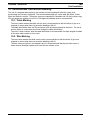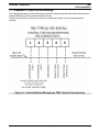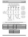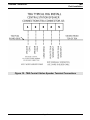
1
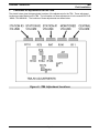
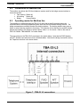
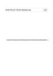
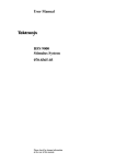
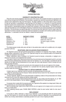
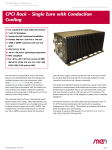
Industrial Communications Worldwide
Talk Back Amplifier
Field Installation
Information
P007631 Rev. A 140818 8/18/2014 10:43 AM
Ph: 403.258.3100 \ email:[email protected] \ www.guardiantelecom.com
Guardian Telecom Inc.
TBA
Field Installation
Contents
1.
Purpose ............................................................................................ 4
2.
Scope ............................................................................................... 4
3.
Identification of equipment ................................................................ 4
3.1.
TBA Model Numbering ............................................................ 4
3.2.
TBA Front Panel ...................................................................... 5
3.3.
TBA Rear Panel ...................................................................... 5
3.4.
TBA Enclosure Inside .............................................................. 6
4.
System Overview.............................................................................. 7
4.1.
Central Station......................................................................... 7
4.2.
Monitored Station .................................................................... 7
4.3.
Stations #1, #2 and #3............................................................. 7
4.4.
PTT Actions............................................................................. 8
4.5.
Alert or Go-Ahead Tone .......................................................... 8
4.6.
Applications on Drilling Rigs .................................................... 8
4.7.
Applications on Shipboard ....................................................... 8
5.
Application Restrictions .................................................................... 9
6.
Installation Environment ................................................................... 9
6.1.
Oil rig Installations ................................................................... 9
6.2.
Marine Installations ................................................................. 9
6.3.
Building Installations ................................................................ 9
7.
8.
Locations of adjustments for the TBA ..............................................10
Connections for Oil Rigs ..................................................................11
8.1.
Operating modes for Oil Rigs .................................................11
8.2.
Connections for Maritime Use ................................................12
8.3.
Operating modes for Maritime Use .........................................12
9. Connections of Cables.....................................................................13
9.1.
Connections within the TBA enclosure ...................................13
9.2.
Connections on Speakers ......................................................13
9.3.
Connections with cable connectors ........................................13
9.4.
Grounding of cable shields .....................................................13
10. Recommended Cable and Wire Marking .........................................14
10.1. Cable Marking ........................................................................14
10.2. Wire Marking ..........................................................................14
11. Diagrams of Cable and Wire Marking ..............................................15
12. Diagrams of Connections for TBA-41 with Selector Switch ..............24
13. Warranty ..........................................................................................26
14. Disclaimer........................................................................................26
15. Warning ...........................................................................................26
16. Service Telephone Number 1-800-363-8010 ..................................26
17. Feedback.........................................................................................26
18. Guardian Product Return .................................................................27
Page 2
Guardian Telecom Inc.
TBA
Field Installation
Figures
Figure 1 - Table of TBA Models ............................................................... 4
Figure 2 - TBA-41 Front Panel ................................................................. 5
Figure 3 - TBA-41 Rear Panel ................................................................. 5
Figure 4 - TBA-51 Enclosure Inside Front ................................................ 6
Figure 5 - TBA-51 Enclosure Inside Rear ................................................ 6
Figure 6 - TBA Adjustment Locations .....................................................10
Figure 7 - TBA-33 L3 connections ..........................................................12
Figure 8 - Central Station Microphone TBA Terminal Connections .........15
Figure 9 - Central Station Microphone Device Connections ....................16
Figure 10 - TBA Central Station Speaker Terminal Connections ............17
Figure 11 - Central Station Speaker Device Connections .......................18
Figure 12 - TBA Station Terminal Connections .......................................19
Figure 13 - Monitored Station Device Connections .................................20
Figure 14 - TBA Station #1 Terminal Connections ..................................21
Figure 15 - TBA Station #2 Device Connections .....................................22
Figure 16 - TBA Station #3 Device Connections .....................................23
Figure 17 - TBA-41 Oil Rig PTT Additional Connections .........................24
Figure 18 - TBA-41 Oil Rig PTT Switch Wiring .......................................25
Acronyms:
TBA
PWB
PWBA
AC
DC
KHz
Hz
SW
Talk Back Amplifier
Printed Wiring Board
Printed Wiring Board Assembly
Alternating Current
Direct Current
Thousand Hertz
Cycles per second
Switch
Page 3
Guardian Telecom Inc.
1.
TBA
Field Installation
Purpose
As the TBA may be installed and have the installation customized for various applications, the
designers and installers of the custom applications need to document their installations. This document
is provided to assist and document the electrical installation of a Talk Back Amplifier (TBA) as produced
by Guardian Telecom Inc.
2.
Scope
The Talk Back Amplifier (TBA) installation information will consist of connections to the TBA unit to
external speakers, microphones and switches.
The type of inter-connection cable, and the wire colours within the cable are recommended. The actual
cable and wire colours used can be documented using this manual.
The addition of selector switches for a typical Oil Rig Installation with a TBA-41 is also outlined.
This manual does not cover the operation information consisting of adjustment of potentiometers and
power supply requirements for the TBA unit. The speaker and microphone sensitivity that relates to the
TBA operation is not covered by this manual. The manual P007143 “MANL- TBA MANUAL“ can be
used for the selection of peripherals and adjustment for system levels.
3.
Identification of equipment
There are several models of Guardian Talk Back Amplifiers (TBA). The Printed Wiring Board Assembly
(PWBA) in the TBA will support up to five speaker outputs; therefore the listing of speaker connections
goes from five speaker outputs to two speaker outputs.
3.1.
TBA Model Numbering
The table below uses “CEN” for Central Station, “MON” for Monitored Station and #1 to #3 for
Stations #1 to #3. The “X” in a square indicates that the speaker amplifier is populated on the
PWBA. The “L” indicates low impedance and the “H” indicates high impedance.
Figure 1 - Table of TBA Models
Page 4
Guardian Telecom Inc.
3.2.
TBA
Field Installation
TBA Front Panel
The TBA Front Panel of the enclosure has from two to five volume controls and a power indicator.
The power indicator shows the presence of AC power, and is a green illumination if AC is present.
The volume controls are labeled for the Station being controlled. Clockwise rotation gives more
volume, the volume controls have numbers from1 to 10 to assist in setting repeatability.
Figure 2 - TBA-41 Front Panel
3.3.
TBA Rear Panel
The TBA Rear Panel of the enclosure has from two to five cable entries, an AC power connector,
an AC fuse and a Power ON/OFF switch.
The AC power connector is a standard connector for AC supplies. The AC fuse is a 1 amp slow
blow 250 volt fuse of 1.25” long and 0.25” diameter.
Buss fuse type MDL 1A is supplied with the TBA.
The POWER ON/OFF switch is a rocker switch; pushing the switch upwards turns on the TBA.
Figure 3 - TBA-41 Rear Panel
Page 5
Guardian Telecom Inc.
3.4.
TBA
Field Installation
TBA Enclosure Inside
The photos below show the TBA-50 with the top cover removed.
Figure 4 - TBA-51 Enclosure Inside Front
The customer will access the interior of the TBA by removing the top panel.
The wiring connections of all of the TBAs are done to the green terminal blocks on the PWBA.
The TBA-41 may have a set of terminal blocks added to allow an external selector switch.
Figure 5 - TBA-51 Enclosure Inside Rear
The entry of the cables into the TBA housing is through the cable glands located on the back panel
of the TBA housing.
The above figure shows the cable glands without cables entering.
Page 6
Guardian Telecom Inc.
4.
TBA
Field Installation
System Overview
The Talk Back Amplifier (TBA) is so named because of the ability for the user to talk back to the
speakers instead of using a separate microphone to talk back.
The model TBA is an intercom system designed for use in situations where frequent communications
between two or more stations are required.
The TBA system utilizes speakers in two modes:
• as a speaker output to broadcast audio messages from other stations
• as an audio microphone to pick up audio messages.
4.1.
Central Station
The Central Station speaker normally outputs audio coming from the Monitored Station.
The audio from the Monitored Station or Stations #1, #2 or #3 with their PTT depressed, will be
output on the Central Station speaker.
To output audio the Central Station user presses the Press to Talk (PTT) switch. The Central
Station PTT switch is normally mounted on the microphone housing, but it may be a foot switch.
The Central station is different from the other stations in that it has a separate microphone input as
well as a speaker output. The Central Station speaker also has a low level “sidetone” audio from
the speaker to allow the user to hear that the Central Station audio output is working.
The Central Station console consists of a (goose neck) dynamic microphone and a hand switch or
pedal switch for PTT. The Central Station has the highest priority in using PTT. When the Central
Station PTT switch is engaged (depressed) the TBA puts a low level audio onto the Central Station
speaker. This low level is to prevent acoustical feedback. The other speakers in the system are set
to the speaker mode and output audio coming from the Central Station.
4.2.
Monitored Station
The Monitored Station is different from the other stations in that it will continuously send the audio
heard at its speaker to the other stations when no Press to Talk (PTT) switch in the TBA is
depressed. The Central Station and up to three stations normally output audio coming from the
Monitored Station to their speakers.
The PTT switch on the Monitored Station is used only as a “Ringing” or Alert Tone activation.
Pressing the Monitored Station PTT will stop the audio output from the Monitored Station and put a
“Ringing” tone onto the Central Station, Monitored Station and the other stations’ speakers.
The Monitored Station speaker will output the audio coming from another station if the other station
presses a PTT switch. When the Monitored Station speaker is outputting audio it does not send
audio to the other stations. The Monitored Station speaker will change from a microphone input
into a speaker output when the Central Station or another station has the PTT switch pressed.
4.3.
Stations #1, #2 and #3
The Stations #1, #2 and #3 have a speaker and a PTT switch. The audio from the Monitored
Station or any other station with a PTT depressed will be output on that station’s speaker. When
the station’s PTT switch is depressed the station will output audio to the other stations. When the
speaker is outputting audio it does not receive audio from the other stations.
Page 7
Guardian Telecom Inc.
4.4.
TBA
Field Installation
PTT Actions
The Central Station Push to Talk (PTT) switch has the highest priority in using PTT.
When the PTT is pressed on the Monitored or Stations #1, #2 or #3 the stations are a first-come
first-served basis for PTT.
When the PTT switch on the Monitored Station is pressed the other speakers on the system will
output a “ringing” tone for as long as the PTT is pressed.
When the PTT switch on the Central Station, Stations #1, #2 or #3 is pressed the system will use
the speaker on that station to generate audio for the other station speakers.
4.5.
Alert or Go-Ahead Tone
The Talk Back Amplifier (TBA) has a tone generator that sounds similar to a telephone ringing.
This dual tone (“Ringing”) is generated for two purposes:
• Alert
• Go-Ahead
The Alert Tone or “Ringing” is caused by the Monitored Station pushing the Push to Talk (PTT)
switch.
The Go-Ahead short “Ringing” is a 0.1 second long sound burst that indicates to the users that a
PTT switch has just been released on the Central Station or Station #1, #2 or #3. This Go-Ahead
indicates that the other station has ceased pressing the PTT switch and that normal operation can
be resumed. When this post announcement short “Ringing” tone is heard it confirms to the listener
that the system is in the receive mode.
Jumper JP1 on the Printed Circuit Board Assembly (PCBA) is a switch to allow the injection of the
post PTT Go-Ahead or short “Ringing” tone. Moving JP1 to the bottom set of terminals will disable
the Go-Ahead or short “Ringing” tone.
4.6.
Applications on Drilling Rigs
In drilling rig applications the TBA normally consists of:
• Central Station at the doghouse with a speaker and microphone
• Monitored Station at the monkey board
• Station #1, #2 and #3 as needed.
The monkey board or racking board for the derrick man is up on the drilling rig tower, and the
derrick man’s instructions to the dog house (driller’s communication shack) should be continuously
monitored.
There is a version of the TBA-41 that has an additional set of terminal blocks installed to allow the
use of a selector switch. The TBA-41 custom system was setup for optimal performance based on
simulated noise at site. Minor adjustments to the talkback input level as well as possibly the derrick
speaker output and the doghouse speaker volume level may have to be made when the rig moves to
location and is operational.
4.7.
Applications on Shipboard
Audio monitoring of the wheelhouse or control station can be used to inform the engine room and
other stations of the actions needed to be performed. In this way commands for ship operation can
be communicated without delay by the ship operator simply speaking.
The telephone intercom on board the ship is connected to a special impedance of the Central
Station made for the 600 Ohm telephone system. A PTT from the telephone line is used to activate
the output to the talk back speakers both FORE and AFT. After the PTT the FORE and AFT can
reply back to the telephone system by talking to the speakers. The period for the FORE and AFT
stations to talk back after a PTT is received from the telephone interface is selected by a jumper on
Monitored Station PTT for 1 minute, or a jumper on Station #1 PTT for 10 minutes.
Page 8
Guardian Telecom Inc.
5.
TBA
Field Installation
Application Restrictions
The Talk Back Amplifier (TBA) PWBA enclosure is not approved for use in hazardous areas.
The Central Station console microphone (as supplied) is not approved for use in hazardous areas. A
microphone may be used in hazardous areas if it is connected through an approved intrinsically safe barrier.
The Push to Talk (PTT) switches may be of a suitable rating for use in hazardous areas, or connected
through an approved intrinsically safe barrier.
Any application of equipment into a hazardous area must be approved by the appropriate authority.
The speakers used may be of a suitable rating for use in hazardous areas. The speakers used with the
system may or may not be approved, check the labels on the speakers for ratings.
Follow all local codes and requirements when installing the TBA Intercom System.
The TBA does not have a weatherproof or drip-proof rating, and is not protected for prolonged
exposure to high humidity and salt fog.
6.
Installation Environment
The Talk Back Amplifier (TBA) enclosure is to be mounted in an indoor environment, and located away
from sources of electrical noise for minimum system noise.
The wiring of the TBA to the microphones and speakers is to be done using cable that is both shielded
and rated for the environment.
The use of connectors or junction boxes for the cables should be rated for the environment.
6.1.
Oil rig Installations
The Oil Rigs addressed are for land use, but marine applications can be supported. As the Oil Rigs
are located without a surrounding weatherproof building, all connections and cables used must be
for outdoor use. The selection of the cable for temperature extremes should be done to ensure the
installation and maintenance can be done at any of the expected temperatures.
The use of junction boxes for disassembly of the oil rigs for movement can be done using junction
boxes with connectors. The junction boxes, connectors and wire for these should be chosen to
allow the worst case environment. A minimum rating of IP4 for the enclosures is needed, and IP6
should be used for enclosures that are used in a marine environment. If oil or solvents are to be
used around these items, the appropriate IP rating and chemical resistance should be used.
The connectors used should be watertight and fully seal the cable wires and shield for water
ingress. The recommended type of connector is a D38999 type, typically called “MIL STD”. The
use of the cable and connector fittings to make the fittings fully watertight should be done. The
cable sheath should be sealed to the connector strain relief. The cable should be physically
retained in the connector so that it does not allow either wire or shields to be strained or have water
ingress. The use of additional heat shrink tubing over the rubber cable strain relief and body of the
connector will provide both mechanical and weatherproofing improvements.
6.2.
Marine Installations
The use of the TBA shipboard for the communications from the bridge to stations is one of the
applications. The use of cables and connectors in an unprotected salt water environment is an
extreme application. The speakers used for the stations must be at least IP6. The cables and
connectors should be protected from accidental punctures or damage as well as allow for drainage
after a short submersion.
The TBA has been designed to have good EMC characteristics, and has EMC levels compatible for
shipboard use in proximity to radio communications. The locating of cables or speakers in areas of
radar transmitters may cause problems.
6.3.
Building Installations
The TBA can be used as an intercom system. Models TBA-21, TBA-31, TBA-41 and TBA-22 are
able to be used for locations where a speaker and push to talk switch are able to allow
communications to the other points.
Page 9
Guardian Telecom Inc.
7.
TBA
Field Installation
Locations of adjustments for the TBA
The sketch below gives the approximate locations of the adjustments for the TBA. These adjustment
locations are also labeled on the TBA. The information on these adjustments is in the manual P007143
“MANL- TBA MANUAL“ The locations of these adjustments are shown below.
Figure 6 - TBA Adjustment Locations
Page 10
Guardian Telecom Inc.
8.
TBA
Field Installation
Connections for Oil Rigs
The Oil Rig installations is referred to as Rigs.
The typical Rig installation has the following locations connected:
• Drill Floor
Monitored Station
• Derrick
Station #1
• Dog House
Central Station
8.1.
Operating modes for Oil Rigs
The Drill Floor is usually monitored continually by the Dog House. The button on the Drill Floor
usually creates a “ring tone” to the others.
The Dog House can talk to the Drill Floor and Derrick using a microphone and “Push To Talk” (PTT)
button.
The Derrick can talk to both the Dog House and the Drill Floor by pressing a PTT button.
Refer to the manual P007143 “MANL- TBA MANUAL“ for further details.
The connection of the Dog House so that the sound from the monitored station is always active may
cause excessive noise. An additional selector switch for the Dog House can be implemented to
give:
OFF
Not transmitting or receiving from the Dog House
TALK
Dog House is transmitting
DRILL FLOOR
Dog House is monitoring the Drill Floor
DERRICK
Dog House is monitoring the Derrick
The connections of the selector switch to allow these operating modes is shown in a figure below.
This is done by the 4 way switch connecting across the PTT switch for Dog House, Drill Floor or
Derrick. See the section on TBA-41 Oil Rig Connections.
The PTT for each station is paralleled by the 4 position switch. When the switch is in the position
for the action, the PTT line is connected. When the PTT line is not jumpered by the selector switch,
the PTT operates normally, except that the priority of the PTT is Doghouse, then Drill Floor. If the
Drill Floor activates PTT when the Doghouse is selecteed, there will be no action.
The PTT for the Derrick goes to the PTT on the Monitored input, which will create a “ringing” on the
speakers. The selection of DERRICK on the selector switch by the operator in the Doghouse will
cause the Derrick to change from speaker mode to microphone mode.
For the TBA-41 Oil Rig installations, the typical settings are:
Speaker Volume Levels and Tap Settings
Drill Floor Speakers - 7.5 Watts (Tap Setting) Level 7 (Volume Control)
Derrick Speaker - 7.5 Watts (Tap Setting)
Level 7 (Volume Control)
Doghouse Speaker - 4 Watts (Tap Setting)
Level 10 (Volume Control)
TBA-41 Internal Settings
Microphone Volume
R8 on the PCBA set to 11 o’clock position
(mid-range)
Talkback Input level
R25 on the PCBA set to 2 o’clock position
(low end) “based on noise from fan”.
Doghouse Speaker Attenuation
R31 on the PCBA set to 6 o’clock (mid-range)
Page 11
Guardian Telecom Inc.
8.2.
TBA
Field Installation
Connections for Maritime Use
The maritime use allows the 600 ohm telephone system used for the bridge communications to
communicate with:
• Fore docking Station #1
• Aft docking
Station #2
• Bridge
Central Station
8.3.
Operating modes for Maritime Use
The operation on shipboard using the TBA-33 L3 which has a specific program allows the
communication to the bridge telephone system from both the fore and aft docking stations. The
bridge commands are normally heard at the docking stations. The docking stations may press a
button to select that they transmit to the bridge. The selection of time that the fore and aft docking
stations send audio to the bridge is another option, either 1 or 10 minutes. Refer to the manual
P007143 “MANL- TBA MANUAL“ for further details.
The connections on the TBA-33-L3 are shown in the sketch below. Note that the FWD Speaker
and AFT Speaker connections are 2 wire shielded cables. Note that the bridge connections are by
the Telephone Interface in the sketch below.
Figure 7 - TBA-33 L3 connections
Page 12
Guardian Telecom Inc.
9.
TBA
Field Installation
Connections of Cables
The cable entry seals of the TBA enclosure will fit a normal 4 wire shielded cable.
The shielded cable should be at least 80% shield coverage, and the use of added foil coverage will help
with radio interference reduction. The following diagrams show the connections of the cables, and the
recommended wire colours. If different colours are used on the wires, the user should note these in a
drawing for maintenance and repair functions.
The cable may have wires as small as 26 AWG, however 22 AWG is recommeneded. The use of
stranded copper wire with a minimu of 7 strands is also recommended. The use of polypropelene
insulation is allowable, and the use of teflon insullation is recommended for wet or marine
environments.
9.1.
Connections within the TBA enclosure
The connections of the cable to within TBA enclosure is by terminal blocks, and the TBA enclosure
should be in a dry indoor environment. The use of ferrules will allow easier installation and
troubleshooting. The entry points into the TBA enclosure are supplied with cable glands. The
strain relief of the cables at the cable gland and about a 3” slack in the cable inside the enclousre is
recommended.
9.2.
Connections on Speakers
The speakers for the TBA system are normally outside and require at least IP4. The entry points
into the speaker enclosure should have cable glands. The strain relief of the cables at the cable
gland and about a 3” slack in the cable inside the enclousre is recommended. The cable shield
should be only non-sheathed for the with aobut 1” back from the terminals. The cable shield should
be sealed so that the entry of water into the cable is prevented, even if the speaker enclosure is
supposed to be watertight. The use of self vulcanizing rubber tape or heat shrink tubing with glue
on the inside is recommended to ensure waterproofing. The entry of water into the cable shield will
allow both corrosion of the cable shield and wetting of the shielded wires with will cause system
degredation or failure.
The electrical connection of the speaker wires must be either soldered or with a gas tight clamped
fitting. The loose twisting of the wires together without a clamp will cause failures.
9.3.
Connections with cable connectors
The use of connectors to allow equipment disassembly is normally done. The connectors can be
either male-felmale inline D38999 or equivalent, or with waterproof connections to a junction box.
The wires must be connected by soldering or clamped gas tight contacts. The shields must be
sealed. The use of self vulcanizing rubber tape or heat shrink tubing with glue on the inside is
recommended to ensure waterproofing. The entry of water into the cable shield will allow both
corrosion of the cable shield and wetting of the shielded wires with will cause system degredation or
failure.
9.4.
Grounding of cable shields
The cable shields must contact the safety ground only at the TBA enclosure for the least system
noise. The use of a terminal box with the shield connected to the metal of the terminal box will
cause system noise from the safety ground electrical noise. The use of plastic enclosures for the
terminal box may allow the shield to be isolated. Note that dirt and contaminants on the outside of
a plastic terminal box will become conductive when wet, and system noise may result. The
connection of the cable shield from the TBA enclosure to the final point should be ensured to have
the cable shield operate correctly for electrical interference.
Page 13
Guardian Telecom Inc.
TBA
Field Installation
10. Recommended Cable and Wire Marking
The use of a standard cable marking, wire colours and wire marking will allow the sytem to be
documented and correctly configured. The recommended cable is a 4 wire cable with White, Green,
Black and Red wire colours. These wire colours are standard for Canadian and US wiring codes using
220 volt appliances, and the use of UL or CSA approved shielded wires is recommended.
10.1. Cable Marking
The use of cable markers that slide onto the wire is recommended so that the failure of glue on a
wrapped on wire marker does not cause the labelling to fall off.
The cable identification from the TBA enclosure to the end device should be the same. The use of
junction boxes or connections should not change the cable identification.
The use of “dash numbers” after the cable idenfication is recommended if multiple lengths of cables
of the same cable number is to be used.
10.2. Wire Marking
The use of wire markers that slide onto the wire is recommended so that the failure of glue on a
wrapped on wire marker does not cause the labelling to fall off.
The wire colours are given in the diagrams and it is recommeneded that they be either used, or
create a set of drawings marked-up to show the wire colours in use.
Page 14
Guardian Telecom Inc.
TBA
Field Installation
11. Diagrams of Cable and Wire Marking
The following diagrams give the cable marking and wire marking such that each cable and each wire is
marked differently so that it can be identified correctly.
Follow the instructions in the previous section on marking the cables and wires with permanent
labelling.
Figure 8 - Central Station Microphone TBA Terminal Connections
Page 15
Guardian Telecom Inc.
TBA
Field Installation
Figure 9 - Central Station Microphone Device Connections
The table below can be used to document the installation for future reference.
CABLE USED
LENGTH
NOTES ON INSTALLATION AND
OF CABLE CONNECTORS USED
TBA
JUNCTION BOX
MICROPHONE
SWITCH
If the cable has different colour wires note the wire colour used.
MM1
MM2
MM4
MM5
Page 16
Guardian Telecom Inc.
TBA
Field Installation
Figure 10 - TBA Central Station Speaker Terminal Connections
Page 17
Guardian Telecom Inc.
TBA
Field Installation
Figure 11 - Central Station Speaker Device Connections
The table below can be used to document the installation for future reference.
CABLE USED
LENGTH
NOTES ON INSTALLATION AND
OF CABLE CONNECTORS USED
TBA
JUNCTION BOX
SPEAKER
If the cable has different colour wires note the wire colour used.
MS1
MS2
Page 18
Guardian Telecom Inc.
TBA
Field Installation
Figure 12 - TBA Station Terminal Connections
Page 19
Guardian Telecom Inc.
TBA
Field Installation
Figure 13 - Monitored Station Device Connections
The table below can be used to document the installation for future reference.
CABLE USED
LENGTH
NOTES ON INSTALLATION AND
OF CABLE CONNECTORS USED
TBA
JUNCTION BOX
SPEAKER & SW
If the cable has different colour wires note the wire colour used.
MN1
MN2
MN4
MN5
Page 20
Guardian Telecom Inc.
TBA
Field Installation
Figure 14 - TBA Station #1 Terminal Connections
The table below can be used to document the installation for future reference.
CABLE USED
LENGTH
NOTES ON INSTALLATION AND
OF CABLE CONNECTORS USED
TBA
JUNCTION BOX
SPEAKER & SW
If the cable has different colour wires note the wire colour used.
1S1
1S2
1S4
1S5
Page 21
Guardian Telecom Inc.
TBA
Field Installation
Figure 15 - TBA Station #2 Device Connections
The table below can be used to document the installation for future reference.
CABLE USED
LENGTH
NOTES ON INSTALLATION AND
OF CABLE CONNECTORS USED
TBA
JUNCTION BOX
SPEAKER & SW
If the cable has different colour wires note the wire colour used.
2S1
2S2
2S4
2S5
Page 22
Guardian Telecom Inc.
TBA
Field Installation
Figure 16 - TBA Station #3 Device Connections
The table below can be used to document the installation for future reference.
CABLE USED
LENGTH
NOTES ON INSTALLATION AND
OF CABLE CONNECTORS USED
TBA
JUNCTION BOX
SPEAKER & SW
If the cable has different colour wires note the wire colour used.
3S1
3S2
3S4
3S5
Page 23
Guardian Telecom Inc.
TBA
Field Installation
12. Diagrams of Connections for TBA-41 with Selector Switch
The continuous monitoring of the drill floor or the monkeyboard can cause extra noise in the doghouse
when drilling operations are not underway. The ability to silence these inputs is done by the addition of
a 4 way selector switch that is located in the doghouse. See the section above titled “Operating Modes
for Oil Rigs” for the naming of each of the switch positions.
The following diagrams give the connectiions for the cable and wires to the terminal block connections
on the TBA-41 when a “silencing switch” is installed. The drawings for this installation are in
OA-TBA41-ORS.
The positions of the switch are:
• OFF
Not transmitting or receiving from the Dog House
• TALK
Dog House is transmitting
• DRILL FLOOR
Dog House is monitoring the Drill Floor
• DERRICK
Dog House is monitoring the Derrick
Figure 17 - TBA-41 Oil Rig PTT Additional Connections
Page 24
Guardian Telecom Inc.
TBA
Field Installation
Figure 18 - TBA-41 Oil Rig PTT Switch Wiring
As the connection of the PTT on the Derrick (sometimes called the Monkeyboard) goes to the
Monitored PTT input, the action of the Derrick PTT is non standard.
Note that in the above figure the input to J11 Derrick PTT is only from the selector switch.
The PTT switch located on the Derrick (called PTT ON DERRICK) goes to terminals 10 and 11. The
activation of the PTT switch on the Derrick will cause the speakers to output a ringing, and it will not
activate the Derrick to change from speaker mode to microphone mode.
The selection of DERRICK on the selector switch by the operator in the Doghouse will cause the
Derrick to change from speaker mode to microphone mode.
Page 25
Guardian Telecom Inc.
TBA
Field Installation
13. Warranty
Guardian Telecom warrants your product to be free of defects in material and workmanship for a period
of one year. Guardian Telecom will repair or replace any defective unit that is under warranty free of
charge.
This warranty is null and void if any non-authorized modifications have been made to this product, or if
it has been subjected to misuse, neglect, or accident. This warranty covers bench repairs only; such
repairs must be made at Guardian Telecom or an authorized service depot. Guardian Telecom is not
responsible for costs incurred for on-site service calls, freight, or brokerage.
A return authorization must be obtained prior to warranty claims or repairs.
14. Disclaimer
The products covered by this manual are designed for use in Industrial Environments and/or Hazardous
Locations. Due to the range of possible applications for these instruments the manufacturer will not be
responsible for damages or losses of any kind suffered as a result of the use of this product, including
consequential damages.
15. Warning
This device may be opened and reassembled by qualified personnel only, for the purposes of installing
the product, making adjustments and replacing components, following the instructions in the product
manual.
High voltages may be present in this product when connected to system wiring.
16. Service Telephone Number 1-800-363-8010
Guardian Telecom provides a customer service telephone number which is toll-free within North
America. If you need assistance when installing or operating this product, please call the toll-free
telephone number between regular business hours (8:00AM-5:00PM), Mountain Standard Time. If you
are calling outside of regular business hours, please leave a detailed message, and a member of
Guardian Telecom’s Service Department will return your call as soon as possible. If your product
requires service, Guardian personnel will supply you with an RMA (return materials authorization)
number over the telephone or through our web site product return page. This number must be included
with your return address and the name of the person to contact.
Guardian Telecom Inc.
Toll-free 1-800-363-8010
Ph. (403) 258-3100
Fax. (403) 253-4967
www.guardiantelecom.com
17. Feedback
Guardian Telecom continually strives to make reliable, durable, and easy to use products. If you, as an
installer or user of our equipment, have any suggestions for improvements to this or any of our products
or documents, including this manual, we would appreciate hearing from you.
Page 26
Guardian Telecom Inc.
TBA
Field Installation
18. Guardian Product Return
Guardian products have been quality tested and are in full working order when
shipped from the factory, given the rugged nature of these products shipping is not
expected to damage a unit. In the unlikely event of a malfunction Guardian follows the
three step procedure below.
Step I - On-Site Correction
The most common source of difficulties with a new product is improper installation in one of
two ways: incorrect wiring connections or connection to an incorrect power source.
Product wiring needs to be properly connected to the on-site wiring. Correct wiring instructions
are shown in the user manual included with the product.
Step II - Return Materials Authorization (RMA)
When a product has been installed following user manual instructions, and the unit fails to
operate, the user must contact Guardian Telecom to obtain authorization to return the product.
This can be done by completing a RMA form online at www.guardiantelecom.com, or by calling
the service telephone number given in this manual.
After providing information on the product, the owner and the nature of the problem, Guardian
will issue a RMA number, to be shown on documentation returned with the product.
In addition to the RMA number, shipping documents should include name, address and
telephone number of the owner along with contact information for the person responsible for
the repair and/or the user who identified the malfunction.
(Where a product is being returned for repair from outside of Canada, customs documentation
must show the product’s serial number, date of export [date of purchase], and a notation that
the equipment is: “Canadian goods returning.”)
Step III - Factory Authorized Service
Once received, each product is carefully inspected and tested. If the product is under warranty,
repairs are completed and the product returned to the owner, generally within five working days
of receipt by the factory.
A product that has been subjected to misuse, neglect or accident or is beyond the warranty
period will be evaluated. The service department will provide the owner’s representative with a
repair cost estimate. Once approved, repairs are completed and the product returned,
generally within five working days.
Notes:
Model No.
Part No.
Serial No.
Date of Purchase
Page 27
Guardian Telecom Inc.
Toll-free 1-800-363-8010
Phone (403) 258-3100
Fax. (403) 253-4967
www.guardiantelecom.com
E-mail: [email protected]
Industrial Communications Worldwide
© Guardian Telecom Inc. 2014