1
®
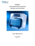
PRIZMA
Automated Swimming Pool
Monitor and Controller
User Manual US
Version 2.18
1
Table of Contents
1.
2.
3.
General Safety Precautions............................................................................................................................................. 4
General Overview ........................................................................................................................................................... 5
Safety Information .......................................................................................................................................................... 6
3.1.
Intended Use ........................................................................................................................................................... 6
3.2.
Safety Precautions .................................................................................................................................................. 6
4.
Installation ...................................................................................................................................................................... 7
4.1.
Working Environment ............................................................................................................................................. 7
4.2.
Required Components ............................................................................................................................................ 7
4.3.
Basic Installation ..................................................................................................................................................... 8
4.4.
Plumbing Installation .............................................................................................................................................. 8
®
4.4.1.
PRIZMA Controller......................................................................................................................................... 8
4.5.
Cl and pH Connection to External Dosing Pumps ................................................................................................... 9
4.6.
Electrical Installation ............................................................................................................................................... 9
4.6.1.
Connecting Relays (external dosing systems) .............................................................................................. 10
4.6.2.
pH (+) and pH (-) setting ............................................................................................................................... 12
4.6.3.
Connecting External Communication ........................................................................................................... 12
4.6.4.
Connecting the Empty Tank Alarms ............................................................................................................. 13
4.6.5.
Connecting External Flow Switch ................................................................................................................. 13
4.7.
Completing the Installation .................................................................................................................................. 13
5.
Controller Settings and Software Set-up ...................................................................................................................... 14
®
5.1.
PRIZMA Setup (Via Panel interface) ..................................................................................................................... 14
5.2.
Connecting the TDU (Technical Device Unit) ........................................................................................................ 14
5.3.
General Manu Navigation ..................................................................................................................................... 15
5.4.
Main Menu 1: Chlorine Settings ........................................................................................................................... 16
5.5.
Main Menu 2: pH Settings .................................................................................................................................... 16
5.5.1.
Cl and pH Feed Rates ................................................................................................................................... 16
5.6.
Main Menu 3: Calibration and Pool Volume ........................................................................................................ 17
5.6.1.
Calibrating Cl and pH .................................................................................................................................... 17
5.6.2.
Setting Pool Volume ..................................................................................................................................... 18
5.7.
Main Menu 4: Pump Operation and Test Now ..................................................................................................... 18
5.7.1.
Testing Cl and pH Feed System .................................................................................................................... 18
5.7.2.
Test Now ...................................................................................................................................................... 18
5.8.
Menu 5: Additional Pool Information ................................................................................................................... 18
5.9.
Menu 6: ................................................................................................................................................................. 20
5.10.
Technical Menu ................................................................................................................................................ 20
5.11.
Technical Menu 1 and Technical Menu 2 ......................................................................................................... 20
5.12.
Tech Menu 3: TDU Settings .............................................................................................................................. 21
5.13.
Tech Menu 4: Remote Settings Continued and Testing ................................................................................... 21
5.14.
Tech Menu 5: Display Mode Selection ............................................................................................................. 21
6.
Controller Settings and Software Set-up Using iPRIZMA® Smartphone App ................................................................ 22
6.1.
WiFi set-up ............................................................................................................................................................ 23
6.2.
Downloading the iPRIZMA® smartphone app ...................................................................................................... 23
6.3.
First time connection to PRIZMA® using iPRIZMA® ............................................................................................. 23
6.4.
Using iPRIZMA® user manual ................................................................................................................................ 23
7.
Normal Operation ......................................................................................................................................................... 23
8.
Emergency Mode .......................................................................................................................................................... 24
9.
Test Counter ................................................................................................................................................................. 24
10.
SPA Mode .................................................................................................................................................................. 25
11.
Alarms and Troubleshooting ..................................................................................................................................... 26
12.
Maintenance ............................................................................................................................................................. 26
12.1.
Replacing the Test-strip Cassette ..................................................................................................................... 26
12.2.
Filter Maintenance ........................................................................................................................................... 27
2
12.3.
Prizma® Maintenance Kit ................................................................................................................................. 27
12.3.1.
Parts Included .......................................................................................................................................... 28
12.3.2.
Removing the Prizma® Cover ................................................................................................................... 28
12.3.3.
Replacing Flow Switch ............................................................................................................................. 29
12.3.4.
Replacing Pump Housing ......................................................................................................................... 30
12.3.5.
Replacing the Prizma® Cover ................................................................................................................... 33
Appendix A - PRIZMA® Specifications .................................................................................................................................... 34
Appendix B – PRIZMA® Blow-Apart Diagram ......................................................................................................................... 35
3
1.General Safety Precautions
This section presents important information intended to ensure safe and effective use of this
product.
Read the following carefully before handling the product. These warnings and cautions must be
followed carefully to avoid injury to yourself or damage to equipment.
Warning: Only properly trained and licensed
electricians should attempt to wire or service the
®
electronic components of the PRIZMA Controller.
Attention! Seuls des électriciens qualifiés ayant reçu la
formation adéquate peuvent entreprendre le branchement,
l’entretien ou la réparation des composants électroniques du
®
contrôleur PRIZMA .
There is an Electrical Shock Hazard when servicing this
system.
Il existe un risque de choc électrique lors de l’entretien de ce
système.
Always verify that all electrical power source(s) are off
before opening the analyzer/controller unit or
attempting to service electronic components or
wiring.
Ayez soin de toujours vérifier que la ou les source(s)
d’alimentation électrique est ou sont bien déconnectée(s)
avant d’ouvrir l’unité ou d’entreprendre toute opération de
service technique et tout branchement des composants
électroniques.
Caution: Extreme caution should be used when
®
installing, operating, and maintaining the PRIZMA
Controller. Only properly trained technicians are
authorized to install and maintain the controller.
Attention! Il y a lieu d’agir avec une extrême prudence lors de
l’installation, de la mise en œuvre et de la maintenance du
®
contrôleur PRIZMA . Seuls des techniciens dûment formés à
cet effet sont autorisés à effectuer l’installation et la
maintenance du contrôleur.
Only properly trained and licensed swimming pool
operators should attempt to make any changes to
chemical dosing levels.
Seuls des opérateurs qualifiés de piscine dûment formés à cet
effet sont habilités à modifier les dosages des produits
chimiques utilisés.
Always follow local health and safety regulations
when performing any service on the
analyzer/controller unit or when changing chemical
dosing settings.
Conformez-vous sans exception aux consignes locales de santé
et de sécurité lorsque vous effectuez toute opération
technique sur l’analyseur/le contrôleur, ou lorsque vous
modifiez les paramètres de dosages chimiques.
®
®
Caution: The PRIZMA is shipped as 110-120V AC.
Confirm the required voltage before making any
electrical connections.
Attention! Lors de sa livraison, le PRIZMA est paramétré pour
un branchement électrique à 110-120V AC. Assurez-vous de la
tension électrique applicable avant d’effectuer un quelconque
branchement électrique.
Each relay connection is limited to 4 amps, to prevent
overheating. The relays may show a higher rating but
do not connect equipment exceeding 4 amps.
Chaque connexion relais est limitée à 4 Amp. afin d’éviter
toute surchauffe. Même si les relais affichent éventuellement
une valeur supérieure, ils ne se connecteront pas à un élément
dépassant 4 Amp.
All electrical connections should comply with National
Electrical Code (NEC) and all local regulations.
Tous les branchements électriques doivent être conformes au
Code Electrique National (NEC – National Electrical Code) ainsi
qu’à toutes les consignes locales.
Caution: PRIZMA's control board unit should not be
opened except for initial installation and
troubleshooting, and should only be opened by a
trained and approved technician.
Attention! Le tableau de commandes du contrôleur PRIZMA
ne doit en aucun cas être ouvert si ce n’est lors de l’installation
initiale et en cas de dépannage – auquel cas son ouverture ne
doit être effectuée que par un technicien ayant reçu la
formation adéquate et dûment habilité.
®
4
2.General Overview
The PRIZMA® automatic swimming pool controller performs tests for chlorine and pH. The test results are
displayed in a scale of low, normal or high on the front panel. The PRIZMA® automatically controls chlorine
and pH dosing in order to optimize the pool’s chemicals and to maintain personal and environmental safety.
Info/Alarms (1) Test Frequency (2)
pH and Cl Levels (3)
Test Now (4)
Figure.1 User Interface Panel
5
Cl Tank Empty (5)
3.
Safety Information
3.1. Intended Use
®
This manual is for qualified and trained pool service technicians who will install and service the PRIZMA
Controller. It provides instructions on how to install the controller, how to integrate it with external pool chemical
dosing systems, as well as how to calibrate, operate, and maintain the system. Included in this document is
some general information on how pool water quality is monitored and maintained, but it does not teach how to
operate swimming pools or administer chemicals.
3.2. Safety Precautions
Warning: Only properly trained and licensed electricians should attempt to wire or service the
electronic components of the controller. There is an Electrical Shock Hazard when servicing this
system. Always verify that all electrical power source(s) are off before opening the controller
unit or attempting to service electronic components or wiring.
Caution: Extreme caution should be used when installing, operating, and maintaining the PRIZMA®
Controller. Only properly trained technicians are authorized to install and maintain the controller.
Only properly trained and licensed electricians should attempt any change to the system’s
electrical components. Only properly trained and licensed swimming pool operators should
attempt to make any changes to chemical dosing levels.
Always follow local health and safety regulations when performing any service on the controller or changing
chemical dosing settings.
Note: The protection provided by the equipment may be impaired if the product is used in a manner not
specified in this manual.
Note: Blue I Water Technologies Ltd. does not accept any responsibility for any damage caused to its
products by unauthorized personnel.
USE OF NON-BLUE I WATER TECHNOLOGIES’ REPLACEMENT PARTS WILL VOID ALL WARRANTIES.
Note: PRIZMA® mains power plug is a disconnected device. Mains power connection should be accessed
easily:
Connect to an appropriate power inlet with comfortable access
Connect to a connection box with appropriate circuit breaker
Only a safety-certified plug shall be connected to the cord during the unit installation according to
national standard
Note: Mains power fuse rating:
Replace a fuse with the same type and rating.
Supplied Voltage
120VAC
230VAC
Fuse Type
0.25 slow blow
0.15 slow blow
Manufacture Name
“Littelfuse”
“Littelfuse”
Manufacture P/N
218.250XP
218.125XP
Note: PRIZMA® meets installation category II – Overvoltage categories
Note: Damaged power cord should not be used and must be replaced by manufacture or its service agent in
order to avoid hazard
Note: PRIZMA® is intended for pollution degree 2
6
4.Installation
For an easier view of the PRIZMA® display, it is recommended to install under a sunshade.
WARNING
The chlorine and pH dosing systems should be installed AFTER the pool equipment (heater etc.)
WARNING
Chlorine injection into water pipe must be 50cm (20Inch) apart from acid or base injection into water pipe.
Figure.2 Installation Schematics
4.1. Working Environment
Pollution Degree: 2
Installation Category: 2
Altitude: 2,000 m
Humidity: 1 to 90% non-condensing
Electrical Supply: 100-115Vac, 1.0A or 200-230Vac, 0.5A, 50/60Hz
Temperature: 5°C to 45°C*
4.2. Required Components
Supplied with the Controller:
PRIZMA® wall mount adapter
Test strip cassette
Tubing to and from PRIZMA®, 10m (33 feet) of 6mm (1/4”) O.D with 4 plumbing fittings
Power cord, 1.8m (5.9 feet) cord provided with plug
pH and Cl dosing pumps power cords with socket , 15 cm (5.9”)
Dosing pump socket enclosure safety lock
If software setup is not being performed with the iPrizma app and Wi-Fi connection, a TDU (Technical Device
Unit) is required to perform software set-up changes and is usually kept by the technician.
NOTE
A single TDU can be used to program multiple PRIZMA® controllers.
*For optimal measurement accuracy, water temperature should be between 15°C and 38°C (59°F–100.4°F).
7
Every pool is slightly different so be aware of the pool’s plumbing configuration and sizes before installing.
The installer will need to supply all additional components to complete the installation. Make sure that you
have all required parts on-site, including:
Installation materials for attaching PRIZMA® to the wall or to other mounting surface
Plumbing Fittings and Tubing required to supply water to and from the controller (6mm (1/4”) O.D)
Plumbing Fittings and Tubing required to inject chemicals to the water (6mm (1/4”) O.D)
Electrical cord to supply power to the controller
Electrical cords to connect controller to dosing systems
4.3. Basic Installation
1.
Mount the PRIZMA®'s wall mount adapter on a stable wall or surface, preferable at eye level
2.
Connect the PRIZMA® to the wall mount adapter, making sure the adapter rails are securely inserted
in the PRIZMA®
Figure.3 Well Mount Installation
4.4. Plumbing Installation
4.4.1.
PRIZMA® Controller
NOTE
PRIZMA® should be installed after a water filter of at least 130micron
1.
Connect the water inlet tube to the pool’s circulation system after the filter and before the chemical
dosing systems.
NOTE
If the pressure is greater than 15 psi (1 bar) a pressure reducer will be required.
8
2.
Connect the water outlet tube to the pool’s circulation system on the suction side of the pump.
NOTE
A 4 psi (0.25 bar) pressure difference is required between the PRIZMA®’s inlet and outlet.
3.
Optional: connect a drain line to the sampling drain port
4.5. Cl and pH Connection to External Dosing Pumps
This section applies to Cl and pH connection to dosing pumps. For the dosing pumps infromation, refer to
the manufacturers’ instructionsfor proper installation.
pH pump
connection
Socket
enclosure
Cl pump
connection
Figure.4 Dosing Pumps Cables & Socket Enclosure
1. Connect the Cl connector to Cl Dosing Pump and protect the connection using the extension cord safety
lock.
2. Connect the pH connector to pH Dosing Pump and protect the connection using the extension cord safety
lock.
NOTE
The dosing pump socket enclosure safety lock MUST be installed in a vertical position as shown in the picture, to ensure
the connection is protected from ingress.
4.6. Electrical Installation
CAUTION
The PRIZMA® is shipped as 110-120V AC. Confirm the required voltage before making any electrical
connections.
CAUTION
Before opening the cover, make sure ALL electrical sources to the PRIZMA® are OFF.
NOTE
The maximum voltage for PH Ext. and CL Ext. inputs shall not exceed 250VAC and 4A MAX. Wiring connection
shall be 17AWG MIN, Rated voltage: 100-250VAC, Minimum rated current: 10A, Flammability rating: F1
9
NOTE
EXT. FLOW SW, PH Tank Empty, CL Tank Empty inputs shall be limited to 16V r.m.s and 22.6V peak and
35VDC
The PRIZMA® must remain connected to its power supply continuously (24/7) to ensure proper operation of
timed water tests.
4.6.1.
Connecting Relays (external dosing systems)
No additional wiring is required for the PRIZMA® Integrated Cl and/or pH pumps. This section is for external
chlorine and/or pH dosing systems.
The relays controlling the dosing systems are dry contacts and do not have power. They operate as a switch
for the power and only the line (live) wire of the power supply should be connected to the Cl ext. or pH ext.
terminal blocks.
Power
Supply
pH Tank
Empty
Switch
Rs
485
Cl Tank
Empty
Switch
External
pH Ext.
Flow
(Relay)
Switch
Cl Ext.
(Relay)
Figure.7 Main Card
1. Connect the earth wire to the ground return wire from each of the controlled dosing systems.
2. Connect the neutral wire to the return wire from each of the controlled dosing systems.
3. Connect the line (live) wire to the connector marked Com of each relay.
4. Connect the line wire from the dosing system to the connector marked N.O. or N.C. as appropriate of each
relay.
a. N.O. = Normally Open means that the Cl or pH feeder will only receive power when the PRIZMA® calls for
Cl or pH feed.
b. N.C. = Normally Closed means that the Cl or pH feeder will always receive power except when the
PRIZMA® calls for Cl or pH feed.
10
Example Relay Wiring
This section is for general information only and is not intended to fit every possible dosing system. If you are
unsure of the proper wiring configuration, consult the dosing system manufacture for specific electrical
requirements.
1. Dosing Pump or Solenoid Valve
i. Dosing will turn ON based on PRIZMA® decision to add chemicals
ii. Connect the Line (live) wire through COM and N.O.
Cl or pH Pump
2. Salt Chlorinator
a. Dosing will turn ON based on PRIZMA® decision to add chemicals
b. Connect the Line (live) wire through COM and N.O.
3. Salt Chlorinator (dry contact or 24V)
11
a.
b.
c.
d.
Dosing will turn ON based on PRIZMA® decision to add chemicals
Connect 24V wire between COM and N.C.
The Chlorinator will receive 24V all the time. ("OFF" dousing time)
The voltage will disconnect from salt generation ("ON" dosing time) based on PRIZMA® decision to
add chemicals
CAUTION
Each relay connection is limited to 4 Amps, to prevent overheating
Make sure that voltage to the dosing system is correct before connecting power supply
PRIZMA®'s cover should not be opened except for initial installation and troubleshooting
4.6.2.
pH (+) and pH (-) setting
PRIZMA® default setting coming with pH (-) control (Acid). The controller is adding acid to balance the pool
until reaching the set point.
pH (+) control can be set by switching the position of the lock (see photo below) on the bottom part of the
PRIZMA®. In that case, the controller will add base until reaching the set point. The keys are supplied with
the controller.
Figure.8 Acid or Base Key & Switch
4.6.3.
Connecting External Communication
The RS-485 connection is used for external communication including the optional WaterGuardOL Wireless
Communicator (Modem). See WaterGuardOL manual for communicator details.
12
1.
Connect the ‘+’ on the PRIZMA® RS485 terminal block to the ‘+’ of the communicator RS485 terminal
block
2.
Connect the ‘-’ on the PRIZMA® RS485 terminal block to the ‘-’ of the communicator RS485 terminal
block
4.6.4.
Connecting the Empty Tank Alarms
These connections allow for sensors in the chlorine and pH feed systems to display alarms when the chlorine
and pH run out. The sensors are not supplied with the controller.
Sensor must supply dry contact (ON/OFF) signal to be recognized by PRIZMA®.
Follow tank sensor manufacture directions for installation and confirmation of wiring
Connect the two wires from the tank sensor to the Ground and IN of the Cl or pH empty terminal block.
4.6.5.
Connecting External Flow Switch
The external flow switch provides another layer of safety against accidental chemical dosing in the case of no
flow in the pool’s circulation system where chemicals are being added (i.e. during backwash). PRIZMA®
supports both 2 and 3 wire flow switches.
Follow flow switch manufacturer directions for installation and confirmation of wiring.
Place a jumper (short) connection J21 Flow Control, located on top right of main electronics card.
When a 2 wire switch is used, it should be connected to the “INP” and “GND” connections on
PRIZMA®.
When a 3 wire switch is used, the “VCC” connection will also be used. After connection check for
proper operation and change wire order if not working.
4.7.
Completing the Installation
1.
If the PRIZMA® was opened for inner connections return the cover making sure that all screw are
securely in place; do not over tighten (Figure 5)
2.
Install a new cassette, close the door and lower tabs to hold door in place (Figure 8)
Figure.9 Replacing the test strip cassette
3. Connect the supplied power cord to the appropriate electrical power socket.
13
CAUTION
Connect to the power after completion of all installation activities
15 min after powering the PRIZMA® cassette will load automatically, start to test and control the pool.
Power Cord
Figure.10 Power Cord
5.
Controller Settings and Software Set-up
To ensure that PRIZMA® is able to control most effectively, it must be configured to the specific pool to
account for differences in: pool volume, chemical feed rates, and set-points.
5.1.
PRIZMA® Setup (Via Panel interface)
PRIZMA® comes with a default setup or special setup per the customer need. Via the panel interface one can
setup the measurement interval mode. One can toggle between the 3 tests mode options by pressing the
Test Mode (Figure 1) button.
1 – One test per day (a test every 24 hours)
2 – Two tests per day (a test every 12 hours)
3 – Three tests per day (a test every 8 hours)
5.2.
Connecting the TDU (Technical Device Unit)
If PRIZMA® is not being set up and controlled using the iPrizma app and Wi-Fi
connection, a TDU (Technical Device Unit) is required and is usually kept by the
technician. To ensure that PRIZMA® is able to control most effectively, it must be
configured to specific pool group to account for differences in: pool volume,
chemical feed rates, and set-points. This can be preordered as factory setup or
accomplished through the TDU (Technical Device Unit), which is also used to
calibrate the controller. Connect the TDU to the 15-pin connector on the bottom
of the PRIZMA® and the controller will automatically enter programming mode.
Remove the connector cap before connecting the TDU.
Figure.11 TDU (Technical Device Unit)
14
NOTE
Do not forget to place the connector cap back in place, after disconnecting the TDU, in order to protect the
connector from corrosion.
1. Connect the cable from the TDU to the 15-pin connector on the bottom of the PRIZMA®
TDU Connection: 15-pin Connector
Water
Outlet
Water
Inlet
Drain port
Figure.12 TDU Connection Port
2. Press and hold PWR for 3 seconds until the back-light on the TDU turns ON
3. The software and hardware version of the TDU will appear on the screen
NOTE
In case the TDU SW version is different from the one mentioned in this manual, some menus will be missing
from the TDU.
a.
Connection Status
1.
If a PRIZMA® controller is properly connected, the screen will display the PRIZMA® ID and any
active alarms
If a PRIZMA® controller is not properly connected, the TDU will show “Device Not Found” and
will shut down
Battery Life -- on the top right corner of the display
2.
b.
5.3.
General Manu Navigation
MEN. Enters the menu
PWR. Turns TDU ON/OFF
ESC. Exits Menu and send changes to PRIZMA®
OK Makes a Selection or Accept Change
15
UP/DOWN Arrows Changes Menu or Setting Value
LEFT/RIGHT Arrows Changes Setting Value
5.4.
Main Menu 1: Chlorine Settings
1. Press MENU
2. Use the UP or DOWN Arrows to select “CL Set-Point” and Press OK
3. Use the UP or DOWN Arrows to enter the “CL Set-Point” and Press OK
4. Use the LEFT or RIGHT Arrows to select YES and Press OK to Save Changes
5. Use the UP or DOWN Arrows to select “Cl Feed Rate” and Press OK
6. Use the UP or DOWN Arrows to enter the “Cl Feed Rate” and Press OK
7. Use the LEFT or RIGHT Arrows to select YES and Press OK to Save Changes
NOTE
The default value depends on the display mode selection. Refer to section 4.12 “Tech Menu 5: Display Mode
Selection” for the default values
5.5.
Main Menu 2: pH Settings
1. Press MENU (if already in menu do not need to press again)
2. Use the UP or DOWN Arrows to select “pH Set-Point” and Press “OK”
3. Use the UP or DOWN Arrows to enter the “pH Set-Point” and Press “OK”
4. Use the LEFT or RIGHT Arrows to select “YES” and Press “OK” to Save Changes
5. Use the UP or DOWN Arrows to select “pH Feed Rate” and Press “OK”
6. Use the UP or DOWN Arrows to enter the “pH Feed Rate” and Press “OK”
7. Use the LEFT or RIGHT Arrows to select YES and Press “OK” to Save Changes
NOTE
The default value depends on the display mode selection. Refer to section 4.12 “Tech Menu 5: Display Mode
Selection” for the default values
5.5.1.
Cl and pH Feed Rates
The feed rate is the output of the feed system in (l/h or gal/day) and the controller assumes 12% sodium
hypochlorite solution for chlorine and Muriatic Acid / HCL for pH. If using diluted solutions or different feed
systems adjust accordingly.
Table 1 provides estimates for starting points. The table can be used as well for conversions for specific feed
rates of the dosing system provided by the manufacturer.
16
Table.1 Cl Feed Rate
NOTE
A Lower feed rate will increase the amount of time the feeder is ON. A higher feed rate will decrease the
amount of time the feeder is ON.
If the pool is consistently below the set-point, lower the feed rate.
If the pool is consistently above the set-point, raise the feed rate.
NOTE
Chlorine / pH dosing feed rate is 1.1-7 (l/h or gal/day)
5.6.
Main Menu 3: Calibration and Pool Volume
NOTE
The PRIZMA® is calibrated in factory and there is no need for site calibration.
Skip the calibration menus.
5.6.1.
Calibrating Cl and pH
NOTE
It takes approximately 2 weeks after installation for the pool’s chemical levels to stabilize.
When calibrating, make sure that water for the manual test is taken from the sample line to the
PRIZMA® Controller; not directly from the pool.
The Cl and pH must be in measurement range (Cl between 0.5 to 5.0ppm and pH between 6.5 to 8.2)
in order to calibrate. If the Cl or pH is out of measurement range an alarm of “Out of Range Balance the
Pool”. Calibration should be performed when the pool operates at or near +/- 25% of the set-points for both
Cl and pH.
1. Press “MENU”
2. Use the UP or DOWN Arrows to select “Cl CALIBRATION” and Press “OK”
3. Display will show “CL Value” and “Sensor Value”. The “Cl Value” is the calibrated value for Cl and the
“Sensor Value” is the measured Cl level with no calibration.
4. Press “OK”
5. Display will show Wait for Measurement
a. Measurement cycle will start
17
b. If there is a problem with the test preventing calibration (i.e. no flow or no cassette), the TDU will
display “Check Alarms”.
Perform external calibration test on the water from the PRIZMA® sample line using a digital
photometer.
7. Wait for measurement to complete (TEST NOW Light will go out when complete)
8. Use the UP or DOWN Arrows to change the “CALIBRATE TO” value to match the manual test and Press
“OK”
9. Use the LEFT or RIGHT Arrows to select “YES” and Press “OK” to Save Changes
10. Repeat Steps 2-9 for pH Calibration
6.
5.6.2.
1.
2.
3.
4.
Press “MENU” (if already in menu do not need to press again)
Use the UP or DOWN Arrows to select “POOL VOLUME” and Press “OK”
Use the UP or DOWN Arrows to enter the “POOL VOLUME” and Press “OK”
Use the LEFT or RIGHT Arrows to select “YES” and Press “OK” to Save Changes
5.7.
Main Menu 4: Pump Operation and Test Now
5.7.1.
1.
2.
3.
4.
5.
6.
7.
8.
Setting Pool Volume
Testing Cl and pH Feed System
Press “MENU” (if already in menu do not need to press again)
Use the UP or DOWN Arrows to select “Cl Pump opr” and Press “OK”
Use the LEFT Arrow to select “ON”
Confirm that the Cl pump or dosing system turns ON
Use the RIGHT Arrow to Select “OFF”
Confirm that the Cl pump or dosing system turns OFF
Press “OK”
Repeat Steps 2-8 for “pH Pump opr”
5.7.2.
Test Now
1.
Press “MENU” (if already in menu do not need to press again)
2.
Use the UP or DOWN Arrows to select “Test Now” and Press OK
3.
Use the LEFT or RIGHT Arrows to select YES and Press OK
4.
Measurement cycle will start
5.
If there is a problem with the test (i.e. no flow or no cassette), the TDU will display “Check Alarms”.
5.8.
Menu 5: Additional Pool Information
In order to accurately account for the evaporation rate of the chlorine, additional information about the
specific pool is required.
1. Press “MENU” (if already in menu do not need to press again)
18
2. Use the UP or DOWN Arrows to select “Stabilized” and Press “OK”
a. The stabilized option refers to the use of stabilized chlorine such as di-chlor and tri-chlor and/or using
cyanuric acid.
b. Use the LEFT Arrow to select “Yes” or “No” and Press “OK”
3. Use the UP or DOWN Arrows to select “Pool Cover” and Press “OK”
a. Use the LEFT Arrow to select “Yes” or “No” and Press “OK”
4. Use the UP or DOWN Arrows to select “Indoor” and Press “OK”
a. Use the LEFT Arrow to select “Yes” or “No” and Press “OK”
5. Press “ESC”
6. A message asking if you want to send all changes will appear on the display. Use the LEFT Arrow to Select
Yes to Send the Changes to the PRIZMA®.
7. The TDU will return to the main menu display.
19
5.9. Menu 6:
8. Use the UP or DOWN Arrows to view Test Counter
9. Use the UP or DOWN Arrows select Spa Volume and Press “OK”.
10.Use the UP or DOWN Arrows to select the SPA volume and Press “OK”
11.Use the LEFT Arrow to select “Yes” or “No” and Press “OK”
12.Use the UP or DOWN Arrows select Spa Meas. Int. and Press “OK”
13.Use the UP or DOWN Arrows to select the Spa Meas. Int. and Press “OK”
14.Use the LEFT Arrow to select “Yes” or “No” and Press “OK”
5.10.
Technical Menu
This Menu shows additional information about the PRIZMA® that may be useful in troubleshooting problems
as well as the TDU set-up.
To enter the Technical Menu:
1. Press “MENU”
2. Press UP and DOWN Arrows TOGETHER
5.11.
Technical Menu 1 and Technical Menu 2
These menus show additional information about the connected PRIZMA®. NO changes can be made to these
values; it is for information only. Descriptions of each are below:
Temperature: Temperature inside the PRIZMA® Controller in °C
Evap Factor: Evaporation Factor PRIZMA® is using (based on settings in Menu 5)
Light Intens: Light Intensity of the LEDs
SW ver num: Software Version of the connected PRIZMA®
HW ver num: Hardware Version of the connected PRIZMA®
Protocol #: Communication Protocol of the connected PRIZMA®
20
5.12.
Tech Menu 3: TDU Settings
This menu allows for selecting US or Metric units and Language of the TDU
1. Use the UP or DOWN Arrows to Select “Pool Vol” and Press “OK”
2. Use the LEFT or RIGHT Arrows to Select between “m3” or “gal” and Press “OK”
3. Use the UP or DOWN Arrows to Select “Feed Rate” and Press “OK”
4. Use the LEFT or RIGHT Arrows to Select between “L/hr” or “gal/day” and Press “OK”
5. Use the UP or DOWN Arrows to Select “Language” and Press “OK”
6. Use the LEFT or RIGHT Arrows to Select the Language of the TDU and Press “OK”
M
3
1
3
5
7
10
20
30
40
Pool Volume Configuration
3
Gallons
M
Gallons
(appox.)
(appox.)
260
50
13,200
790
60
15,800
1,320
70
18,500
1,840
90
23,700
2,640
110
29,000
5,250
130
32,300
7,900
150
39,600
10,500
170
45,000
Table.2 Pool Volume Configuration
5.13.
Tech Menu 4: Remote Settings Continued and Testing
This menu is destined for future features.
5.14.
Tech Menu 5: Display Mode Selection
This menu allows for selecting display mode and setting the unit address.
1. Use the UP or DOWN Arrows to Select “Display Conf.” and Press “OK”
2. Use the LEFT or RIGHT Arrows to Select between the modes “RGL Mode ” or “BNK Mode” or “MTR Mode”
or “OX-Hot Mode” or “OX-Cold Mode” and Press “OK” (Table 3)
3. Use the UP or DOWN Arrows to Select “Address” Press “OK” and then use the LEFT or RIGHT Arrows to set
PRIZMA® address” and Press “OK”
Use the UP or DOWN Arrows to Select “SPA Mode” and Press “OK” to activate the mode.
Press ESC. choose “to send the information to PRIZMA®. Cl Tank Empty LED will blink on/off at a rate of
500msec. (Figure 1, parameter 5). For deactivation of SPA Mode press “OK” and then ESC. the “Cl Tank
Empty” will stop blinking.
21
pH
Scale Values
RGL
BNK
MTR
OX Hot
Countries
OX Cold
Countries
High
> 8.0
>8.0
>8.1
>8.0
>7.7
7.8 – 8.0
7.5 – 8.0
7.8 – 8.1
7.8 - 8
7.5-7.7
7.0 – 7.6
7.0 – 7.4
7.0 – 7.6
7 - 7.6
7-7.4
6.5 – 6.9
6.5 – 6.9
6.5 – 6.9
6.5 - 6.9
6.5-6.9
< 6.5
<6.5
<6.5
< 6.5
<6.5
Cl Scale
Values
RGL
BNK
MTR
Hot
Countries
Cold
Countries
High
> 5.1
> 1.5
0.9 - 1.0
> 2.6
>1.5
3.1 – 5.0
1.1 – 1.5
0.7 – 0.8
2.1 - 2.6
1.0-1.5
1.2 – 3.0
0.8 – 1.0
0.5 – 0.6
0.6 - 2.0
0.5-0.9
0.6 – 1.1
0.5 – 0.7
0.3 – 0.4
0.4 - 0.5
0.3-0.4
< 0.6
< 0.5
< 0.3
< 0.4
<0.3
Set Points
RGL
BNK
MTR
Hot
Countries
Cold
Countries
pH Set Point
7.0 –
7.6
Default 7.2
7.0 – 7.8
Default 7.2
7.0 – 7.6
Default 7.4
7.0 – 7.6
Default 7.2
7.0 – 7.4
Default - 7.2
Cl set Point
0.5 –
4ppm
Default –
1.5
0.5 –
4ppm
Default –
0.9
0.5 –
4ppm
Default –
0.8
0.8 –
1.3ppm
Default –
1.3
Normal
Low
Empty
Normal
Low
Empty
0.5 –
1.0ppm
Default – 0.9
Table.3 Display Mode Setting
6. Controller Settings and Software Set-up Using iPRIZMA® Smartphone
App
The PRIZMA® can be set up and controlled using a smartphone app instead of the TDU.
This can be used only with devices carrying the WiFi label:
22
6.1. WiFi set-up
Connect PRIZMA® WiFi antenna and open cable to enable better communication.
Antenna
Connection
6.2. Downloading the iPRIZMA® smartphone app
1. For iPhone users: Go to the App Store and download iPRIZMA® app.
2. For Android users: Go to the Google Play Store and download iPRIZMA® app.
6.3. First time connection to PRIZMA® using iPRIZMA®
Turn on WiFi in smartphone settings
6.4. Using iPRIZMA® user manual
To continue operating using iPRIZMA® refer to iPRIZMA® Application User Manual.
7.
Normal Operation
Under normal operation, the display will show pH and
Cl values in a scale of low, normal, and high based on
the chosen scale “display Mode”, for example RGL
mode has the following scale:
Only 1 LED will be illuminated and will indicate the
range of pH or Cl values.
In the example to the left, the pH is between 7.0 and
7.6 and the Cl is between 0.6 to 1.1 ppm.
The TDU will show the numeric values for the pH and
Cl test to the nearest tenth.
Figure.13 Normal Operation Indication Display
23
8.
Emergency Mode
NOTE
This mode is intended for pools operated with a salt chlorinator and with a rate feed of 0.1ppm.
NOTE
This mode is intended to be operated only when instructed by the pool technician.
NOTE
The emergency mode will keep dosing the pool with low level of chlorine without measurement until the
pool technician arrival.
The emergency mode intended use is for cases such as: pool water are not clear, PRIZMA® stopped working
(cassette ended) or inline filter is kluged.
Starting the emergency mode operation: press continuously for 4 sec on the test new button (figure 1). This
mode will dose the pool with a low feed rate via the salt chlorinator. As long as the PRIZMA® is set to work at
this mode the "Test Now" LED will blink on/off at a rate of 500msec. (Figure 1, parameter 4)
The pool technician can see this operation mode via the TDU as emergency mode alarm.
To return to normal operation: press continuously for 4 sec on the test new button. PRIZMA® will return to
pool normal operation mode and “Test Now” LED will stop blinking.
9.
Test Counter
Each measurement performed by the PRIZMA® is stored. The counter rests when a new cassette is
inserted.
The normal operation mode warning that a cassette is ending will warn when 25 measurement test
pads remains.
The test counter parameter can be viewed via the TDU as "Test counter".
Power LED will blink when cassette ends.
NOTE
Do not remove a cassette before ending. As the cassette has no identification, the insertion of a cassette will
trigger the counter rest.
24
10. SPA Mode
NOTE
This mode intended use is for SPA and swimming pool using the same water system (figure 12).
Figure.14 Pool and SPA shared water system.
To enable the SPA mode, connect the flow switch (figure 12) to the “Cl tank empty” in the PRIZMA®. Via the
TDU choose “SPA mode on” and use the table (table 4) to set up the pool and SPA parameters.
Pool volume
SPA pool volume
Pool operation mode
SPA measurement interval
Default setup
40 m3
2m3
2 measurements per day
Every 30min
Select from available range
1-170m3
1-10m3
1,2 or 3 measurements per day
Every 10-60 min
Table.4 SPA mode parameters
The 3-way valves A and B are contacted to an operator toggle button, switching from monitoring the
swimming pool (water loop 1) to monitoring the SPA (water loop 2). This operation is initiated by the pool
user whenever they wish to use the SPA.
As long as the PRIZMA® is set to work at this mode the "Cl Tank Empty" LED will blink on/off at a rate of
500msec. (Figure 1, parameter 4)
The pool technician can see this operation mode via the TDU as emergency mode alarm.
On return to pool normal operation mode and “Cl Tank Empty” LED will stop blinking.
25
11. Alarms and Troubleshooting
No Flow – flow to PRIZMA® is off or too low
1.
Check that water is flowing to and from PRIZMA® and correct problem preventing flow to controller
2.
Check that internal flow switch is rotating
Remove obstruction preventing flow switch from moving
Check wire connection on electronics card
Replace flow switch if necessary
Cassette End – Testing cassette is empty
Replace Cassette
Door/Cassette – cassette is not properly installed or door open.
Open door, remove cassette then insert cassette back and close door making sure to re-latch both latches for
the door.
Chlorine or pH too low/high
Use remote programmer to:
a.
Adjust set-point if not properly set
b.
Increase total amount of Cl or pH feed by:
Increasing Pool Volume or
Decreasing Feed Rate (yes decreasing)
c.
Decrease total amount of Cl or pH feed by:
Decreasing Pool Volume or
Increasing Feed Rate (yes increasing)
12. Maintenance
12.1.
Replacing the Test-strip Cassette
When the test-strip cassette is empty, the “cassette end” alarm will light-up.
1.
Elevate the tabs and open cassette door. (Figure 8)
2.
Remove the old cassette and discard.
3.
Open a new cassette and press into place.
4.
Close the door and lower the tabs to hold the door in place.
5.
The cassette will automatically load and testing and control will resume automatically
NOTE
The cassette is enveloped in a sealed cover for moisture control. The cassette sealed envelope should be
opened prior to installation. An open cassette expires within 4 months
26
12.2.
Filter Maintenance
It is recommended to rinse the filter at the beginning of the season as well each time after the pool
filter was treated.
1. Open the filter housing (figure 13 A) counter clockwise
while supporting the upper part.
2. Remove the filter (figure 13 B) and rains it well under
running water.
3. Insert back the filter and close the housing gently.
Figure.15 In-line housing and filter
CAUTION
Do not over tighten the filter housing.
12.3.
Prizma® Maintenance Kit
(Catalog number: 971-210-4003) Biennial maintenance kit for replacement of the sampling water
pump and the flow switch
This Prizma Maintenance Kit provides all the parts that should be replaced once every
two years (pump and flow switch) in order to maintain the Prizma®’s reliable and
continuous operation over time.
Maintenance kits can be purchased from your distributor or from the manufacturer.
Carefully follow the simple steps below to replace the pump and flow switch with the kit.
27
12.3.1.
Parts Included
A Flow switch
B Pump tube
C Rotor base and rotor cover
D Pump housing cover
E Grease
F Pump housing base
G Spare parts, including: Prizma door screws; pump pins; pump housing cover screws;
pump housing base screws
Warning:
Turn water off and disconnect power before beginning replacement of any Prizma® component.
12.3.2.
Removing the Prizma® Cover
The pump and flow switch are accessed by removing the Prizma® cover.
1.
2.
Gently remove the two screw
covers on the top corners of the
Prizma®, using a small flat-blade
screwdriver.
Remove the screws.
28
3.
Unlatch and open the cassette
door. Remove cassette.
4.
Loosen 5 screws as indicated.
(No need to remove
completely), and close the
cassette door.
5.
Release the Prizma® cover by
pulling carefully at the top
corners.
12.3.3.
Replacing Flow Switch
1. First remove the existing flow
switch. Locate and unplug the
existing flow switch connector
on the electronics card to
release flow switch wires.
(Marked “INT FLOW SW” on
electronics card).
2. Using plyers cut the cable ties
holding the flow switch in place
(on the plastic posts beneath
the pump housing base).
29
3. Remove the two tubes from the
flow switch heads.
4. Install the new flow switch [A]
by first securing the two tubes
to the flow switch heads.
5. Route the electric cord through
the opening to the electronics
card and attach the connector
(where marked “INT FLOW
SW”).
6. Secure the flow switch in place
using cable ties to attach one of
the black connectors to one of
the plastic posts beneath the
pump housing base, and the
electric cord to another post.
(See 2 above).
12.3.4.
Replacing Pump Housing
1. First remove the existing pump
housing. Remove the four screws
of the pump housing base.
30
2. Locate and unplug the existing
connector on the electronics card
to release flow switch wires.
(Marked “Water Pump motor” on
electronics card).
3. Route the wires out through the
opening from the electronics card.
Note: If necessary, loosen the
bottom screw of the MMI
electronics card and lift the card
slightly to make room for the
connector to be routed out.
4. Disconnect the two black tubes
from the two ends of the pump
tube.
5. Lift the pump (with pump motor
attached) and remove it to a work
surface.
Install the new pump housing:
6. Unscrew and dismantle the existing
pump housing cover.
7. With small plyers remove the rotor
cover and pump pins.
31
8. Gently lift and remove the pump
tube and then lift out the rotor
base.
9. Then unscrew the old pump
housing base from the motor, to
which the new pump housing will
be attached.
10. Screw the new pump housing [F]
onto the motor. (New screws are
supplied with the Maintenance
Kit.)
11. Proceed to construct the pump
using only new parts provided in
the Maintenance Kit.
12. Insert the rotor base [C] (knobs
side down) by fitting the flat side of
the center hole on the flat side of
the rotor axle.
13. Insert the four pump pins [G] and
secure in the depressions of the
rotor base. Then apply grease [E]
around the pins (cut a corner of the
grease sachet to apply).
14. Insert the pump tube [B], making
sure that the end with the ring is
on the bottom.
15. Apply some grease over the pipe,
between the pins.
32
16. Secure the rotor cover [C] over the
pins and then screw on the pump
housing cover [D].
17. Reconnect the Prizma’s two black
tubes to the ends of the pump
tube.
18. Route the new pump wires through
to the electronics card and plug the
new connector on the electronics
card where marked “Water Pump
motor”.
Note: If the bottom screw of the
MMI electronics card was loosened
to enable access, be sure to secure
it back in place.
19. Screw the pump into place.
12.3.5.
Replacing the Prizma® Cover
Follow in reverse steps 5-1 in Section 1 above (Removing the Prizma® Cover).
Reconnect the Prizma to its power supply to resume full operation.
33
Appendix A - PRIZMA® Specifications
GENERAL
Measurements
Operation mode
Measurements range
Colorimetric based, Free Chlorine & pH
Periodic & configurable
1, 2, and 3 times per day
pH: 6 - 9.1
Cl: 0.2 – 6.3ppm
Measurements accuracy
+/- 5%
Calibration
Flow rate
Automatic, after every measurement
60l/h (recycled into water source)
Test sample
10cc per test
Outside diameter of the fitting
6 mm
Pressure
Inlet 1 Bar max.
Number of tests
125 or 250 (Cl + pH)
COMMUNICATIONS
Digital
RS-485
Relays or cables
1xpH pump , 1xCl pump , salt chlorinator or tablet chlorinator
Sensors
pH/Cl Tank Empty, External flow available
Alarms
7
TDU (Technical Device Unit)
Via RS-485
Modem
Via RS-485
WiFi
iPRIZMA® smartphone application
ELECTRICAL
Input
110-120/210-240VAC; 60/50 Hz;
Power Consumption
15 VA max
MECHANICAL
Dimensions
470mm x 330mm x 130mm
18.5”x12.9”x5.1”
Weight
3.60kg w/out dosing pumps
4.5kg with dosing pumps
ENVIRONMENTAL
Operating Temperature
2°C to 55°C (35.6°F to 131°F)
Operating Humidity
1%-90% non-condensing
Enclosure type
IPx5
STANDARD COMPLIANCE
FCC
Safety
CE
FCC 47 CRF part 15 Subpart B Class B
CAN/CSA-C22.2 No. 61010-1
UL Std. No. 61010-1
AS/NZS 3136
EN 61326-1
EN 61010-1:01
34
Appendix B – PRIZMA® Blow-Apart Diagram
1
2
1
3
1
6
Part No
1
5
1
4
Description
#2 in the drawing
910-009-0000
Sampling Water pump
#3 in the drawing
910-000-4035
OMEGA T Holder
#4 in the drawing
910-000-4036
T 6 mm (tube Assembly)
#5 in the drawing
870-210-1109
Flow Meter (tube Assembly)
#6 in the drawing
910-000-4039
SERTO 6mm
#7 & 8 & 9 in the drawing
972-000-0090
6 mm Clear tube
#10 &11 in the drawing
970-210-0018
Niofren tube
#12 in the drawing
910-000-1000
Electronic MMI card
#13 in the drawing
910-000-2000
PRIZMA Main Electronic 1.5 AU(REV1:0)
#14 in the drawing
910-003-0000
Sub Assembly PRIZMA motor mount
#15 in the drawing
910-000-4025
Motor pin (black)
#16 in the drawing
910-000-4086
PRIZMA remote connector
®
®
®
35
No part of this publication may be reproduced, transmitted, transcribed, stored in a retrieval
system, or translated into any language or any computer language, in any form or by any third
party, without the prior written permission of Blue I Water Technologies Ltd.
Trademarks and Patents
PRIZMA is a registered trademark of Blue I Water Technologies Ltd.
Patents pending at the time of this printing
Disclaimer
Blue I Water Technologies Ltd. does not accept any responsibility for any damage caused to its
products by unauthorized personnel. Use of non-Blue I Water Technologies’ replacement parts
will void all warranties.
Blue I Water Technologies Ltd.
www.blueitechnologies.com
36