1
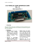
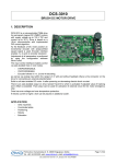
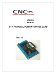
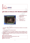
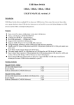
IO3 BREAKOUT BOARD DESCRIPTION Breakout board IO3 has digital buffer for STEP/DIR/ENA command signals and as such it is particularly suitable for the connection up to 4 microstep drives MST107 and/or to connect DC servo drives DCS-3010 directly to PC. This breakout board can also be used with all drives that have opto-isolated STEP/DIR/ENA inputs. On board charge pump prevents undesirable state changes in case of loss of communication with computer. Breakout board IO3 has two relay outputs that can be used to activate the two customers (electric motor for the main spindle and/or electric motor for vacuuming chips, etc.). Indication of the relay is performed using the two LEDs which are located on the board. One of the relay outputs can optionally be converted to analog output with a range of 0–5 V or 0–10 V which allows software to control of spindle motor revolution speed. Up to 5 limit switches can be connect to the breakout board. PC connection is performed via the parallel (printer, LPT) port. Breakout board has centronics (IEEE1284) connector, so that connection to the PC uses a standard printer cable. Breakout board IO3 is specially developed to be used with software for generating STEP/DIR command signals via parallel port such as: Mach2, Mach3, TurboCNC (free), KCam, etc. For power supply of the card uses the source 15–24 V DC / 500 mA. The breakout board has the voltage regulator for the proper operation. DESCRIPTION OF INPUT–OUTPUT PINS X axis STEP X axis DIR Y axis STEP Y axis DIR Z axis STEP Z axis DIR A axis STEP A axis DIR ENA (enable) Pin number on the side of PC (connector DB25) 2 3 4 5 6 7 8 9 17 Line type on the side of PC Output Output Output Output Output Output Output Output Output Safety signal (charge pump) 14 Output Spindle – Relay 1 1 Output Coolant – Relay 2 Limit switch 1 (SW1) Limit switch 2 (SW2) Limit switch 3 (SW3) Limit switch 4 (SW4) E-Stop – Limit switch 5 (SW5) 16 10 11 12 13 15 Output Input Input Input Input Input Description – function Prizma doo, Kumanovska str. 8, 34000 Kragujevac, Serbia Tel. +381 34 330 200, web: www.prizma.rs e-mail: [email protected] Doc: IO3_man_en Ver.1, January 2014. © by PRIZMA Annotation Can be optionally switched on and off Optionally analog output of 0–5 V or of 0–10 V Page 1 of 14 SPECIFICATIONS Number of axis 4 (X, Y, Z and A-axis) Axes control By STEP/DIR command lines separately for each axis, common ENA (enable) line for all axis Output current of STEP/DIR command lines 15 mA max Number of limit switches 5 Number of relay outputs 2 Analog output Choice 0–5 V DC or 0–10 V DC via jumper The capacity of one relay output 250 V AC / 8 A max Supply voltage 15–24 V DC / 500 mA Dimensions (W x L x H) 173 mm x 63 mm x 20 mm Weight ~120 g NOTE: specifications are subject to change without notice WIRING DIAGRAM OF BREAKOUT BOARD IO3 WITH MICROSTEP DRIVES MST-107 On the breakout board IO3 is possible to connect from 1 to 4 microstep drives MST-107. Connection of STEP/DIR/ENABLE command lines to microstep drives MST-107 is shown on Figure 1. For power supply of breakout board IO3 and to 4 microstep drives MST-107 it is recommended usage of power supply board with motor brake PSB-1 (Figure 2). More details about this power supply board and the way of installation can be found in the PSB-1 user manual. Users can also provide their own power source. In that case on Figure 3 is shown recommended power supply connection for breakout board IO3 and to 4 drives MST-107. Power supply must have two independent (isolated) power sources, one for power supply of breakout board IO3 (15-24VDC/500mA) and other for power supply of MST-107 drives with supply voltage 20-40VDC (electric current of this power supply depends on the used step motors – see manual for microstep drive MST-107). On +V supply wire, for each drive MST-107, is recommended usage of fast blow fuse to protect drives in case of overload. Prizma doo, Kumanovska str. 8, 34000 Kragujevac, Serbia Tel. +381 34 330 200, web: www.prizma.rs e-mail: [email protected] Doc: IO3_man_en Ver.1, January 2014. © by PRIZMA Page 2 of 14 Figure 1 Prizma doo, Kumanovska str. 8, 34000 Kragujevac, Serbia Tel. +381 34 330 200, web: www.prizma.rs e-mail: [email protected] Doc: IO3_man_en Ver.1, January 2014. © by PRIZMA Page 3 of 14 Figure 2 Prizma doo, Kumanovska str. 8, 34000 Kragujevac, Serbia Tel. +381 34 330 200, web: www.prizma.rs e-mail: [email protected] Doc: IO3_man_en Ver.1, January 2014. © by PRIZMA Page 4 of 14 Figure 3 Prizma doo, Kumanovska str. 8, 34000 Kragujevac, Serbia Tel. +381 34 330 200, web: www.prizma.rs e-mail: [email protected] Doc: IO3_man_en Ver.1, January 2014. © by PRIZMA Page 5 of 14 Installation of breakout board with PC, connection of end switches, connection of relays output and analog output is shown in Figure 4. NOTE: On the displayed scheme each axis has two limit switches, which are connected in parallel. When it is performed ”Home” positioning on that axis one of switches has Home switch function. In any other case, the activation of any of the two switches leads to stopping the machine. E-Stop switch is placed at the switch SW5. Figure 4 Maximum allowable current through each relay is 8A max, where total electric current should not be over 10A max. It is recommended that for electric current above 5A to be used external relays with larger capacity or contactors, and in that case contactors will be switched on by relays that are placed on breakout board IO3. NOTE: Negative output of Analog out is connected to the ground of breakout board IO3. Prizma doo, Kumanovska str. 8, 34000 Kragujevac, Serbia Tel. +381 34 330 200, web: www.prizma.rs e-mail: [email protected] Doc: IO3_man_en Ver.1, January 2014. © by PRIZMA Page 6 of 14 DIAGRAM OF BREAKOUT BOARD IO3 WITH DC SERVO DRIVES DCS-3010 Recommended installation diagram of breakout board IO3 with 3 DC servo drives DCS-3010 is shown in Figure 5. More details about this configuration can be found in user manual for DC servo drive DCS-3010. Figure 5 Prizma doo, Kumanovska str. 8, 34000 Kragujevac, Serbia Tel. +381 34 330 200, web: www.prizma.rs e-mail: [email protected] Doc: IO3_man_en Ver.1, January 2014. © by PRIZMA Page 7 of 14 Using breakout board IO3 with Mach 3 –setup– Demo version of the software Mach3 can be downloaded from the official site www.machsupport.com. As it is already mentioned breakout board IO3 is connected with PC by using parallel (LPT) port. For proper operation it is necessary to perform the required settings. All settings are in accordance with the schedule of input-output pins, which is shown in Table 1. Selection of the parallel port is performed in dialog box Config Ports and Pins (Figure 6). Figure 6 Setting of the STEP/DIR command lines for all axes is performed in dialog that opens by choosing option Config Ports and Pins Motor Outputs (Figure 7). In case of using microstep drive MST-107, considering that its step occurs on falling edge of STEP signal, it is necessary to select option Step Low Active (Figure 7). Figure 7 Setup for ENA (enable) command line is shown in Figure 15. Setup of step motor parameters depends of great number of factors: step motor type, applied drive (choice of microstep options), type of transmission (screw spindle, timing belt, etc.), mass of the moving parts of the machine etc. One potential setup is shown in Figure 8. Dialogue is opened by selecting Config Motor Tuning. Prizma doo, Kumanovska str. 8, 34000 Kragujevac, Serbia Tel. +381 34 330 200, web: www.prizma.rs e-mail: [email protected] Doc: IO3_man_en Ver.1, January 2014. © by PRIZMA Page 8 of 14 Figure 8 Proposal for setting the limit switches via option Config Ports and Pins Input Signals is shown in Figure 9 and 10. Setup refers to the connection of limit switches as shown in Figure 4. Figure 9 Figure 10 Prizma doo, Kumanovska str. 8, 34000 Kragujevac, Serbia Tel. +381 34 330 200, web: www.prizma.rs e-mail: [email protected] Doc: IO3_man_en Ver.1, January 2014. © by PRIZMA Page 9 of 14 Setup of relay outputs is performed in two steps. The first, by choosing the option Config Ports and Pins Output Signals (Figure 11) selects outputs that is used (in this particular case Output #2 i Output#3). Then it is needed to set the parameters under Config Ports and Pins Spindle Setup (Figure 12 area indicated by rectangle). Figure 11 Figure 12 Safety signal – Charge Pump When you start the computer and when you start the software Mach3 state of the output pins of the parallel port are not clearly defined. So, for example, a logic zero at the output pins 1 and 16 activates relay on the breakout board IO3, namely spindle motor, or some other output device, which in some cases may be a dangerous event. In order to avoid this situation use the safety signal (charge pump signal) that represents pulse trains that are generated after the successful start-up of management software (in case of using Mach3 software frequency of the charge pump signal is 12.5 kHz). To activate the use of the security signal it is necessary to set the jumper J1 to position Charge Pump ON (see Table 1). Prizma doo, Kumanovska str. 8, 34000 Kragujevac, Serbia Tel. +381 34 330 200, web: www.prizma.rs e-mail: [email protected] Doc: IO3_man_en Ver.1, January 2014. © by PRIZMA Page 10 of 14 TABLE 1 Jumper position J1 Charge Pump OFF – Circuit for charge pump signal is switched off. The output signals (Step, Dir, Enable and Analog out) are active no matter the charge pump signal is present or not. LED diode Charge Pump is switched on. Charge Pump ON – Circuit for charge pump signal is switched on. In the absence of the charge pump signal all logic outputs (Step, Dir and Enable) will be at logic zero state, while the Analog out voltage will be 0V. LED diode Charge Pump is switched off. When the charge pump signal is present, safety circuit will be activated and the output signals (Step, Dir, Enable and Analog out) will be active. LED diode Charge Pump is switched on. Setup the security signal (charge pump signal) is performed by selecting Config Ports and Pins Output Signals (Figure 13). Figure 13 Analog output Software Mach3 has the capability of generating Pulse-width modulation (PWM) signal. Pulse-width modulation is a method of control in which the frequency of the control signal does not change. Regulation is done by changing of the signal/pause ratio. To convert the PWM signal to a analog signal (voltage level), breakout board IO3 use active low pass filter. This filter smooth out the signal, filling in the gaps during the off periods of the PWM. The level of the analog signal depends on the signal/pause ratio. If the width of the signal is for example 10%, and width of the pause 90%, analog voltage will be 10% of maximum voltage. This analog signal can be used as a control spindle motor revolution speed. The use of analog output requires hardware setup of breakout board IO3 via jumpers which are in Table 2, and setting up of parameters in Mach3 software. TABLE 2 Jumpers position J2 and J3 if it is chosen analog signal. Jumper J2 should be switched to OFF. Jumper J3 defines the voltage level on the analog output. It can be in range of 0–5 V or 0–10 V. Prizma doo, Kumanovska str. 8, 34000 Kragujevac, Serbia Tel. +381 34 330 200, web: www.prizma.rs e-mail: [email protected] Doc: IO3_man_en Ver.1, January 2014. © by PRIZMA Page 11 of 14 Software setup is performed by selecting Config Ports and Pins Output Signals as it is showed in Figure 14, 15 and 16. NOTE: If it is used analog output, than it is not possible to use relay output named Spindle. For that reason it is necessary to put the jumper J2 in OFF position. Otherwise the PWM signal would go to the coil of the relay and buzzing from this relay will be heard. Figure 14 Figure 15 In Figure 16 it is seen that chosen fundamental frequency of PWM signal 250 Hz. It is important to notice the parameters relating to the Pulley Ratio#1 which is here set from 0-3000 RPM. This means that for signal/pause ratio of 0%, RPM will be 0, for 10% it will be 300 RPM and so on, while for 100% the spindle revolution speed will be 3000 RPM. Prizma doo, Kumanovska str. 8, 34000 Kragujevac, Serbia Tel. +381 34 330 200, web: www.prizma.rs e-mail: [email protected] Doc: IO3_man_en Ver.1, January 2014. © by PRIZMA Page 12 of 14 Figure 16 Commands related to the Spindle are on the main screen in the section called Spindle Speed (framed part in Figure 17). In the S field is required to enter the desired RPM (in Figure 15 it is 1000 RPM). Starting the spindle is achieved by pressing the Spindle CW F5 button or by pressing the F5 key on the computer keyboard. By pressing the + and – there is a continuous increase or reduction of RPM of the spindle for the size of specified increment. Figure 17 Prizma doo, Kumanovska str. 8, 34000 Kragujevac, Serbia Tel. +381 34 330 200, web: www.prizma.rs e-mail: [email protected] Doc: IO3_man_en Ver.1, January 2014. © by PRIZMA Page 13 of 14 DOCUMENT REVISION HISTORY January 2014. English version Prizma doo, Kumanovska str. 8, 34000 Kragujevac, Serbia Tel. +381 34 330 200, web: www.prizma.rs e-mail: [email protected] Doc: IO3_man_en Ver.1, January 2014. © by PRIZMA Page 14 of 14