1
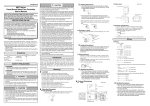
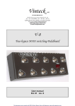
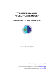
CP-UM-5376E WARNING RN748 Motor Driver (DC to Position Proportional Control Converter) User's Manual Thank you for purchasing the RN748. Before operating the product described in this user’s manual, please take note of the following points regarding safety. Be sure to keep this manual nearby for handy reference. Note that incorrect wiring of the RN748 can damage it and lead to other hazards. Check that the RN748 has been correctly wired before turning the power ON. Before wiring or removing/mounting the RN748, be sure to turn the power OFF. Failure to do so might cause electric shock or faulty operatoin. Do not touch electrically charged parts such as the power terminals. Doing so might cause electric shock. Do not disassemble the RN748. Doing so might cause electric shock or faulty operation. · A minimum of 15 meters away from a high voltage ignition device for a boiler. · No strong magnetic fields. · No flammable liquid or gas. • Devices or equipment connected to the RN748 must have basic insulation appropriate for the power supply voltage and the maximum operating voltage of the I/O units. • The RN748 requires a maximum of 5 seconds to start up after the power is turned ON. The RN748 can be used after it has started up. However, it is recommended to allow a warm-up time of at least 30 minutes so that it attains the specified accuracy. ■ Mounting Procedure · Mounting should be horizontal so that the top is not tilted up or down more than 10 degrees. · The mounting panel should be steel with a thickness of less than 9 mm. ● Connection of the RN748 ■ External Dimensions Terminals Power supply (unit: mm) 65 5 AC power supply 100 to 240Vac Mounting bracket (Accessory) 48 Terminal screw M3 CAUTION Control outputs 1 1 13 2 2 14 3 15 Event outputs 2005 Yamatake Corporation ALL RIGHTS RESERVED This manual explains the handling precautions, mounting, wiring, list of parameters and main specifications only. ■ Unpacking Check the following items when removing the RN748 from its package: Name Part No. Q'ty Mounting Bracket User's Manual 81409654-001 CP-UM-5376E 2 1 CAUTION 4 to 20mA dc signal This manual Input (IN) Center setting of rotation angle DI Digtal input 3 DI Digtal input 1 DI Digtal input 2 Warnings are indicated when mishandling this product might result in death or serious injury to the user. Cautions are indicated when mishandling this product might result in minor injury to the user, or only physical damage to this product. Proportional band setting Proportional band operation OUT Motor feedback input OPEN/CLOSE operation Selection of direct/reverse control action Event output1 DO Event output2 DO Event output3 DO 108 Stand-alone mounting 30min. Gang-mounting 44+0.5 0 Be sure to provide a switch within operator reach for shutting OFF the main power supply to the RN748 in the main supply wiring. Also, the main supply wiring requires a time-lagged (T) fuse (rated at 0.5A, 250 V). (IEC127) The following table shows the meaning of the symbols in the terminal wiring label on the side of the RN748: Symbols Open relay output Control output motor open operation Close relay output Control output motor closing operation Mounting ■ Location Install the RN748 in a location that fulfills the conditions listed below. · For common mode voltages of I/O except for power supply and relay contact output, the voltage to ground is 33Vr.m.s max., 46.7V peak max., and 70Vdc max. · Neither high nor low temperature / humidity. · Free from sulfide gas or corrosive gas. · Little dust or soot. · Locations protected from direct sunlight, wind or rain. · Little mechanical vibration and shock. · Not close to high voltage line, welding machine or electrical noise generating source. 1 G close Digital input DI 6 7 19 3 8 20 2 9 1 21 19 Selection of direct/reverse 20 Forced open/close 21 10 7 8 9 11 SG 24 24 Inputs Current 4 to 20mA 10 11 mA (unit: mm) (48xN–4) +0.5 0 Wiring Motor opening signal 5 ■ Panel Cutout Dimensions Handling Precautions • When three or more units are gang-mounted horizontally, the maximum allowable ambient temperature is 40°C. The RN748 calculates the MV (OUT) for the input (IN) according to the selection of direct/reverse control action, center setting of the rotation angle, and the setting of the proportional band; it also controls the ON/OFF status of the control output on the OPEN side and the CLOSE side so that the motor opening (MFB) calculated from the motor feedback input gets closer to the MV (OUT). The figure below shows the functional blocks of the RN748. Remarks SAFETY PRECAUTIONS WARNING Outline of functions T 92 +0.5 0 Ensure that this user's manual is supplied to the user before the product is used. Copying or duplicating this manual in part or in whole is forbidden. The information and specifications in this manual are subject to change without notice. Considerable effort has been made to ensure that this manual is free from inaccuracies and omissions. If you should find any inaccuracies or omissions, please contact Yamatake Corporation. In no event is Yamatake Corporation liable to anyone for any indirect, special or consequential damages as a result of using this product. 3 2 4 1 5 COM 6 open Y 92 +0.5 0 NOTICE 4 Motor feedback input Handling Precautions • To fasten the RN748 onto the panel, tighten the mounting bracket screws, and turn one more turn when there is no play between the bracket and panel. Excessively tightening the screws may deform the RN748 case. Motor drive relay 3 Feedback failure detection event Low limit for motor opening High limit for motor opening 30min. This product has been designed, developed and manufactured for general-purpose application in machinery and equipment. Accordingly, when used in applications outlined below, special care should be taken to implement a fail-safe and/or redundant design concept as well as a periodic maintenance program. • Safety devices for plant worker protection • Start/stop control devices for transportation and material handling machines • Aeronautical/aerospace machines • Control devices for nuclear reactors Never use this product in applications where human safety may be put at risk. Do not operate the keys with a mechanical pencil or sharp-tipped object. Doing so might cause faulty operation. Use the RN748 within the operating ranges recommended in the specifications (for temperature, humidity, voltage, vibration, shock, mounting direction, atmosphere, etc.). Failure to do so might cause fire or faulty operation. Do not block ventilation holes. Doing so might cause fire or faulty operation. Wire the RN748 properly according to predetermined standards. Also wire the RN748 using specified power leads according to recognized installation methods. Failure to do so might cause electric shock, fire or faulty operation. Do not allow lead clippings, chips or water to enter the controller case. Doing so might cause fire or faulty operation. Firmly tighten the terminal screws at the torque listed in the specifications. Insufficient tightening of terminal screws might cause electric shock or fire. Do not use unused terminals on the RN748 as relay terminals. Doing so might cause electric shock, fire or faulty operation. We recommend attaching the terminal cover (sold separately) after wiring the RN748. Failure to do so might cause electric shock. Use the relays within the recommended service life. Failure to do so might cause fire or faulty operation. Use Yamatake Corporation's "SurgeNon" if there is a risk of power surges caused by lightning. Failure to do so might cause fire or faulty operation. 96 RESTRICTIONS ON USE OPEN 13 14 15 CLOSE ● Direct wiring and reverse wiring For wiring between the motor and the RN748, two wiring methods, direct wiring and reverse wiring, are provided as described below. With direct wiring the motor rotates clockwise (CW, ) as the output of the RN748 increases. If the control task requires the motor to rotate counterclockwise, as for cooling control, two methods are provided as described below. •The wiring is the same as for clockwise rotation, but the control action direction is changed on the controller. •Reverse wiring is used. The control action (direct/reverse) can be changed on this unit. If direct wiring is used for the wiring to the motor, the control action is simple to understand and trouble can be solved easily. Therefore, direct wiring is recommended where possible. 13 14 Direct wiring Reverse wiring This unit This unit 15 8 9 13 24Vac 2 3 CW 14 15 7 8 9 1 Y T G 24Vac 1 Y T G 2 3 CW CCW Meaning AC power supply Caution, danger of electric shock Caution Handling Precautions • Before wiring the RN748, verify its model No. and terminal Nos. written on the label on the side of the body. Inspect all wiring after wiring work for the RN748 has been completed. • Use M3 crimp-type terminal lugs for wiring to the terminals. • Leave at least 50cm between I/O lead wires and power lead wires. Also, do not pass these lead wires through the same piping or wiring duct. • When the power supply voltage of the motor that is connected to the motor drive relay output is 100/200Vac, use an auxiliary relay externally. • Do not wire in the same duct for the motor drive terminals (13),(14),(15) and the MFB input terminals (7),(8), (9), and also do not use 6-core cable. Doing so might cause the RN748 malfunction due to noise during motor startup operation. 7 CW Open CCW Close Motor CCW CW Open CCW Close Motor CW: clockwise, CCW: counterclockwise, Handling Precautions • Terminal numbers of the motor are sample numbers from the ECM3000. If you use a motor other than the ECM3000, make connections following the manual for the motor. ● I/O isolation Items surrounded by solid lines are insulated from other signals. Power supply Current input Motor feedback input Digital input 1 Digital input 2 Digital input 3 Motor drive relay output Internal Circuit Event output 1 Event output 2 Event output 3 < (10) (1) Upper display: (2) Lower display: ● Setting example for motor auto adjustment (7) (3) Mode indicator: < Displays input values (IN) or settings. Displays manipulated variable (OUT), motor opening (MFB) and other parameter values. When the display shows the manipulated variable (OUT), the “out” lamp lights up. man: Lights when in manual mode. ev1 to ev3: Lights when event relays are ON. opn • cls: Lights when the control output is ON. Display "C60" on the upper display in the setup display mode. When the [enter] key is pressed, the numerical value on the lower display will start to flash. Move the digit and increase/decrese the numeric value by pressing the [<][ ][ ] keys. Set the value to "1" and press the [enter] key, and auto adjust will start. The following items must be set up only when they are changed from their defaults: center setting of the rotation angle, proportional band setting, motor opening high/low limit event setting. < (8) Handling Precautions • If the power to the RN748 is turned OFF during motor auto adjustment of the position proportional control, motor auto adjustment is cancelled when the power is turned ON again. • Even if an AUTO/MANUAL mode changeover is made during motor auto adjustment of the position proportional control, the auto adjustment continues. • If the control output (on the OPEN or CLOSE side) is forcibly turned ON or OFF by the digital input 1 or 2 during auto adjustment of the position proportional control, the auto adjustment may continue. Even if it does not stop, the result of adjustment is incorrect. It is necessary to repeat the adjustment without forced ON/OFF. • It is not possible to display the values saved for fully closed adjustment value, fully open adjustment value, and full opening time. (4) Multi-status indicator: Operation preparation ■ Selection of direct/reverse control action You can select reverse or direct action of the RN748 by turning dital input 3 ON or OFF (DI3: between terminals 19 and 24) . Key operation Display when the power is turned ON. The mode indicators are lit sequentially during a period of 5 to 6s after the power has been turned ON while both the upper display and lower display are OFF. When all mode indicators have been lit, the display changes to the operation display. Off Control action Direct action Reverse action For the difference between direct and reverse action, see the figure in "Setting example for the center of rotation and proportional band" (on this page). Furthermore, you can switch between direct and reverse action while running the RN748. ■ Adjustment and setting The following shows the key operation flow: Off Digital input 3 (DI3) OFF ON Connect the RN748, controller, motor and other related devices correctly. Then turn the power on and make adjustments and settings in the following sequence: (1) Do motor auto adjustment → (2) set the center of rotation angle → (3) set the proportional band → (4) set the dead zone → (5) set the high/low limit events for the motor opening. The sections below show the details of each procedure. display para Press the Operation display Input (IN) display key. or a/m Setup display Dead zone setup key Motor auto adjustment MV (OUT) display para Press the key Press the key Center of ratation angle setup display Initial value Motor auto adjustment c 60 0 : Stop 1 : Start 0 para Press the key Press the key Proportional band setup para Press the key Setup of high limit events for the motor opening CA.OP Handling Precautions • Be sure to execute auto adjustment. If the device is used without doing auto adjustment, the motor may not operate properly. CA.CL cls CA.OP opn CA.CL cls CA.OP opn CA.CL cls CA.OP opn CA.CL cls CA.OP opn CA.CL cls CA.OP opn cls opn Lower display Lower display Cause CCW AL 10 Increases and then stops. Decreases and then stops. Increases and then stops. Decreases and then stops. G and Y are connected CW reversely. CCW None. T and G However, the are CW MFB value does connected not match the reversely. motor opening. Decrease or increase CCW AL 10 or none. T and Y in unclear. are (Motor motion is CW connected changed before fully reversely. closed or opened. Increases and then CW AL 10 1 and 2 stops. are Decreases and then CCW connected stops. reversely. Increases and then CW AL 10 1 and 2 stops. connected Decreases and then CCW reversely; stops. T and G are connected reversely. Decrease or increase CW AL 10 or none. 1 and 2 is unclear. connected (Motor motion is CCW reversely; changed before fully T and G closed or opened.) connected reversely. ■ Setting the center of rotation angle When the center of the rotation angle is identical to the input (IN), the MV (OUT) is 50%. For details refer to: Setting example "for the center of ratation and proportional band" Item Indication Contents Initial value Center of rotation angle SP-1 0.0 to 100.0% 50.0% Motor motion Remarks Shows a decrease CCW When the motor moves like 2000 → 1500 and CCW with "cls" lit, motor becomes stable. terminals 1 and 2 have Shows an increase CW direct wiring. like 1500→3500 and becomes stable. When the input (IN) has changed by the amount of the proportional band setting, the MV (OUT) changes in a range between 0 and 100%. For details refer to: Setting example "for the center of ratation and proportional band" below. Item Indication Contents Initial value Center of rotation angle P-1 0.1 to 999.9% 100.0% ■ Setting example for the center of rotation and proportional band • Motor auto adjustment procedures 1. Set [C60: Motor auto adjustment] to 1 and press the [enter] key. If the C60 is already set to 1, press the [enter] key twice to perform this entry. 2. Motor auto adjustment then begins. • The upper display shows and the relay on the CLOSE side is turned ON. • The motor rotates in the close direction, and the MFB count value is written into [Fully closed adjustment value]. • The upper display shows , and the relay on the OPEN side is turned ON. • The motor rotates in the open direction, and the MFB count value is shown on the lower display. When the counting stops, the fully open adjustment is completed. This count value is then written into [Fully open adjustment value]. Additionally, the period of time that has elapsed from the fully closed position to the fully open position is written into [Full opening time]. However, if this time is 240.0s or longer, this parameter is set to 240.0s. • When the motor auto adjustment has been completed, the basic display screen will appear. Upper display Lit LED CA.CL cls CA.OP opn Lower display 1. Center of rotation angle: 50% (12mA) 2. Center of rotation angle: 25% (8mA) Proportional band: 100% (16mA) Proportional band: 50% (8mA) Motor motion Shows a decrease like CW 3500 → 1500 and becomes stable. Shows an increae CCW like 1500 → 3500 and becomes stable. Remarks When the motor moves CW with 1 and 2 and G and Y connected reversely, with "cls" lit, motor terminals 1 and 2 have reverse wiring. 100 100 Motor opening Motor opening (%) 50 (%) 50 0 0 [4mA] 50 [12mA] Input (%) 100 [20mA] 0 key 2 100 [20mA] Input (%) Definition: Setup of low limit events for the motor opening para 50 0 25 [4mA] [8mA] [12mA] 100 Motor opening key 0 3. Center of rotation angle: 75% (16mA) Proportional band: 50% (8mA) (%) 50 Press the Motor motion Alarm indication ■ Setting the proportional band ● Correct reverse wiring para Press the Upper display Lit LED CA.CL para out Motor opening (MFB) display Contents key. Press the display Indication Press the display Press the key Item ↑ No key operation for 3min or more. This unit has functions (AL07, AL10) that detect incorrect wiring to the motor and MFB burnout or short-circuit. In the same manner as described for direct wiring, the unit judges the reverse wiring as correct and does not give any alarm. In addition, even if MFB burnout occurs, the operation continues. The tables below summarize characteristics of each wiring method when motor auto adjustment is made (when [C60: Motor auto adjustment] is set to [1: Start]). At this time, note that the motor is started from the fully closed position (rotated fully counterclockwise). Numeric values shown in the Lower display column of the tables are examples. ● Correct direct wiring ■ Motor auto adjustment opn ■ Motor auto adjustment operation ↑ < < Through the combination of lighting conditions and lighting status, 3 priority groups can be displayed. (5) [a/m] key: Switches between AUTO and MANUAL mode when pushed for 1s or more. (6) [display] key: Used to change the display contents in the operation display mode. Returns display from bank setup display to operation display. (7) <, , , key: Used for incrementing/decrementing numeric values and performing arithmetic shift operations. (8) [para] key: Switches the display. (9) [enter] key: Used to set the setup values at the start of change and during the change. (10) Loader connector: Not available. cls CA.OP ↑ (9) CA.CL ↑ (6) < (5) Display "C58" on the upper display in the setup display mode. When the [enter] key is pressed, the numerical value on the lower display will start to flash. Move the digit and increase/decrese the numeric value by pressing the [<][ ][ ] keys. When the [enter] key is pressed at the desired numeric value, the flashing will stop and the data will be set. Upper display Lit LED ↑ (3) (4) ● Setting example for position proportional control dead zone ● Alarm indications and causes due to incorrect wiring ↑ (2) 3. To cancel the adjustment, press the [display] key. When motor auto adjustment starts, keys other than the [display] key, which is used to cancel the adjustment, cannot be operated. If any of the items below occurs, each value is returned to its default setting before shipment and AL10 is shown as the troubleshooting process. AL10 is cleared only when motor auto adjustment has been completed correctly or when the power is reset. • The count value between the fully closed position and fully open position is less than 260. • The fully closed count is greater than the fully open count. • The period of time from the fully closed position to the fully open position is less than 5s. • The MFB burnout alarm (AL07) continues or occurs frequently. • The time needed for the MFB count to stop exceeds 5min. • The MFB or open/close relay has faulty wiring. (However, not all faulty wiring can be detected as an error.) ↑ (1) Handling Precautions • When the [para] key is held down for 2 seconds or longer, "LoC" will appear. This means you are at the lock setup menu. Since there is no item to set up, press the [display] or [a/m] key to return to the operation display. ↑ Part names and functions 0 [4mA] Input (%) 50 100 75 [12mA] [16mA] [20mA] Direct action (Motor opening direction on input increase) Reverse action (Motor closing direction on input increase) ■ Setting the dead zone Dead zone Operation Indication Contents Initial value c 58 0.5 to 25.0% 10.0% This is for setting the dead zone between motor opening and motor closing in position proportional control. For setting reference, the dead zone changes when the manual output is at a constant rate. The value that is obtained when the hunting of the motor stops, is the minimum value of the dead zone. If exactly the minimum value is set, the motor is always moving, causing the service life of the motor to be extremely shortened. The default setting is 10.0%. With this default value as a reference, the value can be set correctly by taking the control results and service life of the motor into consideration. Dead zone Relay on close side ON Relay on open side ON Control output (%) * * 1/4 of dead zone set value ■ Setting the high/low limit for motor opening Event output 1 goes ON when the motor opening is above the value set for the motor opening high limit event (E1). Event output 2 goes ON when the motor opening is below the value set for the motor opening high limit event (E2). This setting is not essential for position proportional control. E1 Low limit for motor opening E2 Contents Initial value -199.9% to +999.9% 95.0% -199.9% to +999.9% 5.0% The figure below shows the details of the event output action. The hysteresis (HYS) for ON/OFF is fixed at 0.5%. High limit for motor opening Direct action ● Shows that the ON/OFF is changed at this value. ❍ Shows that the ON/OFF is changed at a point that "1U" is added to this value. Upper display Lower display out lamp Input (IN) MV (OUT) Input value (IN) OFF state OFF Range: -10.0 to 110.0% MV (OUT) Lit Setting: disable Range: -10.0 to +110.0% Setting: disable in AUTO mode (display does not flash.) Setting: enable in MANUAL mode (display flashes) Motor opening Fb(Fixed display) Motor opening (MFB) OFF (MFB) Range: -10.0 to +110.0% Setting: disable (for estimation, flashing value from 0.0 to 100% ■ Estimated position proportional control When any motor feedback input failure is detected due to a break in the Y/T/G lines for motor feedback input or deterioration of motor potentiometer, estimated position proportional control operates. If the motor feedback input failure is cleared, the normal position proportional control resumes. Event output 3 is ON during estimated position proportional control; it is OFF in other cases. Note If estimated position proportional control is activated with a high frequency, the probable causes are: • Auto adjustment was not implemented or failed. • Deterioration or insufficient resolution of the motor potentiometer. • Connection failure of the motor feedback input. Handling Precautions • MV(OUT) contains an error of ±0.1% or less caused by factors like the center of rotation angle and the calculation of the proportional band. Alarm code AL0 1 ■ AUTO/MANUAL mode selection Press the [a/m] key, and "d1.On" or "d1.OF" will start flashing on the lower display. If the [a/m] key is held down for 1s or longer, the display stays lit up, the mode switches between AUTO and MANUAL, and the man lamp goes on or off. When the mode switches from AUTO to MANUAL, the MV from AUTO mode is retained in manual mode. In MANUAL mode, you can change the MV (OUT) using the [<], [ ] and [ ] keys. The table below shows the difference between the two modes. MV (OUT) Alarm code table AUTO mode Changes with the input (IN) man lamp OFF Display just Input (IN) display after switching AL07 Failure name Input failure (over range) Input failure (under range) MFB input failure Cause Sensor line break, incorrect wiring Sensor line break, incorrect wiring Motor line break, incorrect wiring AL 10 Motor adjustment failure Motor line break, incorrect wiring, motor power supply failure. AL70 AL95 A/D conversion failure Parameter failure AL96 Adjustment data failure AL97 Parameter failure (RAM area) Adjustment data failure (RAM area) ROM failure Defective A/D converter • Power turned OFF while fixing data • Data corrupted due to noise, etc. • Power turned OFF while fixing data • Data corrupted due to noise, etc. Data corrupted due to noise, etc. Data corrupted due to noise, etc. ROM (memory) error AL02 MANUAL mode Can be changed manually on the MV (OUT) display Lit MV (OUT) display Handling Precautions • When power is turned on, the AUTO/MANUAL mode that was active before power off is retained. However, if the mode before power off was MANUAL mode, the MV(OUT) is 0.0% regardless of its value before power off. AL98 AL99 ON Check wiring or confirm the MFB input. Check wiring, confirm the motor power supply, readjustment. Replace unit. • Restart the system. • Reset data or replace unit. (AL95/97: setting data, AL96/98: adjustment data) • Replace unit • Restart the system. • Replace unit. There are three types of display status depending on the condition. E1 setting ON Corrective action Check wiring Maintenance ■ Multi-Status display HYS MFB Low limit for motor opening Display mode Control output (on the OPEN or CLOSE side) status Forced ON/OFF operation by digital input 1/2 Auto adjustment MANUAL mode Normal position proportional control < Indication High limit for motor opening Operation type When the [display] key is pressed, the item that is displayed changes. Priority Priority 1 (top priority) Priority 2 Priority 3 Priority 4 * MFB (%) Item Handling Precautions • The table below shows the priority of control output (on the OPEN side/CLOSE side). ■ Operation displays < Item Priority Priority 1 HYS E2 setting Priority 2 MFB Priority 3 Condition Forced operation of control output (on the OPEN side or CLOSE side) by digital input 1/2 (DI1/2) Conditions other than the above, but an alarm occurring. Conditions other than the above Cleaning: Parts replacement: Fuse replacement: Display status The whole display blinks. The lighted portion moves alternately right and left. MV (OUT) is displayed in a bar graph in which one LED lights up for every 10%. OFF ON ON ON Accessories and optional parts Name Mounting bracket Hard cover Terminal cover Model No. 81409654-001 (Accessory) 81446915-001 81446912-001 Model selection table Basic model No. RN748A00 You can change the status of the control output (on the OPEN side or CLOSE side) according to the status of digital input 1 (DI1: between terminals 21 and 24) and digital input 2 (DI2: between terminals 20 and 24). Digital input 2 (DI2) OFF OFF ● Input DC current: 4 to 20mA Sampling cycle: 100ms Indication accuracy: ±0.1%FS±1digit (at ambient temperature 23±2°C) Input impedance: Max. 100Ω Burnout indication: Down scale + AL02 Allowable input current: Max.30mA Allowable input voltage: Max.4V(a higher voltage might cause device failure) ● Digital input Input type: Dry contact or open collector Allowable ON contact resistance: Max.250Ω Allowable OFF contact resistance: Min.100kΩ Allowable ON residual voltage: Max.1.0V Terminal current (ON): Approx.7.5mA (in case of short circuit). Approx.5.0mA (in case of contact resistance 250Ω) Minimum hold time: 200ms or more ● Motor feedback potentiometer input allowable resistance: 100 to 2500Ω Detection of line break: Displays AL07. ● Motor drive relay output contact rating: 250Vac 8A (resistive load) Life: Min. 120,000 operations Min. switching specifications: 24V dc, 40mA ● Event relay outputs (ev1 to 3) contact rating: 250Vac/30Vdc 2A (resistive load) Life: Min. 100,000 operations Min. switching specifications: 5V, 10mA (reference value) ● Environmental conditions • Operating conditions Ambient temperature: 0 to 50°C (gang-mounted: 0 to 40°C) Ambient humidity: 10 to 90%RH (non-condensing) Rated power supply voltage: 100 to 240Vac, 50/60Hz Power supply voltage range: 85 to 264Vac, 50/60±2Hz • Transport conditions Ambient temperature: –20 to +70°C Ambient humidity: 10 to 95%RH (non-condensing) ● Other specifications Power consumption: Max. 12VA Insulation resistance: 20MΩ min. by 500Vdc megger between power terminal and secondary terminal Dielectric strength: 1500Vac for one minute between power terminal and secondary terminal Inrush current at application of power: Max. 20A Non-detected power failure time: Max. 20ms Altitude: Max. 2,000m Mass: Approx. 250g (with the dedicated mounting bracket) Terminal screw tightening torque: 0.4 to 0.6N•m Applicable standards: EN61010-1, EN61326 Overvoltage category: Category II (IEC60364-4-443, IEC60664-1) Allowable pollution degree: Pollution degree 2 When cleaning the RN748, use a soft and dry cloth. Do not replace the parts. When replacing the fuse, make sure that the replacement fuse complies with all applicable safety standards: IEC127, delayed cutoff speed type (T), rated voltage 250V, rated current 0.5A. Additions ■ Forced opening/closing Digital input 1 (DI1) OFF ON Specifications 00 D0 Y0 Specifications Size 48 x 96 mm 100 to 240 Vac Motor drive relay output, MFB is added 3 event relay outputs 3 digital inputs No additional treatment Inspection certificate provided Complies with traceability certification Control output (on the OPEN side/CLOSE side) status Normal operation Forced open action (forced ON on the OPEN side; forced OFF on the CLOSE side) Forced close action (forced OFF on the OPEN side; forced ON on the CLOSE side) Halt (forced OFF on the OPEN side; forced OFF on the CLOSE side) Specifications are subject to change without notice. Advanced Automation Company 1-12-2 Kawana, Fujisawa Kanagawa 251-8522 Japan Printed in Japan. 1st Edition: Issued in Apr. 2005 5th Edition: Issued in Nov. 2007 (A) URL: http://www.azbil.com 3 Printed on recycled paper. (07)