1
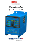
SuperCombi
®
Quick Reference Guide
Rich Electric Co. SuperCombi® Quick Reference Guide V7.19 Copyright 2009
Page 1
Rich Electric Co. SuperCombi® Quick Reference Guide V7.19 Copyright 2009
Page 2
CONTENTS
User Display......................................................................................................................................
Front Panel Display .....................................................................................................4
Front Panel Button Operation....................................................................................6
Main Menu .....................................................................................................................................9
Programming "Operator" ........................................................................................10
Operatoin "Monitor" ................................................................................................13
Operation "Fault Trace" ..........................................................................................16
Operation "Fault History"........................................................................................19
Trouble Shooting Table...............................................................................................................21
This Guide is only a reference for
Basic Operating Instructions and Display Navigation.
For full instructions and programming please refer to the User Manual.
Rich Electric Co. SuperCombi® Quick Reference Guide V7.19 Copyright 2009
Page 3
Front Panel: Display
Front Panel Display
2
1 3
11
12
47
9
PB9
13
10
PB7
PB1 PB8
PB4
PB6
PB2
14
6
16 15 5 8
PB5
PB3
The POWER “rocker” switch is the Master ON / OFF Switch. This switch in the “OFF” position
will terminate all functions of the Combi. This switch in the “ON” position will by default
resume functions previously running when the POWER switch was turned off.
The RUN/STOP button changes the Combi between Standby and Operation Mode.
NOTE: The AC Output is turned OFF when the inverter is Switched OFF at the Master Power
Switch or in Standby mode. The AC Bypass (ATS) is also disabled.
Rich Electric Co. SuperCombi® Quick Reference Guide V7.19 Copyright 2009
Page 4
LED Indicators
LED Name
LED OFF
LED ON
1
AC IN
1. Input voltage normal, and position
> ”transfer Voltage Level”
(180VAC~265VAC)
2. Input voltage frequency range in
No input power
between(45~65Hz)
3. Flashing: Input voltage or frequency
is outside settings.
2
AC
CHARGER
Green: AC Battery charger is working.
3
SOLAR PANEL
4
SOLAR CHARGER Solar module is charging the batteries
5
AC OUT
There is voltage at the “AC OUT”
terminal.
6
INVERTER
Green: Inverter is working.
Green Flashing: Inverter is in Support
mode. (Mains AC power plus the
Inverter power is being used).
7
BATTERY
FLOAT or ABSOR. Or BULK charge
state of battery.
ATS
Green : ATS switch is active AC IN
voltage is being sent directly to AC
OUT terminal
Flashing: AC input is not stable.
8
9
RUN/STOP
Solar module is delivering energy.
1. Solar module
not connected
2. Day or Night /
(cloudy day)
No external solar
charger is connected.
Green: SuperCombi® turn on.
Red: SuperCombi® turn off / standby.
NOTE: Green Blink : Auto-Restart is in use
10
COM./ERR.
Remote control port in communication/in error
Rich Electric Co. SuperCombi® Quick Reference Guide V7.19 Copyright 2009
Page 5
LED Name
LED OFF
LED ON
11
DC GENERATOR
Yellow: DC Generator is connected
and working
12
DC CHARGER
Green: DC Generator is charging
the batteries
13
DC CONTROLLER
Green: DC controller is connected
DC OUT 1
14
DC CONTROLLER
Green: DC controller is connected
DC OUT 2
15
DC OUT 1
Yellow: DC output 1 is supplying
DC power to the DC load
16
DC OUT 2
Yellow: DC output 2 is supplying
DC power to the DC load
Rich Electric Co. SuperCombi® Quick Reference Guide V7.19 Copyright 2009
Page 6
Front Panel Operations
Front Panel: Button Operations
Push Buttons
Push buttons Name
PB1
Description
RUN/STOP SuperCombi® RUN/STOP key
AC Power as Priority
Function Key to return to Main Menu “Operation”
PB2
Before
AC Generator Priority with Dynamic Power Shifting
changing
Function Key to return to Main Menu “Programming” from one
mode to
another, it
Renewable Energy Priority with AC Power Support
has to stop
Function Key to move Cursor to the left digit at
running and
Parameter Edit.
be in STOP
Renewable Energy Priority with AC Power Support
mode.
and AC Charger Backup.
PB3
PB4
PB5
Function Key to move Cursor to the right digit at
Parameter Edit
PB6
DSPL
PB7
ENTER
PB8
PB9
Multi-display select key
Data write-in key
UP(△) △ Increment key Press △ and ▽ keys at the same time to
enable the cursor to move to the left digit from
DOWN (▽)▽Decrement key the current digit.
Four Control Modes Applications:
MODE 1: AC Power as has Priority to Support the AC Load.
MODE 2: AC Generator has Priority to Support the AC Load with Dynamic Power Shifting.
MODE 3: Renewable Energy has Priority to Charge the batteries.
The Combi Inverter has Priority to Support the AC load with AC Power Support.
MODE 4: Renewable Energy has Priority to Charge the batteries with AC Charger Support.
The Combi Inverter has Priority to Support the AC load with AC Power Support.
Rich Electric Co. SuperCombi® Quick Reference Guide V7.19 Copyright 2009
Page 7
Note:
1. When pressing RUN/STOP key, you must hold the key for at least 2 seconds (initial setting)
to activate the RUN or STOP function. This is to avoid any accidental pressing of the
RUN/STOP key. This time can be adjusted, See RUN/STOP Key Hold Time (O2-07) menu.
Refer to page 10.
2. When changing between any of the four modes you must STOP the SuperCombi® and then
press the desired mode key. When pressing MODE 1, MODE 2, MODE 3 or MODE 4 key,
You must hold the key for at least 5 seconds (initial setting) to activate the mode change.
This is to avoid any accidental pressing on the mode keys.
This time can be adjusted, See second MODE Key Hold Time (O2-06) menu. Refer page 10.
3. The beep sound when pressing keys can be enabled or disabled, See Key Pressed Beep Select
(O2-01) menu. Refer page 9.
4. When the front panel is not in use it will go to sleep after a set period of time. (O1-02),
Once any key is pressed, the front panel display will illuminate and the LCD monitor will
resume display. This time can be adjusted, See LCD Display Time Set (02-09) menu.
Refer to page 11.
Note: When the front panel goes to sleep, the LCD Display and LED Indicators are not active
but RUN/STOP indicator remains active.
5. Press △ key to increase the setting value and ▽ key to decrease the setting value.
Press △ and ▽ keys at the same time to enable the cursor to move to the left digit from
the current digit. For example, if the current digit stays in decimal, press △ and ▽ at the
same time for the digit to move to centesimal.
6.
Press
key for 1 second to return to Main Menu “Operation” immediately.
7.
Press
key for 1 second to return to Main Menu “Programming” immediately.
8.
Press
key to move cursor to the left (one digit)
9.
Press
key to move cursor to the right (one digit)
Rich Electric Co. SuperCombi® Quick Reference Guide V7.19 Copyright 2009
Page 8
Main Menu
Press
DSPL
*** Main Menu ***
Operation
*** Main Menu ***
Modified Constants
Press
Press
DSPL
DSPL
*** Main Menu ***
Initialize
*** Main Menu ***
Programming
Press
DSPL
Note: After the set time period (01-02: Key Idle Detect Time) the system will exit any menu screens and
return to the standby display (01-01: Power ON LCD Monitor Select).
Main Menu
There are four options in the Main Menu of the “SuperCombi®” and they are
“Operation”, “Initialize”, “Programming” and “Modified Constants”.
Function
Content
Operation
“SuperCombi®” can monitor AC IN voltage and current, AC
OUT voltage and current, battery voltage, battery current and
ripple voltage in charging and discharging battery and other
extension modules status. This is U (Monitor Group)
constants.
Initialize
Operation Condition Setting Group A (Initialize) Group:
Multi-language setting, constants initialization setting and
constants modification allowed/prohibited setting.
Programming
Constant groups to program (modify) all the constants:
B (General) Group, C (INVERTER) Group,
D (AC CHARGER) Group, E (Aux-relay) Group
F (Solar charger) Group and O (Operator) Group
Modified Constants
Operating the read-out and modification of the constants
group setting which are different from initial setting. Users
can program and modify constants
Note: On any Menu screen, pressing “DSPL” key will return you to the previous Menu.
Rich Electric Co. SuperCombi® Quick Reference Guide V7.19 Copyright 2009
Page 9
Main Menu: Programming “Operator”
Main Menu: Programming
“Operator”
Monitor Select…….
O1-01: Power ON LCD Monitor Select (Standby Display)
Main Menu>Programming>ENT>Operator>ENT>Monitor Select>ENT>
z
z
After power of the SuperCombi® is on, the monitor selections will be showed on
LCD Display, U1-05 Battery Voltage is the initial display shown.
All the constants in U1 Group can be programmed (U1-01~U-26).
O1-02: Key Idle Detect Time
Main Menu>Programming>ENT>Operator>ENT>Monitor Select>ENT>
z
z
Use constant O1-02 to set the idle time when the keyboard is not operated and once
any key is pressed, the display will return to the LCD monitor selection value set in
constant O1-01.
Initial Setting=180 sec, setting range: 10~600 sec.
Rich Electric Co. SuperCombi® Quick Reference Guide V7.19 Copyright 2009
Page 10
Main Menu: Programming “Key Selections”
Key Selections……
O2 Group (Key Selections)
O2-01: Key Pressed Beep Select
Main Menu>Programming>ENT>Operator>ENT>Key Selections>ENT>
Setting
Function
O2-01=0
When keys are pressed, beep sound will not be heard.
O2-01=1
(Initial setting)
When keys are pressed, beep sound will be heard.
O2-02: Elapsed Time Reset
Main Menu>Programming>ENT>Operator>ENT>Key Selections>ENT>
z
Use constant O2-02 to reset elapsed time.
O2-03: Elapsed Time Select
Main Menu>Programming>ENT>Operator>ENT>Key Selections>ENT>
Setting
Function
O2-03=0
(Initial setting)
O2-03=1
The elapsed time started to be counted after power is on.
The elapsed time started to be counted after RUN.
O2-04: SuperCombi® Model
Main Menu>Programming>ENT>Operator>ENT>Key Selections>ENT>
z
This is the model number to be displayed.
O2-06: MODE Key Hold Time
Main Menu>Programming>ENT>Operator>ENT>Key Selections>ENT>
z
z
Use constant O2-06 to set the time it takes to press MODE key to transfer from one
of four modes to another mode. (This has to be done in STOP mode)
Initial setting=5 sec, setting range: 2~10 sec.
Rich Electric Co. SuperCombi® Quick Reference Guide V7.19 Copyright 2009
Page 11
O2-07: RUN/STOP Key Hold Time
Main Menu>Programming>ENT>Operator>ENT>Key Selections>ENT>
z
z
Use constant O2-07 to set the time it takes to press RUN/STOP key to activate its
function.
Initial setting=2 sec, setting range: 2~10 sec.
O2-08: Power ON Auto Run Select
Main Menu>Programming>ENT>Operator>ENT>Key Selections>ENT>
z
Use constant O2-08 to select to auto run manually or automatically.
Setting
Function
O2-08=0
Auto Run is active when pressing Run/STOP key
O2-08=1
(Initial setting)
Auto Run is active when the power is on.
O2-09: LCD Display Idle Time Set
Main Menu>Programming>ENT>Operator>ENT>Key Selections>ENT>
z
z
z
z
When O2-09=0, Display Idle Function is disabled.
Use constant O2-09 to set the idle time when the keypad is not operated and all the
LCD Display and LED Indicators of the SuperCombi® entering the idle mode which
only RUN/STOP indicator is active.
Once any key on the panel is pressed, it will return to the display before Idle status.
Initial setting=10 min, setting range: 0~60 min.
O2-10: System Time Setting
Main Menu>Programming>ENT>Operator>ENT>Key Selections>ENT>
z
Use constant O2-10 to set the system time. Format is hh:mm, “hh” is hour (0~23) and
“mm” is minute (00~59).
O2-11: System Date Setting
Main Menu>Programming>ENT>Operator>ENT>Key Selections>ENT>
z
Use constant O2-11 to set the system date. Format is yy-mm-dd, “yy” is year (0~99),
“mm” is month (01~12), and “dd” is date (01~31).
Rich Electric Co. SuperCombi® Quick Reference Guide V7.19 Copyright 2009
Page 12
Main Menu: Operation “Monitor”
Main Menu: Operation
“Monitor”
U1-01: AC IN Voltage
Main Menu>Operation>ENT>Monitor>ENT>
z
Use U1-01 to monitor the current voltage value of AC IN power in unit of 0.1V.
U1-02: AC IN Current
Main Menu>Operation>ENT>Monitor>ENT>
z
Use U1-02 to monitor the current value of AC IN power in unit of 0.1A.
U1-03: AC OUT Voltage
Main Menu>Operation>ENT>Monitor>ENT>
z
Use constant U1-03 to monitor AC OUT voltage value in unit of 0.1V.
U1-04: AC OUT Current
Main Menu>Operation>ENT>Monitor>ENT>
z
Use constant U1-04 to monitor AC OUT current value in unit of 0.1A .
U1-05: Battery Voltage
Main Menu>Operation>ENT>Monitor>ENT>
z
Use constant U1-05 to monitor the battery voltage in unit of 0.1V.
U1-06: Battery Ripple Voltage
Main Menu>Operation>ENT>Monitor>ENT>
z
Use constant U1-06 to monitor the battery ripple voltage in unit of 0.1V.
U1-07: Battery Current
Main Menu>Operation>ENT>Monitor>ENT>
z
Use constant U1-07 to monitor battery current value in unit of 0.1A.
Rich Electric Co. SuperCombi® Quick Reference Guide V7.19 Copyright 2009
Page 13
U1-08: Control Mode
Main Menu>Operation>ENT>Monitor>ENT>
z
Use constant U1-08 to monitor the current control mode (MODE 1, MODE 2, MODE
3 or MODE 4)
U1-09: Operation Status
Main Menu>Operation>ENT>Monitor>ENT>
z
There are 12 digits to account for each operation status. Please see NOTE 1 in
Chapter 5 of the User Manual.
U1-10: Aux-Relay Status
Main Menu>Operation>ENT>Monitor>ENT>
Use constant U1-10 to monitor the ON/OFF status of 3 sets of Aux-Relay (RY1, RY2,
RY3). Please see NOTE 2 in Chapter 5 of the User Manual.
U1-11: Elapsed Time
Main Menu>Operation>ENT>Monitor>ENT>
z
Use constant U1-11 to monitor the elapsed time after power ON (O2-03=0) or after
RUN (O2-03=1) in unit of 1 hour.
U1-12: Battery Temperature Sensor
Main Menu>Operation>ENT>Monitor>ENT>
z
Use constant U1-12 to monitor the temperature that has been detected by Battery
Temperature Sensor (BTS-3) in unit of 1℃.
U1-13: CPU Version
Main Menu>Operation>ENT>Monitor>ENT>
z
Use constant U1-13 to check the software version 1.
U1-14: System Time
Main Menu>Operation>ENT>Monitor>ENT>
z
Use constant U1-14 to display the current system time. The display format is
year-month-date hour: minutes: sec
Rich Electric Co. SuperCombi® Quick Reference Guide V7.19 Copyright 2009
Page 14
U1-15: Solar Charger Status
Main Menu>Operation>ENT>Monitor>ENT>
z
Use constant U1-15 to monitor solar charger status after solar module is connected to
the extension port (Port C).
U1-16: Solar Supply Current
Main Menu>Operation>ENT>Monitor>ENT>
z
Use constant U1-16 to monitor the solar supply current value in unit of 0.1A.
U1-17: Solar Supply Power
Main Menu>Operation>ENT>Monitor>ENT>
z
Use constant U1-17 to monitor the solar supply power value in unit of 1W.
U1-18: Solar Amp-Hours
Main Menu>Operation>ENT>Monitor>ENT>
z
Use constant U1-18 to monitor solar Amp-Hours value in unit of 1AH.
U1-19: Solar Total Amp-Hours
Main Menu>Operation>ENT>Monitor>ENT>
z
Use constant U1-19 to monitor solar total Amp-Hours value in unit of 1AH.
U1-20: DC/DC Switch Status
Main Menu>Operation>ENT>Monitor>ENT>
z
Use constant U1-20 to monitor DC Generator status after DC Gen module is
connected to the extension port (Port C).
U1-21: Start Batt Voltage
Main Menu>Operation>ENT>Monitor>ENT>
z
Use constant U1-21 to monitor the start Battery voltage value in unit of 0.01V.
U1-22: House Batt Voltage
Main Menu>Operation>ENT>Monitor>ENT>
z
Use constant U1-22 to monitor the House Battery voltage value in unit of 0.01V.
U1-30: DC Load Status
Main Menu>Operation>ENT>Monitor>ENT>
z
Use constant U1-22 to monitor the DC Switch Load output after DC-SW module is
connected to the extension port (Port C).
Rich Electric Co. SuperCombi® Quick Reference Guide V7.19 Copyright 2009
Page 15
U1-35: External ATS Status
Main Menu> Operation>ENT> Monitor>ENT>
z
z
z
Use constant U1-35 to monitor the external ATS communication status. If it shows
“COMM Fault”, the communication between ATS and the CombiPlus is not
established.
When the AC power supply comes from the Master input of AC grid, this constant
will show “Master Input” and the CombiPlus will switch to Mode 1 automatically.
When the AC power supply comes from the Slave input of AC generator, this
constant will show “Slave Input” and the CombiPlus will switch to Mode 2
automatically.
Rich Electric Co. SuperCombi® Quick Reference Guide V7.19 Copyright 2009
Page 16
Main Menu: Operation “Fault Trace”
Main Menu: Operation
“Fault Trace”
U2 Group (Fault Trace)
U2-01: Current Fault
Main Menu>Operation>ENT>Fault Trace>ENT>
z
Use constant U2-01 to monitor the current fault that results in “SuperCombi®”
stopping operating.
U2-02: Last Fault
Main Menu>Operation>ENT>Fault Trace>ENT>
z
Use constant U2-02 to monitor the last fault that has been recorded.
U2-03: AC IN Voltage
Main Menu>Operation>ENT>Fault Trace>ENT>
z
Use constant U2-03 to monitor the AC input voltage value in unit of 0.1V when the
current fault occurs.
U2-04: AC IN Current
Main Menu>Operation>ENT>Fault Trace>ENT>
z
Use constant U2-04 to monitor the AC input current value in unit of 0.1A when the
current fault occurs.
U2-05: AC OUT Voltage
Main Menu>Operation>ENT>Fault Trace>ENT>
z
Use constant U2-05 to monitor the AC output voltage value in unit of 0.1V when the
current fault occurs.
U2-06: AC OUT Current
Main Menu>Operation>ENT>Fault Trace>ENT>
z
Use constant U2-06 to monitor the AC output current value in unit of 0.1A when the
current fault occurs.
Rich Electric Co. SuperCombi® Quick Reference Guide V7.19 Copyright 2009
Page 17
U2-07: Battery Voltage
Main Menu>Operation>ENT>Fault Trace>ENT>
z
Use constant U2-07 to monitor the battery voltage value in unit of 0.1V when the
current fault occurs.
U2-08: Battery Ripple Volt
Main Menu>Operation>ENT>Fault Trace>ENT>
z
Use constant U2-08 to monitor the battery ripple voltage in unit of 0.1V when the
current fault occurs.
U2-09: Battery Current
Main Menu>Operation>ENT>Fault Trace>ENT>
z
Use constant U2-09 to monitor the battery current value in unit of 0.1A when the
current fault occurs.
U2-10: Control Mode
Main Menu>Operation>ENT>Fault Trace>ENT>
z
Use constant U2-10 to monitor what the control mode (MODE 1, MODE 2, MODE 3
or MODE 4) is when the current fault occurs.
U2-11: Operation Status
Main Menu>Operation>ENT>Fault Trace>ENT>
z
Use constant U2-11 to monitor 12 digits which account for each operation status
when the current fault occurs. Please see NOTE 1 in Chapter 5.
U2-12: Aux-Relay Status
Main Menu>Operation>ENT>Fault Trace>ENT>
z
Use constant U2-12 to monitor the ON/OFF status of 3 sets of Aux-Relay (RY1, RY2,
RY3) when the current fault occurs. Please see NOTE 2 in Chapter 5.
U2-13: Elapsed Time
Main Menu>Operation>ENT>Fault Trace>ENT>
z
Use constant U2-13 to monitor the elapsed time after power ON (O2-03=0) or after
RUN (O2-03=1) in unit of 1 hour when the current fault occurs.
Rich Electric Co. SuperCombi® Quick Reference Guide V7.19 Copyright 2009
Page 18
U2-14: Solar Charger Status
Main Menu>Operation>ENT>Fault Trace>ENT>
z
Use constant U2-14 to monitor solar charger status when the current fault occurs.
This constant is only visible when extension port is connected to solar module.
U2-15: Solar Charge Current
Main Menu>Operation>ENT>Fault Trace>ENT>
z
Use constant U2-15 to monitor the solar charge current value in unit of 0.1A when
the current fault occurs.
U2-16: Solar Supply Power
Main Menu>Operation>ENT>Fault Trace>ENT>
z
Use constant U2-16 to monitor the solar supply power value in unit of 1W when the
current fault occurs.
U2-17: Solar Amp-Hours
Main Menu>Operation>ENT>Fault Trace>ENT>
z
Use constant U2-17 to monitor solar Amp-Hours value in unit of 1AH when the
current fault occurs.
U2-18: Solar Total Amp-Hours
Main Menu>Operation>ENT>Fault Trace>ENT>
z
Use constant U2-18 to monitor solar total Amp-Hours value in unit of 1AH when the
current fault occurs.
U2-26: Battery Temperature Sensor
Main Menu>Operation>ENT>Fault Trace>ENT>
z
Use constant U2-26 to monitor the current temperature that has been detected by
Battery Temperature Sensor (BTS-3) in unit of 1℃ when the current fault occurs.
Rich Electric Co. SuperCombi® Quick Reference Guide V7.19 Copyright 2009
Page 19
Main Menu: Operation “Fault History”
Main Menu: Operation
“Fault History”
U3 Group (Fault History)
U3-01: Last Fault
Main Menu>Operation>ENT>Fault History>ENT>
z
Use constant U3-01 to monitor the latest fault stored in the software.
U3-02: Fault Message 2
Main Menu>Operation>ENT>Fault History>ENT>
z
Use constant U3-02 to monitor the most recent second fault stored in the software.
U3-03: Fault Message 3
Main Menu>Operation>ENT>Fault History>ENT>
z
Use constant U3-03 to monitor the most recent third fault stored in the software.
U3-04: Fault Message 4
Main Menu>Operation>ENT>Fault History>ENT>
z
Use constant U3-04 to monitor the most recent fourth fault stored in the software.
U3-05: Elapsed Time 1
Main Menu>Operation>ENT>Fault History>ENT>
z
Use constant U3-05 to monitor the elapsed time before the latest fault occurs.
U3-06: Elapsed Time 2
Main Menu>Operation>ENT>Fault History>ENT>
z
Use constant U3-06 to monitor the elapsed time before the most recent second fault
occurs.
Rich Electric Co. SuperCombi® Quick Reference Guide V7.19 Copyright 2009
Page 20
U3-07: Elapsed Time 3
Main Menu>Operation>ENT>Fault History>ENT>
z
Use constant U3-07 to monitor the elapsed time before the most recent third fault
occurs.
U3-08: Elapsed Time 4
Main Menu>Operation>ENT>Fault History>ENT>
z
Use constant U3-08 to monitor the elapsed time before the most recent fourth fault
occurs.
Rich Electric Co. SuperCombi® Quick Reference Guide V7.19 Copyright 2009
Page 21
Trouble Shooting Table
Trouble Shooting Table
z
z
z
Proceed as follows for a quick detection of common faults.
DC loads must be disconnected from the batteries and the AC loads must be
disconnected from the INVERTER before the INVERTER and/or battery charger
(AC CHARGER) is tested.
Consult your Rich Electric dealer if the fault cannot be resolved.
Problem/Error message
The “SuperCombi®” fails
to operate when power on.
‘Udc-UV’
Battery under volt
‘
‘OL’
Inverter OverLoad
The battery voltage is too
high or too low.
Ensure that the battery
voltage is within the correct
value range.
The battery voltage is low.
Charge the battery or check
the battery connections.
The “SuperCombi®” cuts
out because the battery
voltage is too low.
Charge the battery or check
the battery connections.
The load on the inverter of
“SuperCombi®” is higher
than the normal load.
Reduce the load.
The INVERTER of
“SuperCombi®” cuts out
due to excessive load.
Or “SuperCombi®” has
been Over Loaded and
caused Internal Damage.
Reduce the load.
If Overload warning does
not reset after restart the
“SuperCombi®” will need
to be sent to service for
repair.
The ambient temperature is
too high, or the load is
excessive.
Place the “SuperCombi®”
in a cool and
well-ventilated room, or
reduce the load.
’: blink
OL
Inverter OverLoad
‘OH’
Heatsink Max Temp.
‘
Solution
’: blink
Udc-UV
Battery under volt
‘
Possible Cause
’: blink
Rich Electric Co. SuperCombi® Quick Reference Guide V7.19 Copyright 2009
Page 22
OH
Heatsink Max Temp.
‘Udc-ripple’
Volt Ripple Exceeds
‘
The ambient temperature is
too high, or the load is
excessive.
Place the “SuperCombi®”
in a cool and
well-ventilated room, or
reduce the load.
Voltage ripple on the DC
input exceeds 1.25Vrms
Check the battery cables
and terminals.
Check the battery capacity;
increase it if necessary.
’: blink
Udc-ripple
Volt Ripple Exceeds
Install batteries with a
The INVERTER of
higher capacity.
“SuperCombi®” cuts out as Use shorter and/or thicker
a result of excessive voltage battery cables and reset the
ripple on the DC input
SuperCombi® (Power OFF
and ON again).
“SuperCombi®” will need
‘Udc-OV’
Battery over voltage.
‘
’: blink
Udc-OV
Battery over voltage.
‘Idc-OC’
Over current.
‘
’: blink
Idc-OC
Over current.
Battery charger is not in
normal charging status to
cause battery voltage too
high.
to be sent to service for
repair.
Incorrect battery voltage
connection (12V system but Recheck if the
connected to 24V battery)
SuperCombi® and the
battery voltage is matched.
The actual charge current is
1.5 times larger than the set
current value (D1-08) when
AC CHARGER is
operating.
Stop the Charge mode of
the “SuperCombi®”.
“SuperCombi®” will need
to be sent to service for
repair.
Rich Electric Co. SuperCombi® Quick Reference Guide V7.19 Copyright 2009
Page 23
‘Bat-NG’
Battery Fault
‘
’: blink
Bat-NG
Battery Fault
The charger is not
functioning
The charging time of AC
CHARGER has been over
10 hours and remains in
Bulk Charge mode.
(D1-09=1) shows the
battery is at fault.
Replace the battery banks.
The AC IN voltage or
frequency is out of range.
Ensure that the AC IN
voltage is within the range
220V system:
180VAC~265VAC
110V system:
94VAC~138VAC
And that the frequency
matches the setting.
“SuperCombi®” internal
circuit breaker has tripped.
Reset the internal circuit
breaker.
Incorrect charging current.
Set the charging current at
between (0.1~0.2)× battery
capacity.
The battery is not being
charged fully.
The battery is overcharged.
A defective battery
connection.
Check the battery terminals.
The absorption voltage has
been set to an incorrect
value.
Adjust the absorption
voltage to the correct value.
The float voltage has been
set to an incorrect value.
Adjust the float voltage to
the correct value.
The internal DC fuse is
defective
“SuperCombi®” will need
to be set to service for
repair.
The absorption voltage has
been set to an incorrect
value.
Adjust the absorption
voltage to the correct value.
The float voltage has been
set to an incorrect value.
Adjust the float voltage to
the correct value.
Rich Electric Co. SuperCombi® Quick Reference Guide V7.19 Copyright 2009
Page 24
The battery is overcharged.
Battery charge current drop
to 0 A when the absorption
voltage is reached.
The battery is too small.
Reduce the charging current
or use a battery with a
higher capacity.
A defective battery.
Replace the battery.
The battery is too hot.
Connect a Battery
Temperature Sensor
(BTS-3)
Battery over temperature
(> 50℃)
1. Allow battery to cool
Down.
2. Place battery in a cool
Environment.
3. Check for shorted cells.
1. Unplug Battery
Temperature Sensor
(BTS-3) from
“SuperCombi®”
and power
off the “SuperCombi®”
Battery Temperature Sensor
then wait 5 seconds and
(BTS-3) is faulty
Power on again.
2. If the “SuperCombi®”
AC CHARGE normally,
the BTS-3 is faulty and
needs to be replaced.
Rich Electric Co. SuperCombi® Quick Reference Guide V7.19 Copyright 2009
Page 25
NOTES:
Rich Electric Co. SuperCombi® Quick Reference Guide V7.19 Copyright 2009
Page 26