1
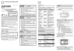
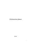
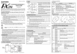
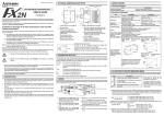
HARDWARE MANUAL FX2N-32DP-IF Profibus-DP Interface Unit FX2N-32DP-IF Profibus-DP Interface Unit Foreword • This manual contains text, diagrams and explanations which will guide the reader in the correct installation and operation of the FX2N-32DP-IF Profibus-DP Interface Unit. It should be read and understood before attempting to install or use the unit. • For operation and setting of FX2N-32DP-IF Profibus-DP Interface Unit, refer to FX2N-32DP-IF User’s Manual. Further information can be found in the FX2N Series Hardware Manual, manuals for special function blocks and Profibus-DP master programmable controllers. • If in doubt at any stage during the installation of the FX2N-32DP-IF Profibus-DP Interface Unit always consult a professional electrical engineer who is qualified and trained to the local and national standards. • If in doubt about operation or use of the FX2N-32DP-IF Profibus-DP Interface Unit please consult the nearest Mitsubishi Electric distributor. • This manual is subject to change without notice. FX2N-32DP-IF Profibus-DP Interface Unit FX2N-32DP-IF Profibus-DP Interface Unit Manual number : JY992D77101 Hardware Manual Manual revision : D Date : April 2002 FX2N-32DP-IF Profibus-DP Interface Unit ii FX2N-32DP-IF Profibus-DP Interface Unit Guidelines for the Safety of the User and Protection of the FX2N-32DP-IF Profibus-DP Interface Unit. This manual provides information for the use of the FX2N-32DP-IF Profibus-DP Interface Unit. The manual has been written to be used by trained and competent personnel. The definition of such a person or persons is as follows: a) Any engineer who is responsible for the planning, design and construction of automatic equipment using the product associated with this manual, should be of a competent nature, trained and qualified to the local and national standards required to fulfill that role. These engineers should be fully aware of all aspects of safety with regards to automated equipment. b) Any commissioning or service engineer must be of a competent nature, trained and qualified to the local and national standards required to fulfill that job. These engineers should also be trained in the use and maintenance of the completed product. This includes being completely familiar with all associated documentation for said product. All maintenance should be carried out in accordance with established safety practices. c) All operators of the completed equipment should be trained to use that product in a safe and coordinated manner in compliance to established safety practices. The operators should also be familiar with documentation which is connected with the actual operation of the completed equipment. Note : The term ‘completed equipment’ refers to a third party constructed device which contains or uses the product associated with this manual. iii FX2N-32DP-IF Profibus-DP Interface Unit Note’s on the Symbols Used in this Manual At various times through out this manual certain symbols will be used to highlight points of information which are intended to ensure the users personal safety and protect the integrity of the equipment. Whenever any of the following symbols are encountered its associated note must be read and understood. Each of the symbols used will now be listed with a brief description of its meaning. Hardware Warnings 1) Indicates that the identified danger WILL cause physical and property damage. 2) Indicates that the identified danger could POSSIBLY cause physical and property damage. 3) Indicates a point of further interest or further explanation. Software Warnings 4) Indicates special care must be taken when using this element of software. 5) Indicates a special point which the user of the associate software element should be aware. 6) Indicates a point of interest or further explanation. iv FX2N-32DP-IF Profibus-DP Interface Unit • Under no circumstances will Mitsubishi Electric be liable responsible for any consequential damage that may arise as a result of the installation or use of this equipment. • All examples and diagrams shown in this manual are intended only as an aid to understanding the text, not to guarantee operation. Mitsubishi Electric will accept no responsibility for actual use of the product based on these illustrative examples. • Please contact a Mitsubishi distributor for more information concerning applications in life critical situations or high reliability. v FX2N-32DP-IF Profibus-DP Interface Unit vi FX2N-32DP-IF Profibus-DP Interface Unit Table of Contents Safety Guidelines ................................................................................ iii 1. Introduction............................................................................................1-1 1.1 Features of the 32DP-IF ...................................................................................... 1-1 1.2 External Dimensions and Each Part Name ......................................................... 1-2 1.2.1 Pin Configuration ....................................................................................................... 1-4 1.3 System Configuration .......................................................................................... 1-5 1.3.1 Connected Monitoring Tools ..................................................................................... 1-6 1.3.2 Connected Extension Blocks and Units .................................................................... 1-7 1.3.3 Configuration Rules Reference ................................................................................. 1-8 2. Mounting and Wiring .............................................................................2-1 2.1 Mounting .............................................................................................................. 2-1 2.1.1 Mounting Arrangements ............................................................................................ 2-1 2.1.2 Mounting.................................................................................................................... 2-3 2.2 Caution for Wiring ................................................................................................ 2-5 2.3 Power Supply ...................................................................................................... 2-9 2.3.1 AC Power Supply Type: FX2N-32DP-IF .................................................................. 2-10 2.3.2 DC Power Supply Type: FX2N-32DP-IF-D .............................................................. 2-12 2.4 Profibus-DP Network ......................................................................................... 2-14 2.5 Wiring for Connecting to Extension Blocks/Units and Special Function Blocks 2-16 vii FX2N-32DP-IF Profibus-DP Interface Unit 3. Specifications ........................................................................................3-1 3.1 General Specifications......................................................................................... 3-1 3.2 Power Supply Specifications ............................................................................... 3-2 3.3 Performance Specifications ................................................................................. 3-3 4. Address Setting .....................................................................................4-1 4.1 Setting the Address ............................................................................................. 4-1 4.2 Example Address Setting .................................................................................... 4-2 5. Diagnostics............................................................................................5-1 5.1 Preliminary Checks.............................................................................................. 5-1 5.2 Check the Status of the LEDs of the 32DP-IF ..................................................... 5-2 Appendix A Further Information Manual Lists.............................................................. A-1 Appendix B Update History of FX2N-32DP-IF and GSD File ....................................... B-1 viii FX2N-32DP-IF Profibus-DP Interface Unit 1. Introduction 1 Introduction The FX2N-32DP-IF(-D) Profibus-DP Interface Unit (called “32DP-IF” hereinafter) can be used to connect FX2N/FX0N series extension units/blocks and special function units/blocks directly to an existing Profibus-DP network. The 32DP-IF provides an intelligent slave function for decentralized control applications. Digital and analog data from a Profibus-DP master CPU (called “DP-master” hereinafter) can be sent and received to/from any of the supported I/O blocks and special function blocks. 1.1 Features of the 32DP-IF Using the 32DP-IF the FX2N/FX0N series extension units/blocks and special function units/ blocks can exchange data with any DP-master. • Up to 256 I/O points and/or up to 8 special function blocks can be connected to the 32DP-IF. However, adjust total control I/O points to 256 or less. See section 1.3. • The slave address of the 32DP-IF is adjusted by DIP switches. See chapter 4. • The 32DP-IF can be connected to a Profibus-DP network via a standard 9-pin D-SUB connector and a shielded twisted pair cable complying with EN50170. Optional glassfiber adapters are supported by the 32DP-IF and are available from other vendors. See chapter 2. • An FX-20P-E or personal computer can be used to monitor the status of the 32DP-IF and the data exchanged with the Profibus network. For operating instructions of the FX-20P-E or personal computer, refer to their respective operation manuals. For device numbers and explanation, refer to the FX2N-32DP-IF User’s Manual. 1-1 FX2N-32DP-IF Profibus-DP Interface Unit External Dimensions and Each Part Name Dimensions: mm (inches) Accessory: GSD files (FD: 1 piece) MASS (Weight): Approx. 0.4 kg (0.88 lbs) Figure 1.1: External Dimensions F X 2 N - 3 2 D P - IF ( A C P o w e r S u p p ly T y p e ) L N c ) b ) C O M F X 2 N - 3 2 D P - IF - D ( D C P o w e r S u p p ly T y p e ) 2 4 + e ) d ) f ) 2 4 + g ) m ) 2 4 - h ) R U N S T O P C O M 2 4 + a ) P O W E R R U N B F D IA F X 2 N k ) n ) O N O F F l ) -3 2 D P -IF 1 0 5 (4 .1 3 ") N 9 0 (3 .5 4 ") 9 8 (3 .8 6 ") L 6 4 3 2 1 6 8 4 2 1 1.2 Introduction 1 6 7 (2 .6 4 ") 7 5 (2 .9 5 ") i ) j ) 8 7 (3 .4 3 ") 1-2 FX2N-32DP-IF Profibus-DP Interface Unit Introduction 1 a) Profibus-DP communication port (D-SUB 9 pin) b) Power supply terminals (screw terminal: M3.5 (0.14")) FX2N-32DP-IF (AC power supply type): L, N and grounding terminal FX2N-32DP-IF-D (DC power supply type): 24+, 24- and grounding terminal c) Direct mounting hole (2-φ4.5 (0.18")) d) 24 V DC power terminal (screw terminal: M3.5 (0.14")) FX2N-32DP-IF-D does not have this terminal. e) RUN/STOP switch: When this switch is in the RUN position, the 32DP-IF will exchange data with extension units/blocks and special function blocks. If this switch is in the STOP position, the 32DP-IF will exchange only input data with extension units/blocks. f) Communication port for FX-20P-E or personal computer g) POWER LED: ON when power is supplied. h) RUN LED: ON when 32DP-IF is exchanging data with extension units/blocks and special function blocks. i) BF LED: ON when a communication error is detected (No data exchange). j) DIA LED: ON when diagnostic data is detected. k) Hook for DIN rail mounting l) DIP switches for slave address of this unit m) Extension port n) Groove for DIN rail mounting (DIN rail width: 35 mm (1.38")) 1-3 FX2N-32DP-IF Profibus-DP Interface Unit Pin Configuration The connector is a 9-pin D-SUB type and the pin configuration is shown below. Figure 1.2: Pin Layout 9-pin D-SUB Table 1.1: Pin Configuration Signal Meaning 3 RXD/TXD-P Receive/transmit-Data-P 4 RTS Request to send 5 DGND Data Ground 6 VP Voltage-Plus 8 RXD/TXD-N Receive/transmit-Data-N 2 7 3 8 4 9 5 Connector Assigned Not assigned 1,2,7,9 NC Pin not assigned 1 6 1.2.1 Introduction 1 1-4 FX2N-32DP-IF Profibus-DP Interface Unit 1.3 Introduction 1 System Configuration Figure 1.3: System Configuration DP-master Profibus-DP network Slave or DP-master *1 FX2N-32DP-IF Profibus-DP interface unit *2 Slave or DP-master *1 Extension I/O units/blocks and special function blocks *3 *1 The units at each end of the Profibus-DP network must have a terminating resistor. This will either be in the master, slave unit or in the Profibus connector. *2 For connecting a monitoring tool, refer to subsection 1.3.1 *3 For connecting units/blocks, refer to subsection 1.3.2. Caution The parameter data of the 32DP-IF must be set correctly in the DP-master, if the parameter data is not correct, the operation of the module may be affected. For parameter of 32DP-IF, refer to FX2N-32DP-IF User’s Manual. 1-5 FX2N-32DP-IF Profibus-DP Interface Unit 1.3.1 Introduction 1 Connected Monitoring Tools An FX-20P-E or personal computer can be used to monitor the 32DP-IF and the data exchanged with the Profibus. For operating instructions of the FX-20P-E or personal computer, refer to their respective operation manuals. For device numbers and explanation, refer to the FX2N-32DP-IF User’s Manual. Connecting cable is same as FX2N MPU. Table 1.2: Connected Programming Tools Monitoring Tools Description FX-20P-E Personal Computer (MELSEC MEDOC PLUS) Device monitor Note; For monitoring the 32DP-IF with a personal computer the PLC setting must be adjusted as for the FX series PLC type. 1-6 FX2N-32DP-IF Profibus-DP Interface Unit 1.3.2 Introduction 1 Connected Extension Blocks and Units Table 1.3: Extension I/O Blocks/Units and Special Function Blocks Unit Type Type Name FX2N-32ER-ES/UL, FX2N-32ET-ESS/UL, Model: V1.00 ∼ FX2N-48ER-ES/UL, FX2N-48ET-ESS/UL GSD file:V1.00 ∼ FX2N-48ER-UA1/UL Extension Units (Digital I/O Units) Model: V2.10 ∼ FX2N-48ER-DS, FX2N-48ET-DSS GSD file:V2.10 ∼ FX2N Series Extension Blocks (Digital I/O Blocks) Supported Version Model: V1.00 ∼ FX2N-16EX-ES/UL, FX2N-16EYR-ES/UL, GSD file:V1.00 ∼ FX2N-16EYT-ESS/UL FX0N-8EX-UA1/UL, FX0N-8EX-ES/UL, FX0N-16EX-ES/UL, Model: V1.00 ∼ FX0N-8ER-ES/UL, FX0N Series GSD file:V1.00 ∼ FX0N-8EYR-ES/UL, FX0N-8EYT-ESS/UL, FX0N-16EYR-ES/UL, FX0N-16EYT-ESS/UL Model: V1.00 ∼ FX2N-4DA, FX2N-4AD, FX2N-4AD-PT, GSD file:V1.00 ∼ FX2N-4AD-TC Special Function Blocks/Units FX2N-2DA, FX2N-2AD, FX0N-3A, FX2N-1HC, Model: V1.10 ∼ FX2N-1PG, FX2N-10GM, FX2N-20GM, GSD file:V1.10 ∼ FX2N-32ASI-M, FX2N-232IF Model: V2.10 ∼ FX2N-8AD, FX2N-2LC, FX2N-10PG GSD file:V2.10 ∼ 1-7 FX2N-32DP-IF Profibus-DP Interface Unit 1.3.3 Introduction 1 Configuration Rules Reference Further information for the Configuration Rules can be found in FX2N-32DP-IF User’s Manual. 1) Total I/O points on the system ≤ 256 points The following (a ~ c) I/O points must be a total of 256 points or less. For I/O point allocation for each extension unit/block and each special function unit/block, refer to FX2N-32DP-IF User’s Manual. a) Count I/O points for the extension units/blocks (including additional occupied points). b) Count the occupation I/O points for special function units/blocks. A 32DP-IF can connect a Maximum of 8 special function blocks. c) Count I/O points for FX2N-32ASI-M’s active slaves. 2) Supply 24V DC (total internal and service power supply) and 5V DC to the extnsion I/O blocks and special function units/blocks from the 32DP-IF or exteniosn I/O units. If 24V DC and 5V DC is not supplied to both special function blocks and extension I/O blocks, the hardware configuration will need to be changed. For power consumption, refer to FX2N-32DP-IF User’s Manual. 3) Total exchange data length ≤ 200 bytes (or DP master’s maximum exchange data length if ≤ 200 bytes) The following (a, b) exchange data must be a total of 200 bytes (or DP master’s maximum exchange data length if ≤ 200 bytes) or less. For exchange data length, refer to FX2N-32DP-IF User’s Manual. a) Total exchange data for extension I/O units/blocks. b) Total exchange data for special function units/blocks. 1-8 FX2N-32DP-IF Profibus-DP Interface Unit Introduction 1 4) Total user parameter length ≤ 193 bytes (or DP master’s maximum user parameter length if ≤ 193 bytes) The user parameter length must be a total of 193 bytes (or DP master’s maximum exchange data length if ≤ 193 bytes) or less. For user parameter length, refer to FX2N-32DP-IF User’s Manual. 1-9 FX2N-32DP-IF Profibus-DP Interface Unit Introduction 1 MEMO 1-10 FX2N-32DP-IF Profibus-DP Interface Unit 2. Mounting and Wiring 2.1 Mounting 2.1.1 Mounting Arrangements Mounting and Wiring 2 To prevent a rise in temperature, mount the units to the back walls. Never mount them to the floor, ceiling or side wall of an enclosure. Figure 2.1: Mounting Location FX2N-16EYT -ESS/UL FX2N-16EX -ES/UL FX2N-32DP-IF FX2N-4AD > 50 mm (1.97") FX2N-4DA > 50 mm (1.97") > 50 mm (1.97") > 50 mm (1.97") 2-1 FX2N-32DP-IF Profibus-DP Interface Unit Mounting and Wiring 2 Figure 2.2: Mounting Arrangement 2-2 FX2N-32DP-IF Profibus-DP Interface Unit 2.1.2 Mounting and Wiring 2 Mounting Mounting method for the 32DP-IF is DIN rail mounting or direct wall mounting. 1) DIN Rail Mounting - Align the upper side of the DIN rail mounting groove of the 32DP-IF with a DIN rail*1 (•), and push it on the DIN rail(‚). See Figure 2.3. - When removing the 32DP-IF from the DIN rail, the hook for DIN rail is pulled (ƒ), and the 32DP-IF is removed („). See Figure 2.4. Figure 2.3: Attach to DIN Rail 2-3 FX2N-32DP-IF Profibus-DP Interface Unit Mounting and Wiring 2 Figure 2.4: Remove from DIN Rail *1 Uses DIN 46277 <35mm (1.38")> 2) Direct Mounting to Back Walls The 32DP-IF can be mounted with M4 screws by using the direct mounting holes. An interval space between each unit of 1 ~ 2 mm is necessary. For mounting hole position of 32DP-IF, refer to section 1.2. Further information about extension I/O units/blocks can be found in the FX2N Hardware Manual. Further information about special function units/blocks can be found in each manual. 2-4 FX2N-32DP-IF Profibus-DP Interface Unit 2.2 Mounting and Wiring 2 Caution for Wiring 1) Do not lay signal cable near to either high voltage power cabling or cabinet housing along the same trunking duct. Effects of noise or surge induction may occur. Keep signal cables of more than 100 mm (3.94") from these power cables. 2) Ground the shield wire or the shield of a cable at one point on the module. Do not, however, ground at the same point as high voltage lines. 3) Cut off all phases of power source before installation or performing wiring work in order to avoid electric shock or damage to the product. 4) Replace the provided terminal cover before supplying power and operating the unit after installation or wiring work, in order to avoid electric shock. 5) To connect the 32DP-IF to a Profibus-DP network should be used only the Profibus connectors and shielded twisted-pair cable complying with EN50170. 6) The power supply of the extension units/blocks and the special function units/blocks should be starting-up at the same time or earlier than it with 32DP-IF. 7) DO NOT use the “●” terminal of the 32DP-IF. 8) “24+” and “24-” terminal are not reversible. If “24+” and “24-” terminal are reversed, the units/block may be serious damaged. 2-5 FX2N-32DP-IF Profibus-DP Interface Unit Mounting and Wiring 2 9) The terminal tightening torque is 0.5 to 0.8 N•m. Tighten securely to avoid malfunction. 10)The terminal screws of FX2N-32DP-IF is M3.5 (0.14"). However, the terminal screws of the FX0N, FX2N Series extension I/O units/blocks and special function units/blocks are M3 (0.12"). The crimp style terminal (see drawing) suitable for use with these screws should be fitted to the cable for wiring. When installing 1 or 2 crimp terminal to a terminal, see each explanation below. However, 3 crimp terminals or more cannot be installed to a single terminal. 2-6 FX2N-32DP-IF Profibus-DP Interface Unit Mounting and Wiring 2 a) Handle the crimp terminal of the following size as and when 1 wire is used per terminal. Refer to Figure 3.3 for installation instructions. Figure 2.5: Crimp Terminal for M3.5 Screws 6.8 mm (0.27" ) or less φ 3.7 (0.15") φ 3.7 (0.15") 6.8 mm (0.27") or less Figure 2.6: Crimp Terminal for M3 Screws 6.2 mm (0.24" ) or less φ 3.2 (0.13") φ 3.2 (0.13") 6.2 mm (0.24") or less Figure 2.7: Installing 1 wire Per Terminal Terminal screw Crimp terminal Terminal 2-7 FX2N-32DP-IF Profibus-DP Interface Unit Mounting and Wiring 2 b) Handle the crimp terminal of the following size as and when 2 wires are used per terminal. Refer to Figure 3.6 for installation instructions. Figure 2.8: Crimp Terminal for M3.5 Screws 6.8 mm (0.27" ) or less φ 3.7 (0.15") φ 3.7 (0.15") 6.8 mm (0.27") or less 6.0 mm or more 6.0 mm or more Figure 2.9: Crimp Terminal for M3 Screws 6.2 mm (0.24" ) or less φ 3.2 (0.13") φ 3.2 (0.13") 6.2 mm (0.24") or less 6.3 mm or more 6.3 mm or more Figure 2.10:Installing 2 Wires Per Terminal Terminal screw Crimp terminal Terminal 2-8 FX2N-32DP-IF Profibus-DP Interface Unit 2.3 Mounting and Wiring 2 Power Supply Further information for the extension unit’s wiring can be found in the FX2N Series Hardware Manual. Further information for special function units/blocks can be found in their respective manual. For wiring of grounding, refer to Section 2.4. 2-9 FX2N-32DP-IF Profibus-DP Interface Unit 2.3.1 Mounting and Wiring 2 AC Power Supply Type: FX2N-32DP-IF When wiring a 32DP-IF and extension I/O units/blocks, the connection method is identical to a FX2N series PLC. Further information can be found in the FX2N-32DP-IF User’s Manual and FX2N Series Hardware Manual. • Supply both FX2N-32DP-IF and extension I/O units from the same AC power source. • Connect “COM” terminal on the 32DP-IF to the “0V” terminal on the extension unit. • For ground wiring, refer to Section 2.4. 2-10 FX2N-32DP-IF Profibus-DP Interface Unit Mounting and Wiring 2 Figure 2.11:AC Power Supply Type: FX2N-32DP-IF Grounding Ref. Section 2.4 100~ 240V AC L Service power supply Fuse Service power supply N MC*1 Start Emegency stop Switch Switch MC MC MC L N 2 C 4 O + M S / S X 0 0 0 X 0 0 1 Extension I/O Block FX2N-32DP-IF (Source Input) Power supply for AC loads L N 2 4 0 + V S X X / S 0 1 Extension I/O Unit <AC Power Supply Type> C Y Y O 0 0 (Source Input M 0 0 Relay Output) 1 0 1 Power supply for AC loads *1 Magnetic contact safety circuit 2-11 FX2N-32DP-IF Profibus-DP Interface Unit 2.3.2 Mounting and Wiring 2 DC Power Supply Type: FX2N-32DP-IF-D When wiring a 32DP-IF and extension I/O units/blocks, the connection method is identical to a FX2N series PLC. Further information can be found in the FX2N-32DP-IF User’s Manual and FX2N Series Hardware Manual. • Supply both FX2N-32DP-IF-D and extension I/O units/blocks from the same DC power source. • For ground wiring, refer to Section 2.4. 2-12 FX2N-32DP-IF Profibus-DP Interface Unit Mounting and Wiring 2 Figure 2.12:DC Power Supply Type: FX2N-32DP-IF-D 24V DC Fuse MC*1 Grounding Ref. Section 2.4 Emegency Start stop Switch Switch MC MC MC 2 2 4 4 + FX2N -32DP-IF-D Power supply for DC loads *2 S / S X 0 0 0 X 0 0 1 Extension I/O Block (Source Input) 2 4 0 V V *2 S X X / S 0 1 Extension I/O Unit <DC Power Supply Type> C Y Y O 0 0 (Source Input M 0 0 Relay Output) 1 0 1 Power supply for AC loads *1 Magnetic contact safety circuit *2 DO NOT connect wire to this terminal. 2-13 FX2N-32DP-IF Profibus-DP Interface Unit 2.4 Mounting and Wiring 2 Profibus-DP Network To connect the 32DP-IF to a Profibus-DP network should be used only the Profibus connectors and shielded twisted-pair cable complying with EN50170. Please use terminating resistors and Profibus connectors as shown in the DP-master manual and Profibus connector manual. The 32DP-IF does not have a terminating resistance built-in. Note: Noise Prevention For noise prevention please attach at least 50mm (1.97”) of the shielded twisted-pair cable along the grounding plate to which the ground terminal is connected. 2-14 FX2N-32DP-IF Profibus-DP Interface Unit Mounting and Wiring 2 Figure 2.13:Connect to Profibus-DP Network 32DP-IF ‚ L(24+) N(24-) • ‡ ƒ „ … † Table 2.1: Connect to Profibus-DP Network Ref. Description ① Power source for 32DP-IF (Refer to section 3.2) ② Grounding terminal in 32DP-IF ③ Profibus connector (Refer to Figure 3.10) ④ Grounding plate ⑤ For noise Prevention please attach at least 50mm (1.97”) of the shielded twisted-pair cable along the grounding plate to which the ground terminal is connected. ⑥ Grounding resistance of 100Ω or less ⑦ Shielded twisted-pair cable complying with EN50170 to Profibus-DP network 2-15 FX2N-32DP-IF Profibus-DP Interface Unit Mounting and Wiring 2 Figure 2.14:Profibus Connection S h ielded tw isted -p air cab le to P rofib us-D P ne tw o rk F X 2N -3 2D P -IF P ro fibu s-D P In te rfa ce U nit 2.5 Wiring for Connecting to Extension Blocks/Units and Special Function Blocks Further information can be found in FX2N-32DP-IF User’s Manual, FX2N Hardware Manual and each manual for using special function unit/block. 1) AC Power Supply Type (FX2N-32DP-IF) a) Supply both FX2N-32DP-IF and extension I/O units from the same AC power source. b) Connect “COM” terminal on the FX2N-32DP-IF to the “0V” terminal on the extension units. For extension unit’s wiring, refer to FX2N Series Hardware Manual. 2) DC Power Supply Type FX2N-32DP-IF-D) Supply both FX 2N-32DP-IF-D and extension I/O units/blocks from the same DC power source. 2-16 FX2N-32DP-IF Profibus-DP Interface Unit 3. Specifications 3.1 General Specifications Specifications 3 Table 3.1: General Specifications Item Description Operating Temperature 0 ~ 55°C (32 to 131°F) Storage Temperature -20 ~ 70°C (-4 to 158°F) Operating Humidity 35 ~ 85% Relative Humidity, No condensation Storage Humidity 35 ~ 90% Relative Humidity, No condensation Vibration Resistance - Direct Mounting Vibration Resistance - DIN rail Mounting Conforms to EN68-2-6; 10 ~ 57Hz: 0.075mm Half Amplitude 57 ~ 150Hz: 9.8m/s2 Acceleration Sweep Count for X, Y, Z: 10 times (80 min in each direction) Conforms to EN68-2-6; 10 ~ 57Hz: 0.035mm Half Amplitude 57 ~ 150Hz: 4.9m/s 2 Acceleration Sweep Count for X, Y, Z: 10 times (80min in each direction) Shock Resistance Conforms to EN68-2-27: 147m/s2 Acceleration, Action Time: 11ms 3 times in each direction X, Y, and Z Noise Immunity 1,000Vp-p, 1microsecond, 30 ~ 100Hz, tested by noise simulator FX2N-32DP-IF Dielectric Withstand Voltage FX2N-32DP-IF-D 1,500V AC > 1 min, tested between all points, terminals and ground 500V AC > 1 min, tested between all points, terminals and ground Insulation Resistance 5MΩ > at 500V DC, tested between all points, terminals and ground Grounding Grounding resistance is 100Ω or less Complies with UL508 3-1 FX2N-32DP-IF Profibus-DP Interface Unit 3.2 Specifications 3 Power Supply Specifications Table 3.2: Power Supply Specifications Description Item Power Supply FX2N-32DP-IF (AC Power Supply Type) 100 ~ 240 V AC +10% -15%, 50/60 Hz FX2N-32DP-IF-D (DC Power Supply Type) 24 V DC +20% -30% 5 ms at 24 V DC 10 ms at 100 V AC Max. Allowable Momentary (< 10 ms, 32DP-IF = RUN continue, (< 5 ms, 32DP-IF = RUN continue, Power Failure Period > 10 ms, 32DP-IF = power down) > 5 ms, 32DP-IF = power down) Fuse (size) Rating 3.15 A <φ 5 × 20 mm (0.2 × 0.79 inches), Time lag fuse> 1A <φ 5 × 20 mm (0.2 × 0.79 inches), Time lag fuse> In-rush Current 100 V AC Max. 40 A < 5 ms, 200 V AC Max. 60 A < 5 ms 24 V DC Max. 30 mA < 5 ms Power Consumption 30 VA 14W 24 V DC Service Supply 500 mA Max. 5 V DC Bus Supply 220 mA - 3-2 FX2N-32DP-IF Profibus-DP Interface Unit 3.3 Specifications 3 Performance Specifications Table 3.3: Performance Specifications Items Specifications Maximum Number of Controllable I/O Points Maximum 256 points (see section 1.3) Transmission data (Exchange data length) Max.200 bytes, total of sent and received during one bus cycle. (input: Max. 200 bytes, output: Max. 200 bytes) Transmission Type Bus network Port 9 pin D-SUB Port for Profibus-DP network 8 pin mini DIN Port for FX-20P-E or personal computer (MELSEC MEDOC PLUS) 9.6k, 19.2k, 45.45k, 93.75k 1,200 m (3,937') Supported Baud 187.5k Rates (bps) and 500k Bus Length LED Indicators 1,000 m (3,281') 400 m (1,312') 1.5M 200 m (656') 3M, 6M, 12M 100 m (328') POWER LED ON when power is supplied. RUN LED ON when 32DP-IF is exchanging data with extension I/O blocks/ units and special function blocks. BF LED ON when a communication error is detected. (No data exchange) DIA LED ON when notice of diagnostic data is detected. 3-3 FX2N-32DP-IF Profibus-DP Interface Unit Specifications 3 MEMO 3-4 FX2N-32DP-IF Profibus-DP Interface Unit 4. Address Setting 4.1 Setting the Address Address Setting 4 The slave address of 32DP-IF for Profibus network is set by the ON/OFF configuration of DIP switches. Slave address setting range is 0 ~ 126. When 32DP-IF’s power supply is turned ON, the slave address is the sum total of these DIP switch values. 64 32 16 8 4 2 1 Figure 4.1: DIP Switches T his is the D IP sw itch valu e. ON T his D IP sw itch is no t used fo r th e a dd re ss se tting . P lea se le ave in th e O F F p ositio n. O FF T he se D IP sw itche s a re O F F . T his D IP sw itch is O N . Note: If the address of 32DP-IF is changed, the 32DP-IF must be turned OFF and ON again in order to activate the new address. 4-1 FX2N-32DP-IF Profibus-DP Interface Unit Example Address Setting If slave address of 32DP-IF is set to “22”, the DIP switches are as shown below. Figure 4.2: Address Setting 64 32 16 8 4 2 1 4.2 Address Setting 4 ON OFF 4-2 FX2N-32DP-IF Profibus-DP Interface Unit 5. Diagnostics 5.1 Preliminary Checks Diagnostics 5 1) Check “POWER LED”. If this is OFF, please see section 5.2. 2) Check that the slave address is the same at the 32DP-IF and the DP-master configuration. If the slave address is not the same in the 32DP-IF and in the DP-master, change this address to match in both modules. 3) Check that the parameter data of 32DP-IF are set correctly in the DP-master. If the parameter data of the 32DP-IF are not set correctly in the DP-master, communication over the Profibus-DP network may be affected. 4) Check whether the network wiring and/or the cables for the extension blocks/units are properly connected to the 32DP-IF. 5) Check that the system configuration rules have not been exceeded, i.e. the number of special function blocks does not exceed 8 and control I/O of 32DP-IF is 256 or less. 6) Put RUN/STOP switch on the 32DP-IF into RUN. 5-1 FX2N-32DP-IF Profibus-DP Interface Unit 5.2 Diagnostics 5 Check the Status of the LEDs of the 32DP-IF If the 32DP-IF does not seem to operate normally, check the following items. For error flags, error codes, and device explanation, refer to FX2N-32DP-IF User’s Manual. 1) Check the status of the “POWER LED”. Table 5.1: POWER LED Check Status Description Lit Power source is OK. Unlit Possible AC or DC power failure, check power line and power source. 2) Check the status of the “RUN LED” Table 5.2: RUN LED Check Status Description Lit The 32DP-IF will exchange data with extension units/blocks and special function blocks. Unlit The 32DP-IF will exchange only input data with extension units/blocks. Check position of the RUN/STOP switch. If the switch is in the STOP position, change to RUN. 5-2 FX2N-32DP-IF Profibus-DP Interface Unit Diagnostics 5 3) Check the status of the “BF LED” Table 5.3: BF LED Check Status Description Lit Check D8024. If D8024 does not show a stable baud rate (i.e. always changing) then check DP-network cables. Check M8004. If M8004 is ON, refer to FX2N-32DP-IF User’s Manual. Unlit 32DP-IF will exchange data with profibus-DP network. 4) Check the status of the “DIA LED” Table 5.4: DIA LED Check Status Description Lit Check status of M8004, and DP-master setting. If M8004 is ON, refer to FX2N-32DP-IF User’s Manual. Unlit Diagnostic data is not detected. 5-3 FX2N-32DP-IF Profibus-DP Interface Unit Diagnostics 5 MEMO 5-4 FX2N-32DP-IF Profibus-DP Interface Unit Appendix A: Appendix A: Further Information Manual Lists Table A-1: Further Information Manual Lists Manual name Manual No. Description FX2N Series Programmable Controllers Hardware Manual This manual contains explanations for wiring, JY992D66301 installation and specification, etc. about FX2N Series programmable controller. FX0/FX0N Series Programmable Controllers Hardware Manual This manual contains explanations for wiring, JY992D47501 installation and specification, etc. about FX0 and FX0N Series programmable controllers. FX2N-32DP-IF Profibus-DP Interface Unit User’s Manual This manual contains explanations for wiring, installation, specification and BFM allocation, etc. JY992D79401 about FX2N-32DP-IF Profibus-DP Interface Unit. However, the hardware manual’s text is already contained in the user’s manual. FX2N-2DA Special Function Block User’s Guide This manual contains explanations for wiring, JY992D74901 installation, specification and BFM allocation, etc. about FX2N-2DA special function block. FX2N-2AD Special Function Block User’s Guide This manual contains explanations for wiring, JY992D74701 installation, specification and BFM allocation, etc. about FX2N-2AD special function block. FX0N-3A Special Function Block User’s Guide This manual contains explanations for wiring, JY992D49001 installation, specification and BFM allocation, etc. about FX0N-3A special function block. A-1 FX2N-32DP-IF Profibus-DP Interface Unit Table A-1: Appendix A: Further Information Manual Lists Manual name Manual No. Description FX2N-4DA Special Function Block User’s Guide This manual contains explanations for wiring, JY992D65901 installation, specification and BFM allocation, etc. about FX2N-4DA special function block. FX2N-4AD Special Function Block User’s Guide This manual contains explanations for wiring, JY992D65201 installation, specification and BFM allocation, etc. about FX2N-4AD special function block. FX2N-4AD-PT Special Function Block User’s Guide This manual contains explanations for wiring, JY992D65601 installation, specification and BFM allocation, etc. about FX2N-4AD-PT special function block. FX2N-4AD-TC Special Function Block User’s Guide This manual contains explanations for wiring, JY992D65501 installation, specification and BFM allocation, etc. about FX2N-4AD-TC special function block. FX2N-1HC Special Function Block User’s Guide This manual contains explanations for wiring, JY992D65401 installation, specification and BFM allocation, etc. about FX2N-1HC special function block. FX-1PG/FX2N-1PG Pulse Generation Unit User’s Manual This manual contains explanations for wiring, JY992D65301 installation, specification and BFM allocation, etc. about FX-1PG/FX2N-1PG Pulse Generation Unit. FX2N-10GM User’s Guide This manual contains explanations for specification about FX2N-10GM Positioning Control Unit. JY992D77701 However, the user’s guide’s text is already contained in the hardware/programming manual. A-2 FX2N-32DP-IF Profibus-DP Interface Unit Table A-1: Appendix A: Further Information Manual Lists Manual name Manual No. Description FX2N-20GM User’s Guide This manual contains explanations for specification about FX2N-20GM Positioning Control Unit. JY992D77601 However, the user’s guide’s text is already contained in the hardware/programming manual. FX2N-10GM, FX2N-20GM Hardware/Programming Manual This manual contains explanations for wiring, installation, specification, parameter, instruction and BFM allocation, etc. about FX2N-10GM and JY992D77801 FX2N-20GM Positioning Control Unit. However, these user’s guide’s text is already contained in the hardware/programming manual. FX2N-32ASI-M AS-interface Master Block User’s Manual This manual contains explanations for wiring, JY992D76901 installation, specification and BFM allocation, etc. about FX2N-32ASI-M AS-interface Master Block FX2N-232IF RS-232C Interface Block Hardware Manual This manual contains explanations for wiring, installation and specification, etc. about FX2N-232IF JY992D73501 RS-232C Interface Block. For BFM allocation and example program, please see FX Communication (RS232C, RS485) User’s Manual. FX2N-8AD Analog Input Block User’s Manual This manual contains explanation for wiring, JY992D86001 installation, specification and BFM allocation, etc. about FX2N-8AD special function block. FX2N-2LC User’s Manual This manual contains explanation for wiring, JY992D85801 installation, specification and BFM allocation, etc. about FX2N-2LC special function block. A-3 FX2N-32DP-IF Profibus-DP Interface Unit Table A-1: Appendix A: Further Information Manual Lists Manual name Manual No. Description FX2N-10PG User’s Manual This manual contains explanation for wiring, JY992D85801 installation, specification and BFM allocation, etc. about the FX2N-10PG Pulse Generation Unit. FX Communication (RS232C, RS485) User’s Manual This manual contains explanations for N:N network, parallel link and computer link no protocol JY992D69901 communication (RS instruction and FX2N-232IF RS232C interface block) about FX family PLC. MELSEC ProfiMap Configuration System for Open Networks Software Manual - This manual contains explanations for operation of MELSEC ProfiMap Configuration System for Open Networks Software. A-4 FX2N-32DP-IF Profibus-DP Interface Unit Appendix B: Appendix B: Update History of FX2N-32DP-IF and GSD File Table B-1: Update History of FX2N-32DP-IF and GSD File Version 32DP-IF Hardware GSD File Contents V1.00 V1.00 First Product Supports the following unit / block. • Special function blocks: FX2N-4AD, FX2N-4AD-TC, FX2N-4AD-PT, FX2N-4DA • Extension units: FX2N-32ER-ES/UL, FX2N-32ET-ESS/UL, FX2N-48ER-ES/UL, FX2N-48ET-ESS/UL FX2N-48ER-UA1/UL • Extension blocks: FX2N-16EX-ES/UL, FX2N-16EYR-ES/UL, FX2N-16EYT-ESS/UL, FX0N-8EX-UA1/UL, FX0N-8EX-ES/UL, FX0N-8ER-ES/UL, FX0N-8EYR-ES/UL, FX0N-8EYT-ESS/UL, FX0N-16EX-ES/UL, FX0N-16EYR-ES/UL, FX0N-16EYT-ESS/UL V1.10 V1.10 Supports FX0N-3A, FX2N-2AD, FX2N-2DA, FX2N-1HC, FX2N-1PG, FX2N-10GM, FX2N-20GM, FX2N-32ASI-M and FX2N-232IF. B-1 FX2N-32DP-IF Profibus-DP Interface Unit Table B-1: Appendix B: Update History of FX2N-32DP-IF and GSD File Version 32DP-IF Hardware V2.00 V2.10 GSD File Contents V2.00 Supports the swap parameter (Second byte bit 4 in the global user parameter). (Further infromation can be found in the FX2N-32DP-IF User’s Manual.) V2.10 Supports the following • Profibus-DP Interface unit: FX2N-32DP-IF-D • Specical function blocks: FX2N-8AD, FX2N-2LC, FX2N-10PG. • Extension units: FX2N-48ER-DS, FX2N-48ET-DSS B-2 HARDWARE MANUAL FX2N-32DP-IF Profibus-DP Interface Unit HEAD OFFICE: MITSUBISHI DENKI BLDG MARUNOUCHI TOKYO 100-8310 TELEX: J24532 CABLE MELCO TOKYO HIMEJI WORKS: 840, CHIYODA CHO, HIMEJI, JAPAN JY992D77101D (MEE) Effective April 2002 Specification are subject to change without notice.