1
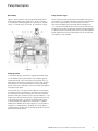
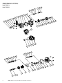
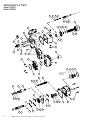
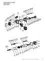
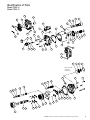
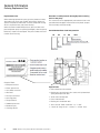
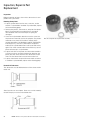
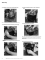
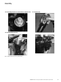
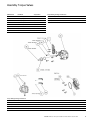
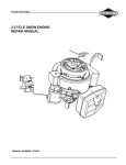
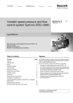
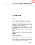
PVM Piston Pumps
Service Manual
PVM018/020
PVM045/050
PVM057/063
PVM074/081
PVM098/106
PVM131/141
Table of Contents
Service Parts
Pump Description ........................................................................................................................................................................... 3
Basic pump
Pump Operation
Controls Types
Part Identification............................................................................................................................................................................. 4
PVM 018/020..................................................................................................................................................................... 9
PVM 045/050................................................................................................................................................................... 14
PVM 057/063................................................................................................................................................................... 15
PVM 074/081................................................................................................................................................................... 19
PVM 098/106................................................................................................................................................................... 24
PVM 131/141................................................................................................................................................................... 29
Repair
General Information....................................................................................................................................................................... 34
Replacement Parts
Required Tools
Special Tools
Disassembly, Inspection and Assembly........................................................................................................................................ 35
Disassembly.................................................................................................................................................................... 36
Inspection Repair and Replacement................................................................................................................................ 40
Assembly......................................................................................................................................................................... 42
Testing ......................................................................................................................................................................................... 46
Troubleshooting ............................................................................................................................................................................ 46
Assembly Torque Values............................................................................................................................................................... 47
2
EATON PVM Piston Pump Service Manual E-PUIO-II001-E3 October 2013
Pump Description
Basic Pump
Pump Controls Types
Figure 1 shows the basic construction of the PVM series
piston pump. Major parts include the 1. Shaft 2. Housing,
3. Swash plate,4. Rotating group, 5. Valve plate, 6. Control
sleeve, 7. Control rod, 8. End Cover, 9. Control 10. Flange
Three common pump control types are available. One type is
the standard “A” compensator control that limits pump outlet
pressure to a desired level. The other type is the “B+C”
pressure limited/load sensing control. Now available is the
“IC” (Industrial Control) which can be used as a load sensing
compensator, remote compensator control and electrohydraulic control. These limit pump outlet pressure and also regulate
pump displacement to match load requirements. A cold start
valve option is also available.
Figure 1
Pump Operation
In axial piston pumps, the pistons reciprocate parallel to the
axis of rotation of the cylinder barrel. The simplest type of
axial piston pump is the swash plate in-line design. The cylinder barrel in this pump is turned by the drive shaft. Pistons
fitted to bores in the cylinder barrel are connected through
piston shoes and a shoe plate, so that the shoes bear against
an angled swash plate.
As the barrel turns, the piston shoes follow the swash plate,
causing the pistons to reciprocate. The ports are arranged in
the valve plate so that the pistons pass the inlet as they are
pulled out and pass the outlet as they are forced back in. The
displacement of axial piston pumps is determined by the size
and number of pistons, as well as the stroke length which
is determined by the angle of the swash plate. In variable
displacement Models of the in-line pump, the swash plate is
installed in a saddle Bearing. “Pivoting” the swash plate in
saddle bearings changes the swash plate angle to increase or
decrease the piston stroke.
EATON PVM Piston Pump Service Manual E-PUIO-II001-E3 October 2013
3
Identification of Parts
Model PVM018
Model PVM020
36
33
32
35
2
25
27
4
3
1
23
29
24
21
37
38
34
41
40
39
22
30
10
9
58
61
60
59
57
63
62
23
73
52
47
46
45
44
43
53
54
74
55
23
72
26
56
48
42
49
51
50
8
7
15
16
14
29
11
27
64
65
31
4
6
4
5
6
EATON PVM
PVMPiston
PistonPumps
Pump Service
Parts Manual
ManualV-PP-TP-0001-E
E-PUIO-II001-E3
July
October
2011 2013
EATON PVM Piston Pump Service Manual
66
Parts List
Model
PVM018
Model PVM018
Model
PVM020
Model PVM020
Item
Part No.
Qty.
1
2
3
4
5
6
7
8
9
10
11
12
13
14
15
16
17
18
19
20
21
See Table 1
114953-030
104166-011
104166-017
See Table 2
See Table 2
Not Used
417381
See Table 3
16028-303
See Table 4
Not Used
Not Used
943990
937340
101680-162
Not Used
Not Used
Not Used
Not Used
See Table 5
1
4
2
1
1
1
22
Note
Description
Item
Part No.
Qty.
Note
Description
46
104166-022
1
B
O-Ring
47
16028-303
1
48
932921
1
49
943992
1
50
02-340318
2
51
Not Used
52
16026-608
1
D
Pin
53
409998
1
D
Button
54
409999
1
D
Spring Seat
55
Not Used
56
943905
1
57
937061
1
C
Cylinder Barrel (018)
57
937062
1
CK
Cylinder Barrel (020)
58
101680-145
1
CL
Retaining Ring
59
937338
1
C
Spring Guide, Outer
60
937336
1
C
Spring
61
937337
1
C
Spring Guide, Inner
1
Pressure Compensator
Soc HD Cap Screw M5
O-Ring
O-Ring
Drive Shaft
Key
Retaining Ring
Bearing S/A
Valve Plate
Pin (Valve Plate)
Mounting Flange
Soc HD Cap Screw M5
Soc HD Cap Screw M5
Flange Gasket
Shaft Seal
Retaining Ring
Seal Collar
Retaining Ring
O-Ring
Filter
Housing
62
913833
1
C
Pin Retainer
See Table 5
2
O-Ring Plug S/A
63
937339
3
C
Pin
23
See Tables 6&7
1
End Cover
64
02-334516
9
CK
Piston Shoe S/A (018)
24
937317
1
Gasket
64
02-335670
9
CL
Piston Shoe S/A (020)
25
115046-002
1
O-Ring Plug S/A
65
937069
1
C
Shoe Retainer
26
115046-004
2
O-Ring Plug S/A
66
937070
1
C
Ballguide
27
114976-040
8
Soc HD Cap Screw
67
Not Used
Spacer
28
Not Used
Soc HD Cap Screw
68
Not Used
Screw
29
16026-608
4
Roll Pin
69
Not Used
Adapter
30
02-335336
1
E
Bearing S/A
70
Not Used
Screw
31
4992182-xxx
A/R
J
Spacer
71
Not Used
32
943933
1
Control Cap
72
104166-152
1
33
115016-221
1
O-Ring
73
See Table 8
1
Coupling
34
997089
1
Adjustment Screw
74
See Table 8
1
Retaining Ring
35
4992732-001
1
Jam Nut
36
8770-015
1
B
Back-Up Ring
37
104166-015
1
B
O-Ring
38
943934
1
39
943931
1
40
937455
1
B
Glide Ring
41
104166-110
1
B
O-Ring
42
943932
1
43
115001-023
1
B
Back-Up Ring
44
104166-023
1
B
O-Ring
45
115001-022
1
B
Back-Up Ring
A Available in control kit. See Table 1.
B Available in seal kit 02-347284.
C Available in rotating group kit 02-347295 for PVM018 or rotating group kit 02-347286 for
PVM020.
D Available in yoke and saddle bearing kit 02-347287.
E Available in shaft bearing kit 02-347288.
F Available in single shaft seal kit 02-347290. Equivalent double shaft seal kit 02-347291.
G Available in control mounting kit 9900104-000.
H Seat bearing cone against shoulder.
J Use spacers to shim as required to obtain 0,01 to 0,10 mm (0.00039 to 0.0039 in.) axial shaft
end play.
K For PVM018 only.
L For PVM020 only.
M Warning: Use Vickers authorized chain link only. Cotter pins on industry standard chain link
will fail.
AG
ABG
ABG
1
1
1
1
EH
1
1
1
B
BF
BF
B
B
Adjustment Sleeve
Control Piston
Sleeve
EATON PVM Piston Pump Service Manual
Pin
M
Chain Link
Swashplate
D
Cradle Bearing S/A
Screw Socket Flat Head
Inner Bias Spring
Outer Bias Spring
O-Ring, Adapter
B
O-Ring, End Cover
EATON
EATON
PVM PVM
Piston
Piston
PumpPumps
Service
Parts
Manual
Manual
E-PUIO-II001-E3
V-PP-TP-0001-E
October
July 2011
2013
5
5
7
Parts
Parts Tables
Tables 11-8
-8
Model PVM018
Model PVM020
Table 1 – Pressure Compensator
Table 2 – Shaft and Key and Retaining Ring
Model Code Position
SAE Port
Metric Port
BSPP Port
1
13, 14
17, 18, 19, 20, 21
All
All
01/02
01/02
01/02
01/02
01/02
01/02
01/02
01/02
03/04
03/04
03/04
03/04
03/04
03/04
03/04
03/04
05
05
05
05
A2800
A0700
B2811
C2811
B2824
C2824
B0711
C0711
B0724
C0724
B2811
C2811
B2824
C2824
B0711
C0711
B0724
C0724
B2811
C2811
B2824
C2824
114969-001
114969-002
114970-001
114970-002
114970-003
114970-004
114970-005
114970-006
114970-007
114970-008
114970-009
114970-010
114970-011
114970-012
114970-013
114970-014
114970-015
114970-016
114970-017
114970-018
114970-019
114970-020
05
B0711
114970-021
05
C0711
114970-022
05
B0724
114970-023
05
C0724
114970-024
Table 3 – Industrial Valve Plate
Model Code Position
9
Model Code Position
5
6
9, 10
11
25
05
C
O
937445
4992730-001
06
C
O
937446
4992730-002
07
C
O
937447
–
08
C
O
937448
–
15
B
O
937456
4992728-001
17
D
O
937088
4992728-002
01
A
O
937183
4992730-006
02
A
O
937184
4992730-007
03
B/C
O
937185
–
04
A/B/C
O
937186
–
05
C
A
937449
4992730-001
06
C
A
937450
4992730-003
07
C
A
937451
4992728-002
08
C
A
937452
–
20
C
O
943941
–
16
B
O
996833
4992728-003
17
D
O
996834
–
Table 4 – Mounting Flange
Model Code Position
11
11
13, 14
15, 16
A
01/02
00/AA/AC
937441
943994
A
01/02
AB/AD
943994
937441
A
03/04
00/AA/AC
997020
A
03/04
AB/AD
997021
A
05
00/AA/AC
996928
4, 5, 6
7, 8
A
05
AB/AD
996930
018
ER
937158
B
03/04
00/AA/AC
937442
018
MR
937159
B
03/04
AB/AD
937443
018
EL
937160
B
05
00/AA/AC
996929
018
ML
937161
B
05
AB/AD
996931
020
ER
937412
C
01/02
00/AA/AC
937429
020
MR
937411
C
01/02
AB/AD
944105
020
EL
937412
C
03/04
00/AA/AC
944105
997022
020
ML
937414
C
03/04
AB/AD
997023
937429
C
05
00/AA/AC
996932
C
05
AB/AD
996934
D
01/02
00/AA/AC
937430
D
01/02
AB/AD
937431
D
03/04
00/AA/AC
–
D
03/04
AB/AD
–
D
05
00/AA/AC
996933
D
05
AB/AD
996935
6
8
6 EATON
PVM Piston Pump Service Manual E-PUIO-II001-E3 October 2013
EATON PVM Piston Pumps Parts Manual V-PP-TP-0001-E July 2011
EATON PVM Piston Pump Service Manual
Parts Tables 1-8
Model PVM018
Model PVM020
Table 5 – Housing and Port Plugs
Table 6 – End Cover (Non Thru Drive)
Model Code Position
21
13, 14
Model Code Position
22
8
12, 13, 14
23
02
943989
115046-008
R
S01
937150
01
943989
115046-008
R
S02
937435
04
937164
115050-018
L
S01
937421
03
937164
115050-018
L
S02
937438
05
937165
4992947-001
R
S03
937151
R
S04
937436
L
S03
937437
L
S04
937439
R
E01
937304
R
E02
937306
L
E01
944173
Table 7 – End Cover (Thru Drive)
Model Code Position
23
8
13, 14
25
R
01
A/B
937460
L
E02
937192
R
02
A/B
937187
R
E03
937305
R
03
A/B
937461
R
E04
937307
R
04
A/B
937188
L
E03
937191
R
05
A/B
937462
L
E04
937194
R
03
G/H
937463
R
S05
937052
R
04
G/H
937189
R
E05
937308
R
05
G/H
937464
L
S05
937940
L
01
A/B
996816
L
E05
944170
L
02
A/B
996819
L
03
A/B
996817
L
04
A/B
996820
L
05
A/B
996822
L
03
G/H
996818
Model Code Position
L
04
G/H
996821
25
Ref
L
05
G/H
996823
A
A9
937454
101680-062
B
A11
937453
101680-062
C
B13
–
–
D
B15
–
–
G
MA9
937454
101680-062
Torque Values
H
MA11
937453
101680-062
2
7,4-9 Nm (65-80 in-lb)
J
MB13
–
–
22
95-108 Nm (70-80 ft-lb)
25
3.4-4.5 Nm (30.1-39.8 lbf-in)
26
23-25,8 Nm (17-19 ft-lb)
27
63-77 Nm (46-57 ft-lb)
32
210-230 Nm (155-170 ft-lb)
35
18-24 Nm (13-18 ft-lb)
Torque Values
Item
EATON PVM Piston Pump Service Manual
Table 8 – Coupling (Thru Drive) and Retaining Ring
73
74
EATON
EATON
PVM PVM
Piston
Piston
PumpPumps
Service
Parts
Manual
Manual
E-PUIO-II001-E3
V-PP-TP-0001-E
October
July 2011
2013
7
7
9
Identification
Identification of
of Model
Model Code
Code
Model
ModelPVM018
PVM018
Model
ModelPVM020
PVM020
PVM
018
E
R
01
A
S
01
AA
A
28
00
00
0
0
A
0
A
1, 2, 3
4, 5, 6
7
8
9, 10
11
12
13, 14
15, 16
17
18, 19
20, 21
22, 23
24
25
26
27
28
1, 2, 3 Pump Series
12 Main Port Location
20, 21
PVM M-Series variable piston
pump
S Side
E End (na on thru drive)
00 None
4, 5, 6 Displacement
018 18.0 cm3/rev (1.10 in3/rev)
280 bar
020 21.1 cm3/rev (1.24 in3/rev)
230 bar
7 Valve Plate
E - Industrial (1800 rpm max)
M - Mobile equipment
speeds
8 Input Rotation
R - Clockwise (righthand)
L - Counterclockwise
(lefthand)
9, 10 Input Shaft
01 SAE J744-16-1 A straight
key
02 SAE J744-19-1 19mm
straight key
03 SAE J744-16-4 A 9T spline
04 SAE J744-16-4 A 11T
spline
05 SAE J744-22-1 B straight
key
06 SAE J744-25-1 B-B
straight key
07 SAE J744-22-4 B 13T
spline
08 SAE J744-25-4 B-B 15T
spline
11 Mounting Flange
A SAE J744-82-2 (SAE A 2
bolt)
C SAE J744-101-2 (SAE B 2
bolt)
10
8
8
13, 14 Main Port Type
01 SAE J514 tube ports
02 SAE J518 flange ports
03 ISO 6149-1 tube ports
04 ISO 6162 flange ports
15, 16 Pump Special
Features
Flow Comp
Setting
11 10-11 bar (145-174 psi)
20 19-21 bar (275.5-304.5
psi)
24 23-25 bar (333.5-362.5
psi)
Torque Limiter
Setting
22, 23
00 None (single shaft seal)
00 None
AA Adjustable maximum
displacement stop and single
shaft seal (standard)
24 Compensator Special
Features
AB Double shaft seal, two
way
AD Adjustable maximum
displacement stop and
double shaft seal
17 Control
0 None
25 Auxiliary Mounting Pad
0 None
A SAE A 2 bolt 9T spline
B SAE A 2 bolt 11T spline
0 None
26 Paint
A Pressure compensator
0 No paint
B Pressure and flow
compensator with bleed
orifice
A Blue (standard)
C Pressure and flow
compensator with plugged
orifice
0 None
18, 19
Pressure Comp
Setting
27 Customer Identification
28 Design Code
A A (initial release)
00 None
07 66-74 bar (957-1073 psi)
23 227-234 bar (3277-3393
psi) 020 cm3/rev
28 276-284 bar (4002-4118
psi) 018 cm3/rev
EATON PVM Piston Pumps Parts Manual V-PP-TP-0001-E July 2011
EATON PVM Piston Pump Service Manual E-PUIO-II001-E3 October 2013
EATON PVM Piston Pump Service Manual
Identification
Identification of Parts
Model
PVM045
Model PVM045
Model
PVM050
Model PVM050
37
36
33
32
35
27
1
2
4
3
23
29
24
21
41
38
34
39
40
22
30
10
9
58
59
60
61
57
62
66
63
23
73
74
70
52
69
71
53
72
54
26
23
56
55
48
47
45
46
44
42
43
51
50
8
7
15
16
14
29
11
27
49
64
65
31
18
5
6
EATON PVM Piston Pump Service Manual
EATON PVM Piston Pump Service Manual E-PUIO-II001-E3 October 2013
EATON PVM Piston Pumps Parts Manual V-PP-TP-0001-E July 2011
9
9
Parts List
Model
PVM045
Model PVM045
Model PVM050
Model PVM050
Item
Part No.
Qty.
1
See Table 1
1
2
114953-030
4
3
104166-011
2
4
104166-017
1
5
See Table 2
6
7
Note
Description
Item
Part No.
Qty.
Note
Description
Pressure Compensator
46
104166-027
1
B
O-Ring
AG
Soc HD Cap Screw M5
47
95902-050
1
ABG
O-Ring
48
932921
1
ABG
O-Ring
49
932918
1
1
Drive Shaft
50
937055
2
D
Cradle Bearing
See Table 2
1
Key
51
114995-010
2
D
Screw Socket Flat Head
See Table 2
1
Retaining Ring
52
16026-608
1
D
Pin
8
419627
1
Bearing S/A
53
409998
1
D
Button
9
See Table 3
1
Valve Plate
54
934189
1
D
Spring Seat
10
114997-004
1
Pin (Valve Plate)
55
932928
1
11
See Table 4
1
Mounting Flange
56
932929
1
12
Not Used
Soc HD Cap Screw M5
57
933028
1
CK
Cylinder Barrel (045)
13
Not Used
Soc HD Cap Screw M5
57
932930
1
CL
Cylinder Barrel (050)
14
932915
1
B
Flange Gasket
58
101680-162
1
C
Retaining Ring
15
626933
1
BF
Shaft Seal
59
423368
1
C
Spring Guide, Outer
16
101680-175
1
BF
Retaining Ring
60
402579
1
C
Spring
17
Not Used
Seal Collar
61
404932
1
C
Spring Guide, Inner
18
Not Used
Retaining Ring
62
410050
1
C
Pin Retainer
19
Not Used
O-Ring
63
114996-006
3
C
Pin
20
Not Used
Filter
64
415621
9
CK
Piston Shoe S/A (045)
21
See Table 5
1
Housing
64
02-328123
9
CL
Piston Shoe S/A (050)
22
See Table 5
2
O-Ring Plug S/A
65
402650
1
C
Shoe Retainer
23
See Tables 6&7
1
End Cover
66
402580
1
C
Ballguide
24
932916
1
Gasket
67
Not Used
Spacer
25
Not Used
O-Ring Plug S/A
68
Not Used
Screw
26
See Tables 6&7
2
O-Ring Plug S/A
69
See Table 7
1
27
114977-035
8
Soc HD Cap Screw
70
114976-025
3
28
Not Used
Soc HD Cap Screw
71
104166-155
1
B
O-Ring, Adapter
29
96201-062
4
Roll Pin
72
104166-152
1
B
O-Ring, End Cover
30
473914
1
E
Bearing S/A
73
See Table 8
1
Coupling
31
4992184-xxx
A/R
J
Spacer
74
See Table 8
1
Retaining Ring
32
934286
1
Control Cap
33
115016-224
1
34
934287
1
A
B
C
35
4992732-001
1
36
8770-015
1
B
Back-Up Ring
37
104166-015
1
B
O-Ring
38
934340
1
39
932919
1
40
932924
1
B
Glide Ring
41
104166-210
1
B
O-Ring
EH
B
B
O-Ring
Adjustment Screw
Jam Nut
Hex Stop
Control Piston
42
932920
1
Sleeve
43
114998-028
1
B
Back-Up Ring
44
104166-028
1
B
O-Ring
45
114998-027
1
B
Back-Up Ring
10
10
Pin
M
Chain Link
Swashplate
Inner Bias Spring
Outer Bias Spring
Adapter
Screw
Available in control kit. See Table 1.
Available in seal kit 02-346161.
Available in rotating group kit 02-346162 for PVM045 or rotating group kit 02-346172 for
PVM050.
D Available in yoke and saddle bearing kit 02-346163.
E Available in shaft bearing kit 02-346164.
F Available in single shaft seal kit 02-346166. Equivalent double shaft seal kit 02-346167.
G Available in control mounting kit 9900104-000.
H Seat bearing cone against shoulder.
J Use spacers to shim as required to obtain 0,01 to 0,10 mm (0.00039 to 0.0039 in.) axial
shaft end play.
K For PVM045 only.
L For PVM050 only.
M Warning: Use Vickers authorized chain link only. Cotter pins on industry standard chain link
will fail.
EATON PVM Piston Pump Service Manual
EATON PVM Piston Pump Service Manual E-PUIO-II001-E3 October 2013
EATON PVM Piston Pumps Parts Manual V-PP-TP-0001-E July 2011
19
Parts Tables
Parts
Tables 11 -- 88
Model PVM045
Model PVM050
Table 1 – Pressure Compensator
Model Code Position
SAE Port
Metric Port
BSPP Port
13, 14
17, 18, 19, 20, 21
All
All
01/02
01/02
01/02
01/02
01/02
01/02
01/02
01/02
03/04
03/04
03/04
03/04
03/04
03/04
03/04
03/04
05
05
05
05
A2800
A0700
B2811
C2811
B2824
C2824
B0711
C0711
B0724
C0724
B2811
C2811
B2824
C2824
B0711
C0711
B0724
C0724
B2811
C2811
B2824
C2824
05
Table 2 – Shaft, Key and Retaining Ring
1
Model Code Position
5
6
11
26
02-345631
02-345629
02-345594
02-345596
02-345598
02-345600
02-345601
02-345602
02-345603
02-345604
02-345606
02-345608
02-345610
02-345612
02-345613
02-345614
02-345615
02-345616
02-345618
02-345620
02-345622
02-345624
05
C
O
934380
22971
–
06
C
O
934381
58303
96098-100
07
C
O
934382
–
–
08
C
O
932927
–
–
05
C
A/B/G/H
934391
22971
–
06
C
A/B/G/H
934392
58303
96098-100
07
C
A/B/G/H
934393
–
–
08
C
A/B/G/H
934394
–
–
B0711
05
Table 3 – Industrial Valve Plate
Model Code Position
9
4, 5, 6
7, 8
045
ER
932922
045
MR
932925
045
EL
934275
045
ML
934276
050
ER
934280
02-345625
050
MR
933027
C0711
02-345626
050
EL
934278
05
B0724
02-345627
050
ML
934277
05
C0724
02-345628
Table 4 – Mounting Flange
Table 5 – Housing and Drain Plugs S/A
Model Code Position
11
Model Code Position
13, 14
21
22
11
13, 14
15, 16
C
01/02
00/AA/AC
932914
02
932912
–
C
01/02
AB/AD
934397
01
932912
–
C
03/04
00/AA/AC
943776
04
934273
–
C
03/04
AB/AD
943775
03
934273
–
C
05
00/AA/AC
934399
05
934401
49929447-001
C
05
AB/AD
934400
D
01/02
00/AA/AC
943821
D
01/02
AB/AD
943822
D
03/04
00/AA/AC
943274
D
03/04
AB/AD
934398
D
05
00/AA/AC
943773
D
05
AB/AD
943774
20
7
9, 10
EATON PVM Piston Pump Service ManualEATON
EATON PVM Piston Pumps Parts Manual V-PP-TP-0001-E July 2011
PVM Piston Pump Service Manual E-PUIO-II001-E3 October 2013
11
11
Parts Tables 1 - 8
Model PVM045
Model PVM050
Table 6 – End Cover (Non Thru Drive) and Gauge Port Plug
Table 7 – End Cover (Thru Drive), Gauge Port Plug and Adapter
Model Code Position
Model Code Position
23
8
12, 13, 14
R
S01
934254
R
S02
932909
L
S01
L
R
26
23
26
69
8
13, 14
25
115046-006
R
01
A/B
934301
115046-006
–
115046-006
R
02
A/B
934238
115046-006
–
934257
115046-006
R
03
A/B
934359
115050-022
–
S02
934261
115046-006
R
04
A/B
934269
115050-022
–
S03
934255
115050-022
R
05
A/B
934363
4992947-002
–
R
S04
934259
115050-022
R
03
G/H
934365
115050-022
–
L
S03
934258
115050-022
R
04
G/H
934364
115050-022
–
L
S04
934262
115050-022
R
05
G/H
934366
4992947-002
–
R
E01
934355
115046-006
R
01
C/D
934301
115046-006
934294
R
E02
934264
115046-006
R
02
C/D
934238
115046-006
934294
L
E01
934367
115046-006
R
03
C/D
934359
115050-022
934294
L
E02
934267
115046-006
R
04
C/D
934269
115050-022
934294
R
E03
934357
115050-022
R
05
C/D
934363
4992947-002
934294
R
E04
934263
115050-022
R
03
J/K
934365
115050-022
934402
L
E03
934369
115050-022
R
04
J/K
934364
115050-022
934402
L
E04
934268
115050-022
R
05
J/K
934366
4992947-002
934402
R
S05
934360
4992947-002
L
01
A/B
934370
115046-006
–
R
E05
934361
4992947-002
L
02
A/B
934271
115046-006
–
L
S05
934373
4992947-002
L
03
A/B
934372
115050-022
–
L
E05
934374
4992947-002
L
04
A/B
934272
115050-022
–
L
05
A/B
934375
4992947-002
–
L
03
G/H
934377
115050-022
–
L
04
G/H
934376
115050-022
–
L
05
G/H
934378
4992947-002
–
L
01
C/D
934370
115046-006
934294
L
02
C/D
934271
115046-006
934294
L
03
C/D
934372
115050-022
934294
L
04
C/D
934272
115050-022
934294
L
05
C/D
934375
4992947-002
934294
L
03
J/K
934377
115050-022
934402
L
04
J/K
934376
115050-022
934402
L
05
J/K
934378
4992947-002
934402
Table 8 – Coupling (Thru Drive) and Retaining Ring
Model Code Position
73
74
25
Ref
A
A9
937238
–
B
A11
937236
–
C
B13
937237
115015-078
D
B15
943792
115015-078
G
MA9
937238
–
H
MA11
937236
–
J
MB13
937237
115015-078
K
MB15
943792
115015-078
Torque Values
12
12
Item
Torque Values
2
7,4-9 Nm (65-80 in-lb)
22
95-108 Nm (70-80 ft-lb)
26
23-25,8 Nm (17-19 ft-lb)
27
63-77 Nm (46-57 ft-lb)
32
210-230 Nm (155-170 ft-lb)
35
18-24 Nm (13-18 ft-lb)
51
3,6-4,4 Nm (32-39 in-lb)
70
42-50 Nm (31-36,8 ft-lb)
EATON PVM Piston Pump Service Manual
EATON PVM Piston Pump Service Manual E-PUIO-II001-E3 October 2013
EATON PVM Piston Pumps Parts Manual V-PP-TP-0001-E July 2011
21
Identification of
Identification
of Model
Model Code
Code
Model PVM045
Model
PVM045
Model PVM050
Model
PVM050
PVM
045
E
R
06
C
S
01
AA
A
28
00
00
0
0
A
0
A
1, 2, 3
4, 5, 6
7
8
9, 10
11
12
13, 14
15, 16
17
18, 19
20, 21
22, 23
24
25
26
27
28
1, 2, 3 Pump Series
PVM M-Series variable piston
pump
4, 5, 6 Displacement
045 45.1 cm3/rev (2.75 in3/
rev) 280 bar
050 50.0 cm /rev (3.00 in /
rev) 230 bar
3
3
7 Valve Plate
E - Industrial (1800 rpm max)
M - Mobile equipment
speeds
8 Input Rotation
R - Clockwise (righthand)
L - Counterclockwise
(lefthand)
9, 10 Input Shaft
05 SAE J744-22-1 B straight
key
06 SAE J744-25-1 B-B
straight key
07 SAE J744-22-4 B 13T
spline
08 SAE J744-25-4 B-B 15T
spline
11 Mounting Flange
15, 16 Pump Special
Features
22, 23
Torque Limiter
Setting
00 None (single shaft seal)
00 None
AA Adjustable maximum
displacement stop and single
shaft seal (standard)
24 Compensator Special
Features
AB Double shaft seal, two
way
AD Adjustable maximum
displacement stop and
double shaft seal
17 Control
0 None
A Pressure compensator
B Pressure and flow
compensator with bleed
orifice
C Pressure and flow
compensator with plugged
orifice
18, 19
Pressure Comp
Setting
0 None
25 Auxiliary Mounting Pad
0 None
A SAE A 2 bolt 9T spline
B SAE A 2 bolt 11T spline
C SAE B 2/4 bolt 13T spline
D SAE B 2/4 bolt 15T spline
26 Paint
0 No paint
A Blue (standard)
27 Customer Identification
0 None
28 Design Code
A A (initial release)
00 None
07 66-74 bar (957-1073 psi)
23 227-234 bar (3277-3393
psi) 050 cm3/rev
28 276-284 bar (4002-4118
psi) 045 cm3/rev
C SAE J744-101-2 (SAE B 2
bolt)
12 Main Port Location
S Side
E End (na on thru drive)
13, 14 Main Port Type
01 SAE J514 tube ports
02 SAE J518 flange ports
03 ISO 6149-1 tube ports
04 ISO 6162 flange ports
22
20, 21
Flow Comp
Setting
00 None
11 10-11 bar (145-174 psi)
20 19-21 bar (275.5-304.5
psi)
24 23-25 bar (333.5-362.5
psi)
EATON PVM Piston Pump Service Manual
EATON PVM Piston Pumps Parts Manual V-PP-TP-0001-E July 2011
EATON PVM Piston Pump Service Manual E-PUIO-II001-E3 October 2013
13
13
Identification of Parts
Model
PVM057
Identification
of Parts
Model PVM063
Model PVM057
Model PVM063
36
37
38
34
41
9
22
1
31
58
40
39
57
59
24
2
25
60
61
3
28
30
33
32
10
21
29
22
47
73
35
26
27
70
23
69
23
19
71
42
44
53
15
18
Parts for double
shaft seal
models only
72
55
52
17
56
54
48
64
45
46
43
11
8
51
67
5
14
6
68
65
16
14
29
50
49
66
EATON PVM Piston Pump Service Manual E-PUIO-II001-E3 October 2013
14
15
12
EATON PVM Piston Pump Service Manual
Parts List
Model
PVM057
Model PVM057
Model
PVM063
Model PVM063
Item
Part No.
Qty.
Note
Description
Item
Part No.
Qty.
Note
Description
1
See Table 1
1
2
114975-035
4
AG
Pressure Compensator
46
104166-126
1
B
O-Ring
Soc HD Cap Screw M5
47
16028-303
1
3
4992737-111
3
ABG
4
Not Used
O-Ring
48
934493
1
O-Ring
49
934086
1
5
See Table 2
1
Drive Shaft
50
943984
2
D
6
See Table 2
Cradle Bearing
1
Key
51
114995-010
2
D
Screw Socket Flat Head
7
Not Used
8
02-334757
1
Retaining Ring
52
95749-038
1
D
Pin
Bearing S/A
53
409998
1
D
9
See Table 3
Button
1
Valve Plate
54
934429
1
D
10
Spring Seat
95904-068
1
Pin (Valve Plate)
55
937489
1
11
See Table 4
1
Mounting Flange
56
937488
1
12
114977-040
4
Soc HD Cap Screw M5
57
934405
1
CK
Cylinder Barrel (057)
13
Not Used
Soc HD Cap Screw M5
57
934553
1
CL
Cylinder Barrel (063)
14
934445
1
B
Flange Gasket
58
101680-175
1
C
Retaining Ring
15
513439
1
BF
Shaft Seal
59
584524
1
C
Spring Guide, Outer
16
101680-200
1
BF
Retaining Ring
60
627524
1
C
Spring
17
934058
Seal Collar
61
680624
1
C
Spring Guide, Inner
18
101680-300
Retaining Ring
62
Not Used
19
104166-040
O-Ring
63
Not Used
20
Not Used
Filter
64
02-306362
9
CK
Piston Shoe S/A (057)
21
See Table 5
1
Housing
64
02-306363
9
CL
Piston Shoe S/A (063)
22
See Table 5
2
O-Ring Plug S/A
65
584512
1
CK
Shoe Retainer (057)
23
See Tables 6&7
1
End Cover
65
860754
1
CL
Shoe Retainer (063)
24
934444
1
Gasket
66
690218
2
C
Hold Down Straps
25
16103-104
2
O-Ring Plug S/A
67
690801
2
C
Spacer
26
115046-006
2
O-Ring Plug S/A
68
114974-025
4
C
Screw
27
114977-045
3
Soc HD Cap Screw
69
See Table 7
1
28
114977-090
1
Soc HD Cap Screw
70
114977-025
3
29
96201-062
4
Roll Pin
71
See Table 7
1
B
O-Ring, Adapter
30
02-328741
1
E
Bearing S/A
72
See Table 7
1
B
O-Ring, End Cover
31
4992188-xxx
A/R
J
Spacer
73
See Table 8
1
32
943930
1
Control Cap
74
Not Used
33
934580
1
O-Ring
34
943985
1
35
4992732-002
1
A
B
C
36
8770-015
1
B
Back-Up Ring
37
104166-015
1
B
O-Ring
38
937407
1
39
934052
1
40
934489
1
B
41
104166-211
1
B
42
934053
1
43
115000-127
1
B
Back-Up Ring
44
104166-127
1
B
O-Ring
45
115000-126
1
B
Back-Up Ring
EH
B
B
Adjustment Screw
Jam Nut
Hex Stop
Control Piston
Glide Ring
O-Ring
Sleeve
EATON PVM Piston Pump Service Manual
Pin
M
Chain Link
Swashplate
Inner Bias Spring
Outer Bias Spring
Pin Retainer
Pin
Adapter
Screw
Coupling
Retaining Ring
Available in control kit. See Table 1.
Available in seal kit 02-346217.
Available in rotating group kit 02-346216 for PVM057 or rotating group kit 02-346224 for
PVM063.
D Available in yoke and saddle bearing kit 02-346219.
E Available in shaft bearing kit 02-346220.
F Available in single shaft seal kit 02-346222. Equivalent double shaft seal kit 02-346223.
G Available in control mounting kit 9900105-000.
H Seat bearing cone against shoulder.
J Use spacers to shim as required to obtain 0,01 to 0,10 mm (0.00039 to 0.0039 in.) axial
shaft end play.
K For PVM057 only.
L For PVM063 only.
M Warning: Use Vickers authorized chain link only. Cotter pins on industry standard chain link
will fail.
15
EATON
EATON
PVM PVM
Piston
Piston
PumpPumps
Service
Parts
Manual
Manual
E-PUIO-II001-E3
V-PP-TP-0001-E
October
July 2011
2013
15
25
Parts Tables
1 -- 88
Parts
Tables
1
Model PVM057
Model PVM063
Table 1 – Pressure Compensator
Table 2 – Shaft and Key
Model Code Position
13, 14
17, 18, 19
20, 21
All
A28
00
All
A07
00
01/02
B28
01/02
01/02
1
Model Code Position
5
6
9, 10
11
25
02-125160
06
C
O
937011
4992727-003
02-125162
07
C
O
934574
–
11
02-346306
08
C
O
937009
–
B28
24
02-160591
09
E/G
O
937008
114516
C07
24
02-306056
11
E/G
O
934338
–
01/02
C28
11
02-346305
17
E/G
O
937044
4992727-003
01/02
C28
24
02-125161
18
E/G
O
937050
4992727-001
03/04
B07
11
02-347729
06
C
A to M
937382
–
03/04
B08
24
02-347728
07
C
A to M
937383
–
03/04
B28
11
02-347730
08
C
A to M
937384
–
03/04
B28
24
02-347727
09
E/G
A to M
937380
–
03/04
C28
11
02-346307
11
E/G
A to M
937051
–
03/04
C28
24
02-346308
17
E/H
A to M
939386
–
18
E/H
A to M
937385
–
Table 3 – Industrial Valve Plate
Model Code Position
Table 4 – Mounting Flange
9
4, 5, 6
7, 8
057
ER
943806
057
MR
943970
057
EL
943971
057
ML
943972
063
ER
943973
063
MR
943974
063
EL
943975
063
ML
943976
Model Code Position
Table 5 – Housing
Model Code Position
13, 14
21
22
01
934090
115046-010
02
934090
115046-010
03
934599
115050-022
04
934599
115050-022
16
26
16EATON
11
11
13, 14
15, 16
C
01/02
00/AA/AC
934159
C
01/02
AB/AD
937286
C
03/04
00/AA/AC
937323
C
03/04
AB/AD
937324
D
03/04
00/AA/AC
937287
D
03/04
AB/AD
937288
E
01/02
00/AA/AC
937278
E
01/02
AB/AD
937289
E
03/04
00/AA/AC
937325
E
03/04
AB/AD
937326
F
03/04
00/AA/AC
937290
F
03/04
AB/AD
937291
G
01/02
00/AA/AC
934087
G
01/02
AB/AD
934417
G
03/04
00/AA/AC
937327
G
03/04
AB/AD
937328
H
03/04
00/AA/AC
937001
H
03/04
AB/AD
937002
PVM Piston Pump Service Manual E-PUIO-II001-E3 October 2013
EATON PVM Piston Pumps Parts Manual V-PP-TP-0001-E July 2011
EATON PVM Piston Pump Service Manual
Parts Tables 1 - 8
Model PVM057
Model PVM063
Table 6 – End Cover (Non Thru Drive)
Model Code Position
8
12, 13, 14
R
S02
R
S04
L
Table 7 – End Cover (Thru Drive), Adapter and O-Rings
23
Model Code Position
23
69
71
72
8
12, 13, 14
25
934088
R
02
A/B
934251
–
–
576601
937208
R
02
C/D
934251
934296
401525
576601
S02
937209
R
02
E/F
934251
934298
353264
576601
L
S04
937210
R
04
A/B
937257
–
–
576601
R
E01
937375
R
04
C/D
937257
934567
401525
576601
R
E02
937211
R
04
E/F
937257
934569
353264
576601
R
E03
937376
R
04
G/H
937378
–
–
943809
R
E04
937248
R
04
J/K
937257
934568
401525
943809
L
E01
937377
R
04
L/M
937257
934570
353264
943809
L
E02
934236
L
02
A/B
937258
–
–
576601
L
E03
937144
L
02
C/D
937258
934296
401525
576601
L
E04
937213
L
02
E/F
937258
934298
353264
576601
L
04
A/B
937259
–
–
576601
L
04
C/D
937259
934567
401525
576601
L
04
E/F
937259
934569
353264
576601
L
04
G/H
937379
–
–
943809
L
04
J/K
937259
934568
401525
943809
L
04
L/M
937259
934570
353264
943809
Table 8 – Coupling
Model Code Position
73
25
Ref
A
A9
526682
B
A11
998637
C
B13
526694
D
B15
526695
E
C14
526696
G
MA11
998637
J
MB15
L
MC14
Torque Values
Item
Torque Values
526695
2
31-37 Nm (23-27.4 ft-lb)
526696
12
103-127 Nm (76.2-94 ft-lb)
22
75-83 Nm (55.5-61.4 ft-lb)
25
15-16 Nm (11.1-11.8 ft-lb)
26
29-32 Nm (21.5-23.7 ft-lb)
27
103-127 Nm (76.2-94 ft-lb)
28
103-127 Nm (76.2-94 ft-lb)
32
260-300 Nm (192.4-222 ft-lb)
35
18-24 Nm (13.3-17.8 ft-lb)
51
3,6-4.4 Nm (2.7-3.3 ft-lb)
68
12,9-14,9 Nm (9.6-11 ft-lb)
70
103-127 Nm (76.2-94 ft-lb)
EATON PVM Piston Pump Service Manual
17
EATON
EATON
PVM PVM
Piston
Piston
PumpPumps
Service
Parts
Manual
Manual
E-PUIO-II001-E3
V-PP-TP-0001-E
October
July 2011
2013
17
27
Identification
Identification of
of Model
Model Code
Code
Model
ModelPVM057
PVM057
Model
ModelPVM063
PVM063
PVM
057
E
R
09
E
S
02
AA
A
28
00
00
0
0
A
0
A
1, 2, 3
4, 5, 6
7
8
9, 10
11
12
13, 14
15, 16
17
18, 19
20, 21
22, 23
24
25
26
27
28
1, 2, 3 Pump Series
11 Mounting Flange
PVM M-Series variable piston
pump
C SAE J744-101-2 (SAE B 2
bolt)
4, 5, 6 Displacement
E SAE J744-127-2 (SAE C 2
bolt)
057 57.4 cm3/rev (3.50 in3/
rev) 280 bar
063 63.1 cm3/rev (3.85 in3/
rev) 230 bar
7 Valve Plate
E - Industrial (1800 rpm max)
M - Mobile equipment
speeds
8 Input Rotation
R - Clockwise (righthand)
L - Counterclockwise
(lefthand)
9, 10 Input Shaft
05 SAE J744-22-1 B straight
key
06 SAE J744-25-1 B-B
straight key
07 SAE J744-22-4 B 13T
spline
08 SAE J744-25-4 B-B 15T
spline
09 SAE J744-32-1 C straight
key
10 SAE J744-38-1 C-C
straight key
11 SAE J744-32-4 C 14T
spline
12 SAE J744-38-4 C-C 17T
spline
28
18
18
G SAE J744-127-4 (SAE C 4
bolt)
12 Main Port Location
S Side
E End (na on thru drive)
13, 14 Main Port Type
01 SAE J514 tube ports
02 SAE J518 flange ports
03 ISO 6149-1 tube ports
04 ISO 6162 flange ports
15, 16 Pump Special
Features
Pressure Comp
Setting
18, 19
00 None
07 66-74 bar (957-1073 psi)
23 227-234 bar (3277-3393
psi) 050 cm3/rev
11 10-11 bar (145-174 psi)
20 19-21 bar (275.5-304.5
psi)
24 23-25 bar (333.5-362.5
psi)
Torque Limiter
Setting
22, 23
00 None
24 Compensator Special
Features
AD Adjustable maximum
displacement stop and
double shaft seal
0 None
A Pressure compensator
B Pressure and flow
compensator with bleed
orifice
C Pressure and flow
compensator with plugged
orifice
A A (initial release)
00 None
0 None
0 None
28 Design Code
Flow Comp
Setting
20, 21
AB Double shaft seal, two
way
17 Control
0 None
28 276-284 bar (4002-4118
psi) 045 cm3/rev
00 None (single shaft seal)
AA Adjustable maximum
displacement stop and single
shaft seal (standard)
27 Customer Identification
25 Auxiliary Mounting Pad
A SAE A 2 bolt 9T spline
B SAE A 2 bolt 11T spline
C SAE B 2/4 bolt 13T spline
D SAE B-B 2/4 bolt 15T
spline
E SAE C 2/4 bolt 14T spline
26 Paint
0 No paint
A Blue (standard)
EATON PVM Piston Pumps Parts Manual V-PP-TP-0001-E July 2011
EATON PVM Piston Pump Service Manual E-PUIO-II001-E3 October 2013
EATON PVM Piston Pump Service Manual
Identification of Parts
Identification
Model PVM074 of Parts
Model
PVM074
Model
PVM081
Model PVM081
36
38
34
37
41
40
39
1
2
3
29
25
32
33
24
26
47
35
28
72
23
10
30
22
21
9
31
58
60
59
61
57
26
27
70
73
23
23
45
5
71
69
46
44
42
43
52
48
53
56
55
54
12
6
15
51
50
16
14
29
11
8
49
64
68
30
66
65
67
EATON PVM Piston Pump Service Manual
EATON PVM Piston Pumps Parts Manual V-PP-TP-0001-E July 2011
EATON PVM Piston Pump Service Manual E-PUIO-II001-E3 October 2013
19
19
Parts List
List
Model
PVM074
Model PVM074
Model
PVM081
Model PVM081
Item
Part No.
Qty.
Description
Item
Part No.
Qty.
Note
Description
1
See Table 1
1
2
114975-035
4
AG
Pressure Compensator
46
104166-129
1
B
O-Ring
Soc HD Cap Screw M5
47
95902-050
1
3
4992737-111
3
ABG
4
Not Used
1
O-Ring
48
943252
1
O-Ring
49
943356
1
5
See Table 2
1
Drive Shaft
50
943378
2
D
6
See Table 2
Cradle Bearing
1
Key
51
114995-010
2
D
Screw Socket Flat Head
7
Not Used
8
02-334431
1
Retaining Ring
52
96201-062
1
D
Pin
Bearing S/A
53
933071
1
D
9
See Table 3
Button
1
Valve Plate
54
943411
1
D
10
Spring Seat
95904-068
1
Pin (Valve Plate)
55
Not Used
11
See Table 4
1
Mounting Flange
56
943366
1
12
114977-040
6
Soc HD Cap Screw M5
57
943351
1
CK
Cylinder Barrel (074)
13
Not Used
Soc HD Cap Screw M5
57
943376
1
CL
Cylinder Barrel (081)
14
943362
1
B
Flange Gasket
58
101680-193
1
C
Retaining Ring
15
943427
1
BF
Shaft Seal
59
631568
1
C
Spring Guide, Outer
16
101680-225
1
BF
Retaining Ring
60
584454
1
C
Spring
17
Not Used
Seal Collar
61
584483
1
C
Spring Guide, Inner
18
Not Used
Retaining Ring
62
Not Used
19
Not Used
O-Ring
63
Not Used
20
Not Used
Filter
64
02-305857
9
CK
Piston Shoe S/A (074)
21
See Table 5
1
Housing
64
02-306364
9
CL
Piston Shoe S/A (081)
22
115046-010
2
O-Ring Plug S/A
65
584474
1
C
Shoe Retainer
23
See Tables 6&7
1
End Cover
66
690796
2
C
Hold Down Straps
24
943361
1
Gasket
67
526639
2
C
Spacer
25
115046-002
8
O-Ring Plug S/A
68
114974-025
4
C
Screw
26
115046-006
3
O-Ring Plug S/A
69
See Table 7
1
27
114978-060
4
Soc HD Cap Screw
70
473800
3
28
Not Used
1
Soc HD Cap Screw
71
See Table 7
1
B
O-Ring, Adapter
29
96201-062
4
Roll Pin
72
See Table 7
1
B
O-Ring, End Cover
30
02-334424
1
E
Bearing S/A
73
See Table 8
1
31
4992186-xxx
A/R
J
Spacer
74
Not Used
32
943375
1
Control Cap
33
4992737-138
1
34
943380
1
35
4992732-002
1
36
8770-015
1
B
Back-Up Ring
37
104166-015
1
B
O-Ring
38
943381
1
A
B
C
D
E
F
G
H
J
39
943364
1
40
943367
1
B
Glide Ring
41
104166-118
1
B
O-Ring
42
943363
1
43
115000-131
1
B
Back-Up Ring
44
104166-131
1
B
O-Ring
45
115000-129
1
B
Back-Up Ring
20
20
Note
EH
B
B
O-Ring
Adjustment Screw
Jam Nut
Hex Stop
Control Piston
Sleeve
Pin
M
Chain Link
Swashplate
Inner Bias Spring
Outer Bias Spring
Pin Retainer
Pin
Adapter
Screw
Coupling
Retaining Ring
Available in control kit. See Table 1.
Available in seal kit 9900107-000.
Available in rotating group kit 877421 for PVM074 or rotating group kit 314746 for PVM081.
Available in yoke and saddle bearing kit 9900117-000.
Available in shaft bearing kit 02-334431.
Available in single shaft seal kit 02-334433. Equivalent double shaft seal kit 02-340717.
Available in control mounting kit 9900105-000.
Seat bearing cone against shoulder.
Use to to shim as required to obtain 0,01 to 0,10 mm (0.00039 to 0.0039 in.) axial shaft end
play.
K For PVM074 only.
L For PVM081 only.
M Warning: Use Vickers authorized chain link only. Cotter pins on industry standard chain link
will fail.
EATON PVM Piston Pump Service Manual
EATON PVM Piston Pump Service Manual E-PUIO-II001-E3 October 2013
EATON PVM Piston Pumps Parts Manual V-PP-TP-0001-E July 2011
31
Parts
Tables
1 -- 88
Parts
Tables
1
Model PVM074
Model PVM081
Table 1 – Pressure Compensator
Table 2 – Shaft and Key
Model Code Position
13, 14
17, 18, 19
20, 21
All
A28
00
All
A07
00
02
B28
02
B28
02
1
Model Code Position
5
6
9, 10
25
02-346262
09
O
943428
–
–
10
O
943429
–
11
02-346265
11
O
943368
–
24
02-346266
12
O
943430
–
C07
24
–
18
O
943431
4992727-001
02
C28
11
02-346263
19
O
943432
–
02
C28
24
02-346264
09
A-M
943433
–
04
B07
11
–
10
A-M
943434
–
04
B07
24
–
11
A-M
943435
–
04
B28
11
–
12
A-M
943436
–
04
B28
24
–
18
A-M
943437
4992727-001
04
C28
11
02-346267
19
A-M
943438
–
04
C28
24
02-346268
Table 4 – Mounting Flange
Table 3 – Industrial Valve Plate
Model Code Position
4, 5, 6
7, 8
074
ER
074
MR
9
Model Code Position
11
11
13, 14
15, 16
943365
E
02
00/AA/AC
943396
943439
E
02
AB/AD
943998
04
00/AA/AC
943400
074
EL
943440
E
074
ML
943441
E
04
AB/AD
943404
081
ER
943442
F
04
00/AA/AC
943401
081
MR
943443
F
04
AB/AD
943405
02
00/AA/AC
943352
081
EL
943444
G
081
ML
943445
G
02
AB/AD
943373
G
04
00/AA/AC
943402
G
04
AB/AD
943406
H
04
00/AA/AC
943403
H
04
AB/AD
943407
Table 5 – Housing
Model Code Position
13, 14
21
02
943354
04
943412
32
EATON PVM Piston Pump Service ManualEATON
EATON PVM Piston Pumps Parts Manual V-PP-TP-0001-E July 2011
PVM Piston Pump Service Manual E-PUIO-II001-E3 October 2013
21
21
Parts Tables 1 - 8
Model PVM074
Model PVM081
Table 6 – End Cover (Non Thru Drive)
Model Code Position
8
12, 13, 14
R
S02
R
S04
L
Table 7 – End Cover (Thru Drive), Adapter and O-Rings
23
Model Code Position
23
69
71
72
8
12, 13, 14
25
943358
R
02
A/B
943391
–
–
576601
943416
R
02
C/D
943391
934296
401525
576601
S02
943385
R
02
E/F
943391
934298
353264
576601
L
S04
943423
R
04
A/B
943418
–
–
943809
R
E02
943388
R
04
C/D
943418
934567
401525
943809
R
E04
943414
R
04
E/F
943418
934298
353264
943809
L
E02
943383
R
04
G/H
943419
–
–
943809
L
E04
943421
R
04
J/K
943419
934568
943810
943809
R
04
L/M
943419
934570
943811
943809
L
02
A/B
943393
–
–
576601
L
02
C/D
943393
934296
401525
576601
L
02
E/F
943393
934298
353264
576601
Table 8 – Coupling
L
04
A/B
943425
–
–
576601
Model Code Position
L
04
C/D
943425
934296
401525
576601
L
04
E/F
943425
934569
353264
576601
04
G/H
943426
–
–
943809
25
Ref
73
A
A9
864460
L
B
A11
913314
L
04
J/K
943426
934296
943810
943809
L
04
L/M
943426
934570
943811
943809
C
B13
864457
D
B15
864459
E
C14
864458
F
C17
864461
Torque Values
22
22
Item
Torque Values
2
31-37 Nm (23-27.4 ft-lb)
12
103-127 Nm (76.2-94 ft-lb)
22
75-83 Nm (55.5-61.4 ft-lb)
25
15-16 Nm (11.1-11.8 ft-lb)
26
29-32 Nm (21.5-23.7 ft-lb)
27
103-127 Nm (76.2-94 ft-lb)
32
260-300 Nm (192.4-222 ft-lb)
35
18-24 Nm (13.3-17.8 ft-lb)
51
3,6-4.4 Nm (2.7-3.3 ft-lb)
68
12,9-14,9 Nm (9.6-11 ft-lb)
70
103-127 Nm (76.2-94 ft-lb)
EATON PVM Piston Pump Service Manual
EATON PVM Piston Pump Service Manual E-PUIO-II001-E3 October 2013
EATON PVM Piston Pumps Parts Manual V-PP-TP-0001-E July 2011
33
Identification of
of Model
Identification
Model Code
Code
Model PVM057
Model
PVM074
Model PVM063
Model
PVM081
PVM
074
E
R
10
E
S
02
AA
A
28
00
00
0
0
A
0
A
1, 2, 3
4, 5, 6
7
8
9, 10
11
12
13, 14
15, 16
17
18, 19
20, 21
22, 23
24
25
26
27
28
1, 2, 3 Pump Series
PVM M-Series variable piston
pump
4, 5, 6 Displacement
074 73.7 cm3/rev (4.50 in3/
rev) 280 bar
081 81.0 cm /rev (4.94 in /
rev) 230 bar
3
3
7 Valve Plate
E - Industrial (1800 rpm max)
M - Mobile equipment
speeds
8 Input Rotation
R - Clockwise (righthand)
L - Counterclockwise
(lefthand)
9, 10 Input Shaft
09 SAE J744-32-1 C straight
key
10 SAE J744-38-1 C-C
straight key
11 SAE J744-32-4 C 14T
spline
12 SAE J744-38-4 C-C 17T
spline
11 Mounting Flange
15, 16 Pump Special
Features
Torque Limiter
Setting
00 None (single shaft seal)
00 None
AA Adjustable maximum
displacement stop and single
shaft seal (standard)
24 Compensator Special
Features
AB Double shaft seal, two
way
AD Adjustable maximum
displacement stop and
double shaft seal
17 Control
0 None
A Pressure compensator
B Pressure and flow
compensator with bleed
orifice
C Pressure and flow
compensator with plugged
orifice
18, 19
Pressure Comp
Setting
00 None
0 None
25 Auxiliary Mounting Pad
0 None
A SAE A 2 bolt 9T spline
B SAE A 2 bolt 11T spline
C SAE B 2/4 bolt 13T spline
D SAE B-B 2/4 bolt 15T
spline
E SAE C 2/4 bolt 14T spline
F SAE C-C 2/4 bolt 17T spline
26 Paint
0 No paint
A Blue (standard)
27 Customer Identification
0 None
07 66-74 bar (957-1073 psi)
23 227-234 bar (3277-3393
psi) 050 cm3/rev
28 Design Code
A A (initial release)
28 276-284 bar (4002-4118
psi) 045 cm3/rev
E SAE J744-127-2 (SAE C 2
bolt)
20, 21
G SAE J744-127-4 (SAE C 4
bolt)
00 None
12 Main Port Location
20 19-21 bar (275.5-304.5
psi)
S Side
E End (na on thru drive)
22, 23
Flow Comp
Setting
11 10-11 bar (145-174 psi)
24 23-25 bar (333.5-362.5
psi)
13, 14 Main Port Type
02 SAE J518 flange ports
04 ISO 6162 flange ports
34
EATON PVM Piston Pump Service Manual
EATON PVM Piston Pumps Parts Manual V-PP-TP-0001-E July 2011
EATON PVM Piston Pump Service Manual E-PUIO-II001-E3 October 2013
23
23
Identification
IdentificationofofParts
Parts
Model
PVM098
Model
PVM098
Model
PVM106
Model
PVM106
37
36
34
38
39
40
41
1
2
3
29
25
32
33
24
26
47
35
28
22
21
10
31
60
26
23
72
30
9
59
58
57
61
27
71
73
70
23
23
45
5
69
46
44
42
43
52
48
53
56
55
54
12
6
15
51
50
16
14
29
11
8
49
64
68
3624
24
66
65
67
EATON
PVM
Piston
Pumps
Manual
V-PP-TP-0001-E
JulyOctober
2011
EATON
PVM
Piston
PumpParts
Service
Manual
E-PUIO-II001-E3
2013
EATON PVM Piston Pump Service Manual
Parts List
Model
PVM098
Model PVM098
Model
PVM106
Model PVM106
Item
Part No.
Qty.
Note
Description
Item
Part No.
Qty.
Note
Description
1
See Table 1
1
2
114975-035
4
AG
Pressure Compensator
46
104166-129
1
B
O-Ring
Soc HD Cap Screw M5
47
95902-050
1
3
4992737-111
3
ABG
4
Not Used
O-Ring
48
943252
1
O-Ring
49
943206
1
5
See Table 2
1
Drive Shaft
50
943226
2
D
6
See Table 2
Cradle Bearing
1
Key
51
114995-010
2
D
Screw Socket Flat Head
7
Not Used
8
02-334431
1
Retaining Ring
52
96201-062
1
D
Pin
Bearing S/A
53
933071
1
D
9
See Table 3
Button
1
Valve Plate
54
943219
1
D
10
Spring Seat
95904-068
1
Pin (Valve Plate)
55
Not Used
11
See Table 4
1
Mounting Flange
56
943216
1
12
114977-040
6
Soc HD Cap Screw M5
57
943201
1
CK
Cylinder Barrel (098)
13
Not Used
1
Soc HD Cap Screw M5
57
943223
1
CL
Cylinder Barrel (106)
14
943212
1
B
Flange Gasket
58
101680-212
1
C
Retaining Ring
15
943427
1
BF
Shaft Seal
59
584547
1
C
Spring Guide, Outer
16
101680-225
1
BF
Retaining Ring
60
627192
1
C
Spring
17
Not Used
Seal Collar
61
584546
1
C
Spring Guide, Inner
18
Not Used
Retaining Ring
62
Not Used
19
Not Used
O-Ring
63
Not Used
20
Not Used
Filter
64
02-152400
9
CK
Piston Shoe S/A (098)
21
See Table 5
1
Housing
64
02-306365
9
CL
Piston Shoe S/A (106)
22
115046-010
2
O-Ring Plug S/A
65
584539
1
C
Shoe Retainer
23
See Tables 6&7
1
End Cover
66
513626
2
C
Hold Down Straps
24
943211
1
Gasket
67
513625
2
C
Spacer
25
115046-002
7
O-Ring Plug S/A
68
114975-030
4
C
Screw
26
115046-006
3
O-Ring Plug S/A
69
See Table 7
1
27
114978-060
3
Soc HD Cap Screw
70
473800
3
28
114978-090
1
Soc HD Cap Screw
71
See Table 7
1
B
O-Ring, Adapter
29
96201-062
4
Roll Pin
72
See Table 7
1
B
O-Ring, End Cover
30
02-334432
1
E
Bearing S/A
73
See Table 8
1
Coupling
31
4992185-xxx
A/R
J
Spacer
74
Not Used
1
Retaining Ring
32
943222
1
Control Cap
33
4992737-138
1
34
943227
1
35
4992732-002
1
36
8770-015
1
B
Back-Up Ring
37
104166-015
1
B
O-Ring
38
943228
1
A
B
C
D
E
F
G
H
J
39
943214
1
40
943367
1
B
Glide Ring
41
104166-118
1
B
O-Ring
42
943213
1
43
115000-131
1
44
104166-131
1
B
O-Ring
45
115000-129
1
B
Back-Up Ring
EH
B
B
O-Ring
Adjustment Screw
Jam Nut
Hex Stop
Control Piston
Sleeve
Pin
M
Chain Link
Swashplate
Inner Bias Spring
Outer Bias Spring
Pin Retainer
Pin
Adapter
Screw
Available in control kit. See Table 1.
Available in seal kit 9900109-000.
Available in rotating group kit 877422 for PVM098 or rotating group kit 159812 for PVM106.
Available in yoke and saddle bearing kit 9900106-000.
Available in shaft bearing kit 9900110-000.
Available in single shaft seal kit 02-334433. Equivalent double shaft seal kit 02-340717.
Available in control mounting kit 9900105-000.
Seat bearing cone against shoulder.
Use to to shim as required to obtain 0,01 to 0,10 mm (0.00039 to 0.0039 in.) axial shaft end
play.
K For PVM098 only.
L For PVM106 only.
M Warning: Use Vickers authorized chain link only. Cotter pins on industry standard chain link
will fail.
B Back-Up Ring
EATON PVM Piston Pump Service Manual
25
EATON
PVM PVM
Piston
PumpPumps
Service
Manual
E-PUIO-II001-E3
October
2013
EATON
Piston
Parts
Manual
V-PP-TP-0001-E
July 2011
25
37
Parts
Tables
1 -- 88
Parts
Tables
1
Model PVM098
Model PVM106
Table 1 – Pressure Compensator
Table 2 – Shaft and Key
Model Code Position
13, 14
17, 18, 19
20, 21
All
A28
00
All
A07
00
02
B28
02
1
Model Code Position
5
6
9, 10
25
02-346262
09
O
943305
–
–
10
O
943306
–
11
02-346265
11
O
943218
–
B28
24
02-346266
12
O
943307
–
02
C07
24
–
18
O
943308
4992727-001
02
C28
11
02-346263
19
O
943309
–
02
C28
24
02-346264
09
A-M
943310
–
04
B07
11
–
10
A-M
943311
–
04
B07
24
–
11
A-M
943312
–
04
B28
11
–
12
A-M
943313
–
04
B28
24
–
18
A-M
943314
4992727-001
04
C28
11
02-346267
19
A-M
943315
–
04
C28
24
02-346268
Table 4 – Mounting Flange
Table 3 – Valve Plate
Model Code Position
9
Model Code Position
11
11
13, 14
15, 16
943316
E
02
00/AA/AC
943275
943219
E
02
AB/AD
943341
EL
943317
E
04
00/AA/AC
943277
098
ML
943318
E
04
AB/AD
943281
106
ER
943342
F
04
00/AA/AC
943278
106
MR
943343
F
04
AB/AD
943282
106
EL
943344
G
02
00/AA/AC
943202
106
ML
943345
G
02
AB/AD
943220
G
04
00/AA/AC
943279
G
04
AB/AD
943283
H
04
00/AA/AC
943280
H
04
AB/AD
943284
4, 5, 6
7, 8
098
ER
098
MR
098
Table 5 – Housing
Model Code Position
13, 14
21
02
943204
04
943289
26
38
26EATON
PVM Piston Pump Service Manual E-PUIO-II001-E3 October 2013
EATON PVM Piston Pumps Parts Manual V-PP-TP-0001-E July 2011
EATON PVM Piston Pump Service Manual
Parts Tables 1 - 8
Model PVM098
Model PVM106
Table 6 – End Cover (Non Thru Drive)
Model Code Position
8
12, 13, 14
R
S02
R
S04
L
L
Table 7 – End Cover (Thru Drive), Adapter and O-Rings
23
Model Code Position
23
69
71
72
8
12, 13, 14
25
943208
R
02
A/B
943246
–
–
576601
943293
R
02
C/D
943246
934296
401525
576601
S02
943235
R
02
E/F
943246
934298
353264
576601
S04
943300
R
04
A/B
943295
–
–
943809
R
E02
943238
R
04
C/D
943295
934567
401525
943809
R
E04
943291
R
04
E/F
943295
934569
353264
943809
L
E02
943241
R
04
G/H
943296
–
–
943809
L
E04
943298
R
04
J/K
943296
934568
943810
943809
R
04
L/M
943296
934570
943811
943809
L
02
A/B
943246
–
–
576601
L
02
C/D
943246
934296
401525
576601
L
02
E/F
943246
934298
353264
576601
Table 8 – Coupling
L
04
A/B
943302
–
–
576601
Model Code Position
L
04
C/D
943302
934567
401525
576601
L
04
E/F
943302
934569
353264
576601
864460
L
04
G/H
943303
–
–
943809
913314
L
04
J/K
943303
934568
943810
943809
L
04
L/M
943303
934570
943811
943809
25
A
B
Ref
A9
A11
73
C
B13
864457
D
B15
864459
E
C14
864458
F
C17
864461
Torque Values
EATON PVM Piston Pump Service Manual
Item
Torque Values
2
31-37 Nm (23-27.4 ft-lb)
12
103-127 Nm (76.2-94 ft-lb)
22
75-83 Nm (55.5-61.4 ft-lb)
25
15-16 Nm (11.1-11.8 ft-lb)
26
29-32 Nm (21.5-23.7 ft-lb)
27
103-127 Nm (76.2-94 ft-lb)
28
103-127 Nm (76.2-94 ft-lb)
32
260-300 Nm (192.4-222 ft-lb)
35
18-24 Nm (13.3-17.8 ft-lb)
51
3,6-4.4 Nm (2.7-3.3 ft-lb)
68
12,9-14,9 Nm (9.6-11 ft-lb)
70
103-127 Nm (76.2-94 ft-lb)
27
EATON
PVM PVM
Piston
PumpPumps
Service
Manual
E-PUIO-II001-E3
October
2013
EATON
Piston
Parts
Manual
V-PP-TP-0001-E
July 2011
27
39
Identification of
Identification
of Model
Model Code
Code
Model PVM098
Model
PVM098
Model PVM106
Model
PVM106
PVM
098
E
R
10
E
S
02
AA
A
28
00
00
0
0
A
0
A
1, 2, 3
4, 5, 6
7
8
9, 10
11
12
13, 14
15, 16
17
18, 19
20, 21
22, 23
24
25
26
27
28
1, 2, 3 Pump Series
PVM M-Series variable piston
pump
4, 5, 6 Displacement
098 98.3 cm3/rev (6.0 in3/rev)
280 bar
106 106.5 cm3/rev (6.5 in3/
rev) 230 bar
7 Valve Plate
E - Industrial (1800 rpm max)
M - Mobile equipment
speeds
8 Input Rotation
R - Clockwise (righthand)
L - Counterclockwise
(lefthand)
9, 10 Input Shaft
09 SAE J744-32-1 C straight
key
10 SAE J744-38-1 C-C
straight key
11 SAE J744-32-4 C 14T
spline
12 SAE J744-38-4 C-C 17T
spline
11 Mounting Flange
15, 16 Pump Special
Features
00 None (single shaft seal)
00 None
AA Adjustable maximum
displacement stop and single
shaft seal (standard)
24 Compensator Special
Features
AB Double shaft seal, two
way
AD Adjustable maximum
displacement stop and
double shaft seal
17 Control
0 None
A Pressure compensator
B Pressure and flow
compensator with bleed
orifice
C Pressure and flow
compensator with plugged
orifice
18, 19
Pressure Comp
Setting
00 None
0 None
25 Auxiliary Mounting Pad
0 None
A SAE A 2 bolt 9T spline
B SAE A 2 bolt 11T spline
C SAE B 2/4 bolt 13T spline
D SAE B-B 2/4 bolt 15T
spline
E SAE C 2/4 bolt 14T spline
F SAE C-C 2/4 bolt 17T spline
26 Paint
0 No paint
A Blue (standard)
27 Customer Identification
0 None
07 66-74 bar (957-1073 psi)
23 227-234 bar (3277-3393
psi) 050 cm3/rev
28 Design Code
A A (initial release)
28 276-284 bar (4002-4118
psi) 045 cm3/rev
E SAE J744-127-2 (SAE C 2
bolt)
20, 21
G SAE J744-127-4 (SAE C 4
bolt)
00 None
12 Main Port Location
20 19-21 bar (275.5-304.5
psi)
S Side
E End (na on thru drive)
Torque Limiter
Setting
22, 23
Flow Comp
Setting
11 10-11 bar (145-174 psi)
24 23-25 bar (333.5-362.5
psi)
13, 14 Main Port Type
02 SAE J518 flange ports
04 ISO 6162 flange ports
40
28
28
EATON PVM Piston Pumps Parts Manual V-PP-TP-0001-E July 2011
EATON PVM Piston Pump Service Manual E-PUIO-II001-E3 October 2013
EATON PVM Piston Pump Service Manual
Identification of Parts
Identification
of Parts
Model
PVM131
Model
PVM141
Model PVM131
Model PVM141
23
69
73
43
72
46
42
44
45
1
22
29
2
26
71
26
28
70
32
3
59
26
58
34
9
31
36
59
21
24
33
61
10
30
35
60
26
37
27
23
26
23
26
19
17
15
18
Parts for double
shaft seal
models only
22
52
38
40
41
39
53
54
12
13
56
48
8
64
5
6
68
66
65
51
15
16
14
29
11
50
49
67
57
EATON PVM Piston Pump Service Manual E-PUIO-II001-E3 October 2013
42
EATON PVM Piston Pump Service Manual
EATON PVM Piston Pumps Parts Manual V-PP-TP-0001-E July 2011
29
29
Parts List
Model
PVM131
Model PVM131
Model
PVM141
Model PVM141
Item
Part No.
Qty.
1
See Table 1
1
2
114975-035
4
3
4992737-111
3
4
Not Used
5
See Table 2
6
See Table 2
7
Not Used
8
388206
1
9
See Table 3
10
11
Description
Item
Qty.
Note
Description
Pressure Compensator
46 104166-032
1
B
O-Ring
AG
Soc HD Cap Screw M5
47 95902-050
1
ABG
O-Ring
48 934026
1
O-Ring
49 933089
1
1
Drive Shaft
50 933095
2
D
Cradle Bearing
1
Key
51 114995-010
2
D
Screw Socket Flat Head
Retaining Ring
52 96201-062
1
D
Pin
Bearing S/A
53 933071
1
D
Button
1
Valve Plate
54 933081
1
D
Spring Seat
95904-068
1
Pin (Valve Plate)
55 Not Used
See Table 4
1
Mounting Flange
56 933079
1
C
Outer Bias Spring
12
114978-045
4
Soc HD Cap Screw M5
57 933082
1
CK
Cylinder Barrel (131)
13
114977-060
2
Soc HD Cap Screw M5
57 937030
1
CL
Cylinder Barrel (141)
14
933088
1
B
Flange Gasket
58 101680-231
1
C
Retaining Ring
15
864200
1
BF
Shaft Seal
59 581104
1
C
Spring Guide, Outer
16
115019-250
1
BF
Retaining Ring
60 626111
1
C
Spring
17
934403
1
Seal Collar
61 417667
1
C
Spring Guide, Inner
18
115018-350
1
Retaining Ring
62 Not Used
19
104166-152
1
O-Ring
63 Not Used
20
882993
Filter
64 02-159749
9
CK
Piston Shoe S/A (131)
21
See Table 5
1
Housing
64 02-306332
9
CL
Piston Shoe S/A (141)
22
115046-010
2
O-Ring Plug S/A
65 683791
1
CK
Shoe Retainer (131)
23
See Tables 6&7
1
End Cover
65 928776
1
CL
Shoe Retainer (141)
24
933087
1
Gasket
66 526758
2
C
Hold Down Straps
25
Not Used
O-Ring Plug S/A
67 526757
2
C
Spacer
26
115046-006
2
O-Ring Plug S/A
68 114975-030
4
C
Screw
27
114978-065
3
Soc HD Cap Screw
69 See Table 7
1
28
114978-100
1
Soc HD Cap Screw
70 473800
3
29
96201-062
4
Roll Pin
71 See Table 7
1
B
O-Ring, Adapter
30
02-328957
1
E
Bearing S/A
72 See Table 7
1
B
O-Ring, End Cover
31
4992187-xxx
A/R
J
Spacer
73 See Table 8
1
32
934488
1
Control Cap
74 Not Used
33
933080
1
O-Ring
34
934474
1
35
4992732-002
1
A
B
C
36
8770-116
1
B
Back-Up Ring
37
104166-116
1
B
O-Ring
38
934466
1
39
933049
1
40
933078
1
B
Glide Ring
41
104166-123
1
B
O-Ring
42
933076
1
43
114998-033
1
B
Back-Up Ring
44
104166-033
1
B
O-Ring
45
114998-032
1
B
Back-Up Ring
30
30
Note
EH
BF
B
B
Adjustment Screw
Jam Nut
Hex Stop
Control Piston
Sleeve
Part No.
Pin
M
Chain Link
Swashplate
Inner Bias Spring
Pin Retainer
Pin
Adapter
Screw
Coupling
Retaining Ring
Available in control kit, Table 1.
Available in seal kit 02-346168.
Available in rotating group kit 02-346169 for PVM131 or rotating group kit 02-322898 for
PVM141.
D Available in yoke and saddle bearing kit 02-346170.
E Available in shaft bearing kit 02-346171.
F Available in single shaft seal kit 02-346173. Equivalent double shaft seal kit 02-346174.
G Available in control mounting kit 9900105-000.
H Seat bearing cone against shoulder.
J Use to to shim as required to obtain 0,01 to 0,10 mm (0.00039 to 0.0039 in.) axial shaft end
play.
K For PVM131 only.
L For PVM141 only.
M Warning: Use Vickers authorized chain link only. Cotter pins on industry standard chain link
will fail.
EATON PVM Piston Pump Service Manual
EATON PVM Piston Pump Service Manual E-PUIO-II001-E3 October 2013
EATON PVM Piston Pumps Parts Manual V-PP-TP-0001-E July 2011
43
Parts Tables
1 -- 88
Parts
Tables
1
Model PVM131
Model PVM141
Table 1 – Pressure Compensator
Table 2 – Shaft and Key
Model Code Position
13, 14
17, 18, 19
20, 21
All
A28
00
All
A07
00
02
B28
02
02
1
Model Code Position
5
6
9, 10
11
25
02-346262
09
E/G
O
934463
114516
–
10
E/G
O
934420
140282
11
02-346265
11
E/G
O
934464
–
B28
24
02-346266
12
E/G
O
933098
–
C07
24
–
13
J
O
934462
633260
02
C28
11
02-346263
14
J
O
934285
–
02
C28
24
02-346264
18
F/H
O
934465
928546
04
B07
11
–
19
F/H
O
934467
928547
04
B07
24
–
09
E/G
A-F
934469
114516
04
B28
11
–
10
E/G
A-F
934471
140282
04
B28
24
–
11
E/G
A-F
934470
–
04
C28
11
02-346267
12
E/G
A-F
934295
–
04
C28
24
02-346268
13
J
A-F
934472
633260
14
J
A-F
934321
–
18
F/H
A-F
934473
928546
19
F/H
A-F
934475
928547
Table 3 – Industrial Valve Plate
Model Code Position
9
4, 5, 6
7, 8
057
ER
937017
057
MR
933083
Model Code Position
057
EL
937167
11
13, 14
15, 16
057
ML
937168
E
02
00/AA/AC
934520
063
ER
937169
E
02
AB/AD
934522
063
MR
934292
F
04
00/AA/AC
934525
063
EL
937170
F
04
AB/AD
934527
063
ML
937171
G
02
00/AA/AC
933091
G
02
AB/AD
934404
G
04
00/AA/AC
934558
G
04
AB/AD
934562
Table 5 – Housing
H
04
00/AA/AC
934554
Model Code Position
H
04
AB/AD
934556
J
02
00/AA/AC
934282
J
02
AB/AD
934571
J
04
00/AA/AC
934560
J
04
AB/AD
934564
K
04
00/AA/AC
934555
K
04
AB/AD
934565
13, 14
21
02
933093
04
934566
44
Table 4 – Mounting Flange
EATON PVM Piston Pump Service ManualEATON
EATON PVM Piston Pumps Parts Manual V-PP-TP-0001-E July 2011
11
PVM Piston Pump Service Manual E-PUIO-II001-E3 October 2013
31
31
Parts Tables 1 - 8
Model PVM131
Model PVM141
Table 6 – End Cover (Non Thru Drive)
Model Code Position
8
12, 13, 14
R
S02
R
S04
L
Table 7 – End Cover (Thru Drive), Adapter and O-Rings
23
Model Code Position
23
69
71
72
8
12, 13, 14
25
933096
R
02
A/B
934284
–
–
576601
934499
R
02
C/D
934284
934296
401525
576601
S02
934289
R
02
E/F
934284
934298
353264
576601
L
S04
934504
R
04
A/B
934500
–
–
943809
R
E02
934413
R
04
C/D
934500
934567
401525
943809
R
E04
934498
R
04
E/F
934500
934569
353264
943809
L
E02
934502
R
04
G/H
934501
–
–
943809
L
E04
934503
R
04
J/K
934501
934568
943810
943809
R
04
L/M
934501
934570
943811
943809
L
02
A/B
934505
–
–
576601
L
02
C/D
934505
934296
401525
576601
L
02
E/F
934505
934298
353264
576601
L
04
A/B
934506
–
–
576601
L
04
C/D
934506
934567
401525
576601
L
04
E/F
934506
934569
353264
576601
L
04
G/H
934507
–
–
943809
L
04
J/K
934507
934568
943810
943809
L
04
L/M
934507
934570
943811
943809
Table 8 – Coupling
Model Code Position
73
25
Ref
A
A9
877039
B
A11
913411
C
B13
877040
D
B15
877044
E
C14
877045
F
C17
877046
Torque Values
32
32
Item
Torque Values
2
31-37 Nm (23-27.4 ft-lb)
12
257-315 Nm (190-232 ft-lb)
13
103-127 Nm (76-94 ft-lb)
22
75-83 Nm (55-61 ft-lb)
26
29-32 Nm (21-23 ft-lb)
27
57-315 Nm (190-232 ft-lb)
28
257-315 Nm (190-232 ft-lb)
32
236-265 Nm (174-195 ft-lb)
35
24-30 Nm (17-22 ft-lb)
51
3,6-4,4 Nm (2.6-3.2 ft-lb)
68
31-37 Nm (23-27 ft-lb)
70
103-127 Nm (76-94 ft-lb)
EATON PVM Piston Pump Service Manual
EATON PVM Piston Pump Service Manual E-PUIO-II001-E3 October 2013
EATON PVM Piston Pumps Parts Manual V-PP-TP-0001-E July 2011
45
Identification of
of Model
Model Code
Identification
Code
Model PVM131
Model
PVM131
Model PVM141
Model
PVM141
PVM
131
E
R
10
E
S
02
AA
A
28
00
00
0
0
A
0
A
1, 2, 3
4, 5, 6
7
8
9, 10
11
12
13, 14
15, 16
17
18, 19
20, 21
22, 23
24
25
26
27
28
1, 2, 3 Pump Series
12 Main Port Location
20, 21
PVM M-Series variable piston
pump
S Side
E End (na on thru drive)
00 None
4, 5, 6 Displacement
131 131.1 cm3/rev (8.0 in3/
rev) 280 bar
141 141.0 cm3/rev (8.6 in3/
rev) 230 bar
7 Valve Plate
E - Industrial (1800 rpm max)
M - Mobile equipment
speeds
8 Input Rotation
13, 14 Main Port Type
02 SAE J518 flange ports
04 ISO 6162 flange ports
15, 16 Pump Special
Features
00 None (single shaft seal)
AA Adjustable maximum
displacement stop and single
shaft seal (standard)
AB Double shaft seal, two
way
Flow Comp
Setting
11 10-11 bar (145-174 psi)
20 19-21 bar (275.5-304.5
psi)
24 23-25 bar (333.5-362.5
psi)
22, 23
Torque Limiter
Setting
00 None
24 Compensator Special
Features
0 None
AD Adjustable maximum
displacement stop and
double shaft seal
0 None
17 Control
A SAE A 2 bolt 9T spline
09 SAE J744-32-1 C straight
key
0 None
B SAE A 2 bolt 11T spline
A Pressure compensator
C SAE B 2/4 bolt 13T spline
10 SAE J744-38-1 C-C
straight key
B Pressure and flow
compensator with bleed
orifice
D SAE B-B 2/4 bolt 15T
spline
C Pressure and flow
compensator with plugged
orifice
F SAE C-C 2/4 bolt 17T spline
R - Clockwise (righthand)
L - Counterclockwise
(lefthand)
9, 10 Input Shaft
11 SAE J744-32-4 C 14T
spline
12 SAE J744-38-1 C-C 17T
spline
13 SAE J744-44-1 D straight
key
18, 19
Pressure Comp
Setting
14 SAE J744-44-2 D 13T
spline
00 None
11 Mounting Flange
23 227-234 bar (3277-3393
psi) 050 cm3/rev
E SAE J744-127-2 (SAE C 2
bolt)
G SAE J744-127-4 (SAE C 4
bolt)
07 66-74 bar (957-1073 psi)
28 276-284 bar (4002-4118
psi) 045 cm3/rev
25 Auxiliary Mounting Pad
E SAE C 2/4 bolt 14T spline
26 Paint
0 No paint
A Blue (standard)
27 Customer Identification
0 None
28 Design Code
A A (initial release)
J SAE J744-152-4 (SAE D 4
bolt)
46
EATON PVM Piston Pump Service Manual
EATON PVM Piston Pumps Parts Manual V-PP-TP-0001-E July 2011
EATON PVM Piston Pump Service Manual E-PUIO-II001-E3 October 2013
33
33
General Information
Ordering Replacement Parts
Replacement Parts
When ordering replacement parts, give the product number,
date code, part name, part number and quantity of parts required. This product information is found stamped of the tag
which is located on the side of the housing.
When the Eaton model PVM pressure, pressure-flow compensated piston pump is repaired, thoroughly clean the pump
before any repairs are attempted. The part number and serial
number are on the tag.
Read this assembly manual thoroughly before starting
work on the pump
This manual assumes appropriately trained technicians with
specialized knowledge of mechanical and hydraulic component assembly and disassembly.
Serial Number/Date Code Interpretation
08
02
17
RC
1010
Required Tools:
• Ball peen hammer
• Plastic tip hammer
• Hex (Allen) wrenches
• Wrenches
• Flat tip screw driver
• Lock ring pliers
• Torque Wrench
• Rubber tip hammer
• Petroleum jelly
• Cleaning solvent
34
Special Tools:
• Dial indicator and Accessories
• Bearing race removal tool, shim stock and Cylinder block
spring decompression tool
• Shaft seal assembly tool
• Force indicator tool
• Bearing race installation tool
• Shim stock or Teflon material 8” x 3” x .003”
• 2 Studs (8” long x 0.437 – 14 dia./C1 – 2A thd. Class
EATON PVM Piston Pump Service Manual E-PUIO-II001-E3 October 2013
Disassembly, Inspection and
Reassembly
A. General
In most cases, the pump will not require a complete overhaul as described within this section. If the pump needs a
complete overhaul, use the service tools listed below. Repair
of this unit is intricate and should not be attempted without
proper tools.
B. Required Tools Standard Tools for Disassembly:
• Ball peen hammer
• Plastic tip hammer
• Hex (Allen) wrenches
• Wrenches
• Flat tip screw driver
• Lock ring pliers
• Torque Wrench
• Rubber tip hammer
• Petroleum jelly
• Cleaning solvent
Special Tools:
• Dial indicator and Accessories
• Bearing race removal tool, shim stock and Cylinder block
spring decompression tool
• Shaft seal assembly tool
• Force indicator tool
• Bearing race installation tool
• Shim stock or Teflon material 8” x 3” x .003”
• 2 Studs (8” long x 0.437 – 14 dia./C1 – 2A thd. class)
EATON PVM Piston Pump Service Manual E-PUIO-II001-E3 October 2013
35
Disassembly
Before attempting to disassemble, clean the pump exterior.
Dispose of leakage oil and oily cloths in an environmentally
responsible manner. All parts within the unit must be kept
clean during the overhaul process. Handle each part with
great care, marking as necessary to ensure proper reassembly. The close tolerance of the parts makes this requirement
very important. Clean all parts that are removed from the unit
with a commercial solvent that is compatible with the system
fluid. Compressed air may be used in the cleaning process.
However, it must be filtered to remove water and other contamination.
3. Loosen End Cover screws
1. Remove Control
Note: While loosening the end cover socket heat cap screws (SHCS), first
remove two end cover SHCS opposite of each other and replace with 8”
studs referenced in the special tools section. Then remove remaining four
SHCS.
4. Remove End Cover
Note: Remove and discard three O-rings.
2. Remove Maximum Displacement Stop Screw
Note: To dislodge end cover from the pump housing, tap on side of end
cover with a rubber mallet. Be careful not to damage the valve plate or end
cover during this operation.
Note: Remove lock nut and turn the adjusting screw so it does not bottom
out in either direction. After loosening the control cap, tap on the cap with
rubber mallet to loosen the control sleeve in the end cover.
36
EATON PVM Piston Pump Service Manual E-PUIO-II001-E3 October 2013
Disassembly
5. Remove Valve Plate
8. Remove Housing and Flange Gasket
6. Remove and Discard End Cover Gasket
9. Rotating Group Removal
For fixed hold down assemblies (57cc to 141cc):
7. Remove Tail Roller Bearing and Shims
• Loosen screws first. Then remove rotating group with
swash plate and control piston sub assembly.
• The complete rotating group consists of items 57 through
65.
• WARNING: DO NOT remove retaining ring from cylinder
block because spring is under high compression. Bodily
harm may result if the retaining ring is removed without
adequate caution. In most cases, the parts inside the
cylinder block will not require removal. However, if spring
is damaged, the parts within the cylinder block must be
removed.
EATON PVM Piston Pump Service Manual E-PUIO-II001-E3 October 2013
37
Disassembly
10. Remove Swash Plate
NOTE; 18cc and 45cc utilize spherical hold downs instead of fixed clearance
type that are used on larger frame sizes.
Note: Swash plate must be replaced if the saddle bearings are changed
11. Removal of Shaft
• Remove Rotating group with swash plate.
• Remove 3 pins and pin retainer.
• Remove spherical seat.
• WARNING: DO NOT remove retaining ring from cylinder
block because spring is under high compression. Bodily
harm may result if the retaining ring is removed without
adequate caution. In most cases, the parts inside the
cylinder block will not require removal. However, if spring
is damaged, the parts within the cylinder block must be
removed.
38
12. Remove Bias Spring and Spring Guide
EATON PVM Piston Pump Service Manual E-PUIO-II001-E3 October 2013
Disassembly
13. Remove Shaft Bearing
14. Remove Saddle Bearings
NOTE: Tap directly on the hex driver with a ball peen hammer before removing retaining screws. The screws should be discarded.
15. Remove Shaft Seal
EATON PVM Piston Pump Service Manual E-PUIO-II001-E3 October 2013
39
Inspection, Repair & Part
Replacement
Inspection
Before inspection of parts, clean with a solvent that is compatible with system fluid.
Rotating Group Parts
1. Inspect cylinder block face for wear, scratches, and/or
erosion. If cylinder block condition is questionable, replace
the entire rotating group.
2. Remove the pistons, shoe retainer, and pivot from piston
block. The piston block assembly doesn’t need to be
disassembled unless the internal pins or spring are
damaged.
3. Check each cylinder block bore for excessive wear. Use
the piston and shoe S/A (37) for this purpose. The pistons
should be a very close fit and slide in and out of the
cylinder block bores. NO BINDING CAN BE TOLERATED.
If binding occurs, clean the cylinder block and pistons.
Lubricate the cylinder block bores with clean fluid and try
again. Even minor contamination of the fluid may cause a
piston to freeze up in a cylinder bore.
Note: Do not lap the face of piston block assembly
4. Inspect each of the nine piston and shoe subassemblies
(31) for a maximum end play of 0.005 inch between the
piston and shoe. Also check the face dimension of each
shoe. The face dimension must be within 0.001 inch.
5. Inspect shoe retainer and pivot for wear and/or scratches.
If condition is questionable, replace entire rotating group.
Piston S/A Tolerances
This dimension must be Maintained on all nine shoes within
0.001 inch.
Shoe face rides on swash plate. Shoe must swivel smoothly
on ball. End play must not exceed 0.005 inch.
40
EATON PVM Piston Pump Service Manual E-PUIO-II001-E3 October 2013
Inspection, Repair & Part
Replacement
End Cover & Associated Parts
1. Inspect end cover for erosion, cracks and burrs. Clean up
minor burrs with an India Stone. If erosion or cracks are found
replace the end cover.
2. Inspect roller bearing and bearing race for nicks and pitting.
Make sure the roller bearing turns freely within the bearing
race. If the roller bearing needs replacement, both the roller
bearing and the bearing race must be replaced.
3. Inspect valve plate for erosion, excessive wear, heavy
scratches and cracks. If any of the above conditions are
found, replace the valve plate.
system should be drained and the reservoir cleaned before
new fluid is added.
3. Filter elements also should be checked and replaced
periodically. A clogged filter element results in a higher pressure drop. This can force particles through the filter which
would ordinarily be trapped, or can cause the by-pass to open,
resulting in a partial or complete loss of filtration.
4. Air bubbles in the reservoir can ruin the pump and other
components. If bubbles are seen, locate the source of the air
and seal the lead.
4. Inspect control piston and maximum displacement screw
for burrs, scratches and cracks. Clean up minor scratches
with 500 grit paper. Remove burrs with an India stone. The
control piston should move freely in the bore.
Swash plate Parts
1. Inspect swash plate face for wear, roughness or scoring.
Check the swash plate hubs and bearing surfaces for wear
and cracks. Replace if defective.
2. Inspect saddle bearing surfaces for wear, pitting, and
smooth operation. Replace if necessary.
Shaft/Housing Parts
1. Inspect drive shaft for wear, stripped splines, and burrs.
Remove burrs with an India stone. Inspect the contact area of
bearing and shaft seal. Replace the drive shaft if wear or scoring is greater than 0.005 T.I.R. (total indicator reading).
2. Inspect drive shaft bearing for roughness, pitting of rollers
and excessive end play. Replace, if defective. If the bearing
needs to be replaced, the bearing race also requires replacement
3. Inspect housing mounting flange for nicks and burrs. Remove minor nicks and burrs with an India stone. Also check
the housing for damaged or stripped threads. If any thread is
damaged, replace the housing.
4. Check remaining pump parts for excessive wear, damaged
threads, burrs, cracks and erosion. Replace any part that is in
questionable condition.
The following should be checked regularly:
1. All hydraulic connections must be kept tight. A loose connection in a pressure line will permit the fluid to leak out. If
the fluid level becomes so low as to uncover the inlet pipe
opening in the reservoir, extensive damage to the pump can
result. In suction or return lines, loose connections permit air
to be drawn into the system resulting in noisy and/or erratic
operation.
2. Clean fluid is the best insurance for long service life. Therefore, the reservoir should be checked periodically for dirt or
other contaminants. If the fluid becomes contaminated, the
EATON PVM Piston Pump Service Manual E-PUIO-II001-E3 October 2013
41
Assembly
Assembly must be conducted in a clean environment.
Dispose of leakage oil and oily cloths in an environmentally
responsible manner. Before assembly process can begin, all
parts have to be initially demagnetized and carefully clean
all parts and blow out holes with compressed air. Tighten all
screws plugs to the specified torque (see Appendix). Exceptions are specified in the text. Lubricate O-rings and shaft
sealing rings lightly with acid free lubricant for easier installation and to hold the O-ring in place in its groove or cavity.
3. The Control Sleeve and Piston Sub-assembly to the
Swash Plate
For fixed hold down assemblies (57cc to 141cc):
1. Assembly of the Rotating Group
2. Control Sleeve and Control Piston
•
Place the swash plate with the control piston/sleeve
attached face down on the rotating group shoe faces.
Invert the swash plate and rotating group, install the
spacers, spacer limiter plates (bronze side towards the
spacers) and retaining screws.
Note: Torque the retaining screws to the specified torque
For Spherical Hold down Assemblies (18cc and 45cc):
•
Install the pin into the seat with the pin partially coming out
of the flat part of the seat. Set the flat side of the seat
against the swash plate and press the pin through the seat
into the swash plate.
Note: Extreme care should be taken when installing the major and minor
diameter O-rings and backup-rings. The minor OD seals are installed in
reverse order to the major OD seals.
Note: The pin should be pressed flush or slightly below flush the surface of
the seat. A roll pin punch or a pin setter can be used to properly position the
pin into the spherical seat.
42
EATON PVM Piston Pump Service Manual E-PUIO-II001-E3 October 2013
Assembly
4. Flange Gasket and Alignment Pin Assembly
5. Install Shaft Seal and Shaft Bearing
6. Installation of Saddle Bearings
Note: Torque retaining screws to specified torque. The bearings should be
fully seated in the flange journals.
7. Install Bias Spring and Spring Guide
8. Install Shaft and Front Bearing Cone Sub-assembly in
to the Flange
EATON PVM Piston Pump Service Manual E-PUIO-II001-E3 October 2013
43
Assembly
9. Installation of Swash Plate and Rotating Group
12.Install the Shaft Bearing Spacer and Trail Bearing
Cone
Note: The swash plate must be properly seated in the saddle bearings
13. Install Valve Plate on End Cover
10. Install Flange Gasket and Housing to the Flange
Note: Lightly coat the back plate side of the valve plate with petroleum jelly
for retention during assembly. Install the valve plate over the bearing race
aligning the small slot on the outside of the valve plate with the dowel pin
of the back plate.
11.Assemble Screws Attaching Housing to Mounting
Flange
44
14. Install the End Cover Gasket
EATON PVM Piston Pump Service Manual E-PUIO-II001-E3 October 2013
Assembly
15. Install Alignment Pin in Control Sleeve and End Cover
17. Install Control
16. Install End Cover Screws
Note: Torque the control cap to the specified torque.
EATON PVM Piston Pump Service Manual E-PUIO-II001-E3 October 2013
45
Testing
Start–up Procedure
Troubleshooting
Make sure the reservoir and circuit are clean and free of dirt/
debris prior to filling with hydraulic fluid. Fill the reservoir with
filtered oil to a level sufficient to prevent vortexing at suction connection to pump inlet. It is good practice to clean the
system by flushing and filtering using an external slave pump.
Before starting the pump, fill with fluid through one of the
ports. This is particularly important if the pump is above the
fluid level of the reservoir. When initially starting the pump,
remove all trapped air from the system. This can be accomplished by loosening the pump outlet fittings or connections
before starting the pump or by using an air bleed valve. All
inlet connections must be tight to prevent air leaks. Once the
pump is started it should prime within a few seconds. If the
pump does not prime, check to make sure that there are no
restrictions between the reservoir and the inlet to the pump,
and there are no air leaks in the inlet line and connections.
Also check to make sure that trapped air can escape at the
pump outlet. After the pump is primed, tighten the loose
outlet connections, and then operate for five to ten minutes
(unloaded) to remove all trapped air from the circuit. If reservoir has a sight gauge, make sure the fluid is clear – not milky.
Add fluid to the reservoir up to the proper fill level. Perform
functional test on pump according to Eaton test procedure.
Contact your area sales manager for more information.
The troubleshooting chart below lists common difficulties
experienced with pumps and hydraulic systems. The chart
indicates probable causes and remedies for each of the
troubles listed.
Trouble
Probable Cause
Remedy
Excessive noise in pump
low oil level in reservoir
fill reservoir to pepper level with recommended fluid. DO NOT overfill or
damage may result.
1. Open reservoir cap and operate hydraulic system until purged.
Air in the system
2. “Bleed“ hydraulic lines at point downstream of the pump while the
system is under pressure.
Vacuum condition
Check inlet (suction) lines and fittings for leaks.
Oil tool thick
Be certain correct type of oil is for refilling or adding to the system.
Cold weather
Run hydraulic system until unite is warm to the touch and noise disappears.
Hydraulic pump over heating
Internal leakage
If established that excessive internal leakage exist within the pump, return to
maintenance shop for evaluation and repair.
Heat exchanger not functioning
Locate trouble and repair or replace.
Fluid level low
Add oil to proper operating level.
System not developing pressure
Compensator malfunction
Replace or repair.
Loss of fluid internally (slippage)
Return to maintenance shop for evaluation and repair.
Loss of fluid
Ruptured hydraulic line
1. Check all external connections, tubing and hoses.
2. Tighten connections, replace ruptured tube or hose.
Observe mating section of pump for leaks. Replace seals of gaskets in
possible. Check all system components for leaks.
Leaking gaskets or seals in the
system
Miscellaneous
Broken or mis-adjusted
pump control
Disconnected or broken drive
mechanism
46
Adjust or replace pump control.
Locate and repair.
EATON PVM Piston Pump Service Manual E-PUIO-II001-E3 October 2013
Assembly Torque Values
BOM Part No
Part Name
Torque Value
Torque Rating for Plugs and Fastners
2
Soc HD Cap Screw M5
7.4 To 9.0 Nm
Pump Size Item 22 & 84 Item 26
22
O-Ring Plug S/A
See Table
PVM 18/20 60 - 64 N.m
60 - 64 N.m 59 - 73 N.m
25, 26
O-Ring Plug S/A
See Table
PVM 45/50 75 - 83 N.m
23 - 26 N.m 103 - 127 N.m 210 - 230 N.m
27
Soc HD Cap Screw
See Table
32
Control Cap
See Table
35
Jam Nut
See Table
51
Screw Socket Flat Head
3.6 To 4.4 Nm
70
Screw
63 To 77 Nm
Item 27
Item 32
185 - 205 N.m
Torque Rating for Plugs and Fastners
Item 12
Item 25
Item 27
Item 28
Item 32
Item 68
Item 35
PVM 57/63
103-127 N.m
15-16 N.m
103-127 N.m
103-127 N.m
260-300 N.m
13-15 N.m
18-24 N.m
PVM 74/81
103-127 N.m
15-16 N.m
257-315 N.m
N/A
260-300 N.m
13-15 N.m
24-30 N.m
PVM 98/106
103-127 N.m
15-16 N.m
257-315 N.m
257-315 N.m
260-300 N.m
31-37 N.m
24-30 N.m
PVM 131/141
157-315 N.m
N/A
257-315 N.m
257-315 N.m
260-300 N.m
31-37 N.m
24-30 N.m
EATON PVM Piston Pump Service Manual E-PUIO-II001-E3 October 2013
47
Eaton
Hydraulics Group USA
14615 Lone Oak Road
Eden Prairie, MN 55344
USA
Tel: 952-937-9800
Fax: 952-294-7722
www.eaton.com/hydraulics
© 2013 Eaton
All Rights Reserved
Printed in USA
Document No. E-PUIO-II001-E3
October 2013
Eaton
Hydraulics Group Europe
Route de la Longeraie 7
1110 Morges
Switzerland
Tel: +41 (0) 21 811 4600
Fax: +41 (0) 21 811 4601
Eaton
Hydraulics Group Asia Pacific
Eaton Building
No.7 Lane 280 Linhong Road
Changning District, Shanghai
200335 China
Tel: (+86 21) 5200 0099
Fax: (+86 21) 2230 7240