1
USB 2.0 Application Software — TDSUSB2, SR-USB, and DPO4USB
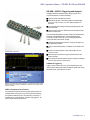
DPO4USB – USB 2.0 Triggering and Analysis
Debugging USB-based embedded system designs provides some complex
measurement and analysis challenges:
Capturing specific USB addresses and data
Displaying the elements of the USB message in an understandable
format, in a variety of formats, for a wide variety of engineers and
technicians
Time-correlating USB messages with analog and digital signals in the
embedded system
Capture long time windows of USB traffic and then find specific events
within the acquired data
The optional DPO4USB application module, installed in an MDO4000
or MSO/DPO4000 Series oscilloscope, provides a robust set of tools for
debugging embedded systems with USB 2.0 serial buses, including:
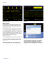
Triggering on a specific PID on an USB FS bus. A complete set of triggers, including
triggers for specific Token (address) and data packet content, ensures you quickly capture
your event of interest.
Automated serial triggering and decode for low-speed, full-speed, and
high-speed USB 2.0 signals
Trigger on all the critical elements of a USB bus such as address, data,
etc.
Decode all the critical elements of each USB message. No more
counting 1s and 0s!
Search through long acquisitions using user-defined criteria to find
specific messages
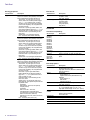
Event table shows decoded serial bus activity in a tabular, time-stamped
format for quick summary of system activity
USB 2.0 Serial Triggering
Trigger on packet content such as sync, reset, suspend/resume, token
(address) packets with specific address and endpoint, specific data content,
handshake packets, special packets, and errors.
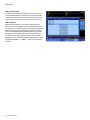
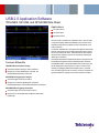
High-speed USB decoded display, automatically displaying bus content in any of several
digital formats.
USB 2.0 Decode
The DPO4USB USB Serial Application Module provides a higher-level,
combined view of the individual signals that make up the USB bus, making
it easy to identify where packets begin and end and identifying subpacket
components such as sync, PID, data, CRC, errors, etc.
Are you wasting time manually decoding the waveform? Tired of having
to visually inspect the waveform to count clocks, determine if each bit is
a 1 or a 0, combine bits into bytes, and determine the hex value? Let the
oscilloscope with a DPO4USB application module do it for you! Once you've
set up a USB bus, the MDO4000 or MSO/DPO4000 Series will decode each
packet on the bus, and display the value in Hex, Binary, or ASCII in the bus
waveform.
www.tektronix.com
5