1
Standard accessories
*1 The CD-ROM contains the operating instructions and different kinds of tool software programs.
*2 This label may be required for network management. The network administrator shall retain
the code label.
Included Installation Instructions
Network Camera
Model No.
Installation Guide (this document)............. 1 set
CD-ROM*1. ................................................ 1 pc.
Camera caution label................................ 1 pc.
Important Information................................ 1 pc.
Warranty card............................................ 1 set
Code label*2............................................... 1 pc.
Installation Guide
Making connections
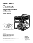
The following parts are used during installation procedures.
WV-SPV781L
I Wire lug fixing screw
M3 x 10 mm {3/8 inches}..................... 2 pcs.
(incl. 1 spare)
J Safety wire lug...................................... 1 pc.
K Protection cover.................................... 1 pc.
L Adapter box........................................... 1 pc.
M Mounting screws for adapter box (M5 × 20
mm {13/16 inches}).............................. 5 pcs.
(of them, 1 for spare)
N Adapter box mounting screw
(M4 × 35 mm {1- 3/8 inches})................ 1 pc.
A Camera mount bracket cover ........... 2 pcs.
B Camera mount bracket cover fixing screw
(M3 x 6 mm {1/4 inches}) .................... 3 pcs.
(incl. 1 spare)
C Waterproof tape ................................... 1 pc.
D LAN connector cover............................ 1 pc.
E 4P alarm cable ..................................... 1 pc.
F 2P power cable..................................... 1 pc.
G MONITOR OUT conversion plug*3........ 1 pc.
H Safety wire ........................................... 1 pc.
*3The audio/monitor output cable can be switched to be used as MONITOR OUT using the
software. The MONITOR OUT conversion plug is used to connect the camera to the audio/
monitor output cable and to convert a stereo mini jack (ø3.5 mm) {1/8 inches} into an RCA pin
output jack.
ACamera mount
bracket covers
(2 pcs.) (accessory)
Side B (Upper)
● This manual describes the installation procedures, network camera installation, cable
connections, and field-of-view adjustment.
● Before reading this manual, be sure to read the Important Information.
Side A (lower)
For Europe and other countries:
For U.S. and Canada:
Sunshield
Panasonic Corporation
Panasonic System Communications
Company of North America,
Unit of Panasonic Corporation
of North America
© Panasonic System Networks Co., Ltd. 2015
RJ45 (female)
Network cable
Camera
mount bracket
LAN cable
(category 5 or better, straight)
Power cable
(12 V DC)
12 V DC
(red)
GND
(black)
F 2P alarm cable
(accessory)
Camera
PGQX1821YA Cs0615-1075 Printed in China
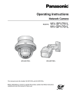
Major operating controls
The component names of the camera are as follows. Refer to the illustration when
installing or adjusting the camera.
Front cover
cover (installed)
NTSC/PAL switch
● Switches the MONITOR OUT terminal output between NTSC and PAL.
Note:
●● Use a thin, non-conductive tool to press the switch.
IMPORTANT:
Rating label
Dehumidifying
device
MONITOR OUT jack
(Video Out terminal
Default:
For NTSC monitor)
AF (Auto Focus)
button
*2
WIDE button
(The camera zooms out.)
*1 SDXC/SDHC/SD memory card is described as SD memory card.
*2 Depending on the scanning application used, the Data Matrix may not be
able to be read correctly. In this case, access the site by directly entering the
following URL.
http://security.panasonic.com/pss/security/support/qr_sp_select.html
●● When the camera is initialized, the settings including the network settings will be initialized.
Note that the CRT key (SSL encryption key) used for the HTTPS protocol will not be initialized.
●● Before initializing the settings, it is recommended to write down the settings in advance.
●● Do not turn off the power of the camera during the process of initialization. Otherwise, it may
fail to initialize and may cause malfunction.
SD ON/OFF button
1 When the SD ON/OFF button is pressed for less than 1 second, the SD MOUNT indicator is lit green
and data can be saved to the SD memory card*1.
2 When the SD ON/OFF button is held down for about 2 seconds, the SD MOUNT indicator goes out,
and the SD memory card can be removed.
SD MOUNT indicator
●● When an SD memory card is inserted and could
Lights off → Blinks green →
be recognized
Lights off
●● When data can be saved after the SD memory card is inserted Lights off → Lights green
and the SD ON/OFF button is pressed (for less than 1 second)
●● When data can be saved to the SD memory card
Lights green
●● When the SD memory card is removed after holding down
Lights green → Blinks green →
the SD ON/OFF button for about 2 seconds
Lights off (recording)
Lights green →
Lights off (waiting for recording)
●● When data cannot be saved to the SD memory card because Lights off
an abnormality was detected or the SD memory card is
configured not to be used
SD ERROR/AF indicator
●● When AF (Auto Focus) operation is being executed
●● When the camera is being started
●● When an SD memory card is recognized normally
●● When the SD memory card slot is not used or an abnormality
is detected in SD memory card after the camera has started
ACT indicator
●● When data is being sent via the network camera
LINK indicator
●● When the camera is able to communicate with the
connected device
Blinks red (about once per second)
Lights red
Lights red → Lights off
Lights red → Stays red
Blinks green (accessing)
Lights orange
Note:
Microphone/line input cable
Connect a stereo mini plug (ø3.5 mm {1/8 inches}).
●● Input impedance: Approx. 2 kΩ (unbalanced)
●● Recommended cable length: Less than 1 m {3.28 feet} (for microphone input) Less than
10 m {32.8 feet} (for line input)
●● Recommended microphone: Plug-in power type (option)
• Supply voltage: 2.5 V ±0.5 V
• Recommended sensitivity of microphone: -48 dB ±3 dB (0 dB=1 V/Pa,1 kHz)
●● Input level for line input: Approx. -10 dBV
Adequate waterproof treatment is required for the cables when installing the camera with cables
exposed or installing it under the eaves.
The camera body is waterproof, but the cable ends are not waterproof. Be sure to use the supplied waterproof tape at the points where the cables are connected to apply waterproof treatment
in the following procedure.
Failure to observe this or use of a tape other than the provided waterproof tape (such as a vinyl
tape) may cause water leakage resulting in malfunction.
<LAN cable>
C Waterproof tape (accessory)
Connect the power cable
●● A READILY ACCESSIBLE DISCONNECT DEVICE SHALL
BE INCORPORATED TO THE EQUIPMENT POWERED
BY 12 V DC POWER SUPPLY.
●● ONLY CONNECT 12 V DC CLASS 2 POWER SUPPLY (UL
1310/CSA 223) or LIMITED POWER SOURCE (IEC/EN/
UL/CSA 60950-1).
Power cable
12 V DC
Red Positive
Black Negative
●● Use 12 V DC power supply that is insulated from the commercial AC power.
●● Be sure to use the F 2P power cable (accessory) provided with this product.
●● Be sure to fully insert the F 2P power cable (accessory) into the 12 V DC power supply terminal. Otherwise, it may damage the camera or cause malfunction.
●● When installing the camera, make sure that excessive force is not applied to the
power cable.
●● Be sure to use an AC adaptor compliant with the specifications (written in the indication
label on the bottom side of this unit) regarding power source and power consumption.
Waterproof treatment for the cable joint sections
INITIAL SET button
● How to initialize the camera
Follow the steps below to initialize the network camera.
1 Turn off the power of the camera. When using a PoE hub, disconnect the LAN cable from the camera.
When using an external power supply, disconnect the 2P power cable plug from the camera.
2T
urn on the power of the camera while holding down the INITIAL SET button, and then keep holding
down the button for 5 seconds or more. About 2 minutes after you have released the INITIAL SET button, the camera will start up and the settings including the network settings will be initialized.
●● Be sure to use the E 4P alarm cable (accessory) provided with this product.
●● Install external devices so that they do not exceed the ratings above.
●● When using the external I/O terminals as the output terminals, ensure they do not
cause signal collision with external signals.
IMPORTANT:
LAdapter
box
(accessory)
IMPORTANT:
Connect the output cable of the AC adaptor to the F 2P power cable (accessory).
TILT lock screw
PAN lock screws
(2 pcs: The other is on the
opposite side)
<Ratings>
●● ALARM IN1 (DAY/NIGHT IN), ALARM IN2, ALARM IN3
Input specification: No-voltage make contact input (4 V - 5 V DC, internally pulled up)
OFF: Open or 4 V - 5 V DC
ON: Make contact with GND (required drive current: 1 mA or more)
●● ALARM OUT, AUX OUT (DAY/NIGHT OUT)
Output specification: Open collector output (maximum applied voltage: 20 V DC)
Open: 4 V - 5 V DC by internal pull-up
Close: Output voltage 1 V DC or less (maximum drive current: 50 mA)
* The default of EXT I/O terminals is “Off”.
Caution:
E 4P alarm cable
(accessory)
Alarm input/output cable
(External I/O terminal)
Authorised Representative in EU:
Yawing
lock screw
GND (black)
ALARM IN3, AUX OUT, DAY/NIGHT OUT (gray)
(Alarm input 3, AUX output, DAY/NIGHT switching output)
ALARM IN2, ALARM OUT (red) (Alarm input 2, Alarm output)
ALARM IN1, DAY/NIGHT IN (green) (Alarm input 1/ DAY/NIGHT switching input)
●● Off, input, and output of the external I/O terminal 2 and 3 can be switched by configuring the setting. Refer to the Operating Instructions on the provided CD-ROM for further
information about the external I/O terminal 2 and 3 (ALARM IN2, 3) settings (“Off”,
“Alarm input”, “Alarm output”, “AUX output” or “DAY/NIGHT switching output”).
Audio/monitor output cable (black)
KProtection
TELE button
(The camera zooms in.)
●● Use all 4 pairs (8 pins) of the LAN cable (category 5 or better, straight).
●● The maximum cable length is 100 m {328 feet}.
●● Make sure that the PoE device in use is compliant with IEEE802.3af standard.
●● When connecting both the 12 V DC power supply and the PoE device for power supply, 12 V DC will be used for power supply*.
*If a 12 V DC power supply and a PoE hub or router are used at the same time, network connections may not be possible. In this case, disable the PoE settings. Refer
to the operating instructions of the PoE hub or router in use.
*Depending on the PoE device used, if you stop the 12 V DC power supply after
operating it and a PoE hub or router at the same time, the power supply may stop,
causing the camera to restart.
●● When the LAN cable is disconnected once, reconnect the cable after around 2 seconds. When the cable is quickly reconnected, the power may not be supplied from
the PoE device.
●● When cables are used outdoors, there is a chance that they may be affected by lightning. In this case, install a lightning arrester just before where the LAN cable connects to the camera.
Panasonic System Networks Co., Ltd.
Fukuoka, Japan
Panasonic Testing Centre
Panasonic Marketing Europe GmbH
Winsbergring 15, 22525 Hamburg, Germany
5770 Ambler Drive, Mississauga,
Ontario, L4W 2T3 Canada
(905)624-5010
www.panasonic.ca
Two-dimensional
matrix barcode
(Data Matrix):
To our website
IMPORTANT:
Microphone/line input cable (white)
Panasonic Canada Inc.
E4P alarm cable (accessory)
Connect a LAN cable (category 5 or better, straight)
http://www.panasonic.com
www.panasonic.com/business/
For customer support, call 1.800.528.6747
Two Riverfront Plaza, Newark, NJ 07102-5490
SD memory card
slot
Turn off each system’s power supply before making a connection. Before making connections,
prepare the required peripheral devices and cables.
Camera
Arm
H Safety wire
(accessory)
Connect the alarm input/output cable
<Alarm input/output cable, power cable, microphone/line input cable, audio/monitor output
cable>
C Waterproof tape (accessory)
Connect an external amplifier-embedded speaker to the audio/
monitor output cable
Connect a stereo mini plug (ø3.5 mm {1/8 inches}).* *Use an external powered speaker.
●● Output impedance: Approx. 600 Ω (unbalanced)
●● Recommended cable length: Less than 10 m {32.8 feet}
●● Output level: -20 dBV (can switch to monitor output)
IMPORTANT:
●● Connect/disconnect the audio cables and turn on the power of the camera after turning off the power of the audio output devices. Otherwise, loud noise may be heard
from the speaker.
●● Make sure that the stereo mini plug is connected to this cable. When a monaural mini
plug is connected, audio may not be heard. When connecting a monaural speaker
with amplifier, use a locally procured conversion cable (mono-stereo).
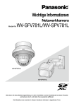
When connecting to a network using a PoE hub
Before starting the installation, check the entire system configuration.
The following illustration gives a wiring example of how to connect the camera to the network via
a PoE device (hub).
PoE device (hub)
Wind the tape in a
half-overlapping manner.
Wind the tape in a
half-overlapping
manner.
Analog monitor
PC
PC
IMPORTANT:
●● Also waterproof the F 2P power cable (accessory),
E 4P alarm cable (accessory), and external connections in the same way.
●● Stretch the tape to approx. twice its length (see the
illustration) and wind it around the cable. Insufficient
tape stretch causes insufficient waterproofing.
●● To prevent the LAN cable hook from coming loose
easily, fit the D LAN connector cover (accessory)
onto the pigtail cable as illustrated, and then slide it in
the direction indicated by the arrow. The connector of
the LAN cable used with this camera must meet the
following restrictions.
Height when inserted (From bottom to hook.):
Max. 16 mm {5/8 inches}
Connector width: Max. 14 mm {9/16 inches}
●● To install this product outdoors, be sure to waterproof
the cables.
Waterproof grade (IEC IP66 or equivalent) is applied
to this product only when it is installed correctly as
described in these operating instructions and appropriate waterproof treatment is applied.
The camera mount bracket is not waterproof.
Adjustment monitor
Powered
speaker
Stretch the tape to
approx. twice its length.
LAN cable
(category 5 or better, straight)
2x
D LAN connector cover
(accessory)
<Required cable>
LAN cable (category 5 or better, straight)
Use a LAN cable (category 5 or better, cross) when directly connecting the camera to a PC.
IMPORTANT:
The hook engages
with the connector
terminal
Microphone
●● The adjustment monitor is used to adjust the field of view when installing or servicing
the camera. It is not provided for recording/monitoring use.
●● Depending on the adjustment monitor, some characters (camera title, preset ID, etc.)
may not be displayed on the screen.
●● Use a switching hub or a router which is compliant with 10BASE-T/100BASE-TX.
●● If a PoE hub is not used, each network camera must be connected to a 12 V DC
power supply.
●● When using 12 V DC, power supply from a PoE hub or router is not required.
Step 4 Adjusting the camera 1, 2, 3, 4, 5
Installation
The installation tasks
are explained using
5 steps.
Step1
Step2
Preparations
Step3
Attaching the safety
wire
Step4
Fixing the camera
Step5
Adjusting the camera
Perform camera settings
(see the separate leaflet)
2Fit the Safety wire lug to the camera.
There are 3 methods to install the camera to a ceiling or wall as described below. Prepare the
required parts for each installation method before starting the installation. The following are the
requirements for the various installation methods.
Recommended
screw
Installation method
[1] Directly mount the camera onto the ceiling or wall
M5
(when there is a space for wiring in the ceiling or
screws x 4
the wall)
[2] Mount the camera to a junction box
* Only use metal junction boxes.
M4
screws x 4*2
[3] Mount the camera onto the ceiling or wall using the
M5
adapter box (approx. 510 g {1.13 lbs})
screws x 4
(when there is no space for wiring in the ceiling or the wall)
I Wire lug fixing screw
(accessory)
J Safety wire lug
(accessory)
724 N
{163 lbf}
(per 1 pc.)*1
724 N
{163 lbf}
(per 1 pc.)*1
724 N
{163 lbf}
(per 1 pc.)*1
IMPORTANT:
●● For the screws or anchor bolts used in the above methods ([1] to [3]), be sure to secure
the minimum pull-out strength of 724 N {163 lbf} per screw or bolt.
●● Select screws according to the material of the ceiling or wall that the camera will be
mounted to. In this case, wood screws and nails should not be used.
●● If a ceiling or wall board such as plaster board is too weak to support the total weight,
the area shall be sufficiently reinforced.
●● Because the front cover is temporarily removed when installing or adjusting the camera,
make sure no liquid enters the camera at these times.
Step 2 Attaching the safety wire
Step 3 Fixing the camera
[1]Directly mount the camera onto the ceiling or wall
Wire fitting
Wire mounting hole
J Safety wire lug
(accessory)
46 mm
{1-13/16 inches}
23 mm
{29/32 inches}
1 Determine the position where the camera is to be mountCable access
hole ø30 mm
ed on the ceiling or wall and drill a hole for securing the
{1-3/16 inches}
35
mm
camera and wiring as shown in the illustration to the right.
{1-3/8 inches}
* Determine the diameter and depth of the hole according to the
size of fixing screws or anchors (4 M5 screws, locally procured).
2 Connect the cables coming from the camera and com83.5 mm
{3-5/16 inches}
ing through the ceiling or wall according to the instructions in “Making connections”. Waterproof the connections according to the instructions in “Waterproof treatment for the cable joint sections”.
3 Secure the camera to the camera mount bracket by attaching the 2 upper M5 screws or anchors
(M5 x 4, locally procured) and then the 2 lower ones into the holes on side B on the camera mount
bracket in the order shown in the illustrations above explanations [1]-1 to [1]-3 in the lower left.
4 Secure the A camera mount bracket cover (accessory) to the camera mount bracket by
using M3 x 6 mm {1/4 inches} B Camera mount bracket cover fixing screws (accessory).
Note:
1 Pass the H safety wire (accessory) H Safety wire
(accessory)
through the wire mounting hole in
the J Safety wire lug (accessory).
Recommended tightening torque:
0.6 N·m {0.44 lbf·ft}
* The safety wire is not shown in the
subsequent illustrations.
Minimum pullout strength
*1 To mount the camera onto the ceiling or wall, the H safety wire (accessory)
must be attached. Have an M6 bolt and nut or anchor (with the minimum pullout strength of 724 N {163 lbf}) ready for securing the safety wire.
*2 Prepare a M4 screw with a washer with a diameter of 7.5 mm {5/16 inches} to
10 mm {3/8 inches} and a spring washer.
Direction in which
“↑TOP/FRONT” is pointed
●● When installing on a wall, install the
camera mount bracket so that “↑ TOP/
FRONT” faces upward.
●● When installing on a ceiling, install the
camera mount bracket so that “↑ TOP/
FRONT” is aligned with the direction in
which the camera is pointed.
Direction in which the
camera is pointed
Example: When mounting on a ceiling
[3] Mount the camera onto the ceiling or wall using the L Adapter box (accessory)
A Camera mount bracket cover (accessory)
23 mm {29/32 inches}
View from above (internal)
Camera
mount
bracket
2 PAN lock
screws
(the other one is
on the opposite
side)
6 mm {1/4 inches} wide x
10 mm {3/8 inches}
length hole
TO
P
B Camera mount
bracket cover fixing Screws x 4
(M5, locally
screws
procured)
(accessory)
Center of the adapter
box
L Adapter box
(accessory)
Cable access hole
(Used when connecting to a conduit.
Supports G3/4 parallel screws.)
M5 x 2
(locally procured)
[1]-1 Loosen the TILT lock
[1]-2 Loosen the 2 PAN [1]-3 Using the B camera mount
screw by about 1 turn until
lock screws about 1
bracket cover fixing screws
the camera faces downward
turn until the camera
(accessory), install the A
and then temporarily tighten
faces upward and use
camera mount bracket cover
the TILT lock screw. After
the 2 lower M5
(accessory) with the camera
this, use the 2 upper M5
screws (locally profacing downward.
screws (locally procured) to
cured) to secure the Recommended tightening torque:
secure the camera.
camera.
0.6 N·m {0.44 lbf ft}
*M5 x 4 screws, Minimum pull-out strength: 724 N {163 lbf} (per 1 pc.). Secure the
camera through the holes in side B of the camera mount bracket.
[2] Mount the camera to a junction box
As shown in the illustration to the right,
install the camera to a junction box using
4 M4 fixing screws (locally procured) via
the holes in side B of the camera mount
bracket. (Minimum pull-out strength:
724 N {163 lbf} (per 1 pc.))
83.5 mm
{3-5/16 inches}
Side B (upper) ↑ TOP/FRONT mark
46 mm {1-13/16 inches}
24.5 mm
{15/16 inches}
* The following explains an example of
Cable access hole
mounting the camera on a wall.
ø30 mm
{1-3/16 inches}
1 Secure the adapter box to the wall.
Step 3 Fixing the camera (continued from upper right)
TILT lock
screw
SD memory card
(Ensure that the label
faces the lens.)
IMPORTANT:
Step1 Preparations
M5 x 2
(locally
procured)
1 Change the direction the camera is facing from directly down to facing up (as shown in the illustration
on the lower right) and temporarily fix the camera in place. After this, loosen the 4 fixing screws on the
camera front cover and remove the front cover together with the K Protection cover (accessory).
Side B
(Upper)
46 mm
{1-13/16 inches}
Junction
box
N Adapter box mounting screw (accessory)
M4 × 35 mm {1- 3/8 inches}
hinges
↑TOP/FRONT mark
(on the front)
L Adapter box
(accessory)
Camera mount
bracket
M Mounting screws for
adapter box(accessory) x 4
A Camera mount
bracket cover (accessory) x 2
Note:
●● The procedure for fitting screws in the holes
for connections and fixing screws is the
same as for 2, 3, and 4 in [1] Directly
mount the camera onto the ceiling or wall.
●● When junction boxes or the like are used, it
is recommended that 2 pieces be used side
by side. (Securing the camera to one junction
box and making connections to the other
makes cable connections easy.)
83.5 mm
{3-5/16 inches}
Camera
mount bracket
Side A
(lower) B Camera mount
bracket cover fixing
screws (accessory)
x2
●● Drill pilot holes and a cable hole (see the illustration to the left for their dimensions). (Drill
pilot holes only if making connections through
the cable hole from the side.)
●● Be sure to face “TOP” inside the adapter box
upward.
●● Use 4 screws (locally procured) to directly secure
the adapter box to the wall. Minimum pull-out
strength: 724 N {163 lbf} (per 1 pc.)
●● To install this product outdoors, be sure to
waterproof the screws and their holes.
2 Temporarily secure the camera mount bracket
and camera to the adapter box.
●● After referring to [1]-1 and adjusting the camera to
face down, temporarily secure the camera, and then
use the M4 × 35 mm {1- 3/8 inches} N Adapter box
mounting screw (accessory) for installing the camera
to temporarily install the camera mount bracket to the
left or right hinge of the adapter box so that it can be
opened and closed.
●● Secure the camera mount bracket with “↑TOP/
FRONT” facing upward.
●● When the wall is on one side or the other,
install the adapter box to the hinge on the
opposite side of the wall.
●● Secure the camera mount bracket to the hinge
of the adapter box using the following tightening torque. Recommended tightening torque:
0.78 N·m {0.58 lbf·ft}
●● The front cover is connected to the camera via
the auxiliary wire for mounting the front cover
as well as the IR LED cable. Do not remove
the auxiliary wire and IR LED cable.
●● Do not remove the K Protection cover (accessory) from the front cover.
2 Fit a pin cable (locally procured) to the
MONITOR OUT jack on the camera and
connect an adjustment monitor.
Auxiliary
3 Turn on the camera.
wire
4 Insert an SD memory card into the slot, if necessary.
Front cover
Insert the SD memory card with its label facing the lens. Protection cover
●● To remove the SD memory card, hold down retaining tape
the SD ON/OFF button for about 2 seconds. K Protection cover
When the blinking SD MOUNT indicator goes (accessory)
out, you can remove the SD memory card.
●● After the SD memory card has been
Front cover fixing screws
replaced, press the SD ON/OFF button (for
less than 1 second), and make sure the SD * The front cover, including the cables and wires,
MOUNT indicator is continually lit.
and the front cover protector are not shown in
●● If you do not press the SD ON/OFF button after
the subsequent illustrations.
replacing the SD memory card, the SD MOUNT indicator is automatically lit approximately 5 minutes later.
5 Adjust the camera field of view.
Adjust the direction of the camera with the PAN, TILT and YAW parts, and press the
WIDE or TELE button until the desired field of view is achieved.
A)Using a 5 mm {3/16 inches} hex wrench (locally procured), loosen the PAN lock screw on
either side of the base of camera arm. To direct the camera to the left, turn the screw
clockwise when viewed from the front. To direct the camera to the right, turn it counterclockwise. (Panning range: + 180° to - 180°)
B)Using a 5 mm {3/16 inches} hex wrench (locally procured), loosen the TILT lock screw
in the center of camera arm and roughly adjust the direction of the camera. (Tilting
range: 0° to 115°)
C)Temporarily tighten 2 PAN lock screws and 1 TILT lock screw to prevent the camera
from moving.
IMPORTANT:
●● Avoid touching the tilting part near the warning label
when you change the tilting angle to secure the camera.
●● If the TILT or PAN lock screw is loosened, the camera
may not be held in place when it is secured to the
wall or ceiling. If this is the case, temporarily tighten
the appropriate lock screws to keep the camera from
moving.
Warning label
4 Secure the camera mount bracket to the
adapter box.
●● Using 4 M5 x 20 mm {13/16 inches} M
Mounting screws for adapter box (accessory),
secure the camera mount bracket to the
adapter box via the holes in side A of the camera mount bracket in the order of the top 2
holes to bottom 2 holes. Recommended tightening torque: 1.86 N·m {1.37 lbf ft}
(Refer to [1]-1 and [1]-2.)
●● Using 2 M3 x 6 mm {1/4 inches} B camera mount
bracket cover fixing screws (accessory), secure
the A Camera mount bracket cover (accessory)
to the Camera mount bracket. Recommended
tightening torque: 0.6 N·m {0.44 lbf ft}
F)Adjust the camera angle and field of view by repeating steps A) through E). When
the desired angle and field of view are achieved, tighten the 2 PAN lock screws,
TILT lock screw and Yawing lock screw.
Recommended tightening torque PAN lock screw: 2.7 N·m {2.0 lbf ft}
TILT lock screw: 4.3 N m {3.2 lbf ft}
Yawing lock screw: 2.7 N m {2.0 lbf ft}
IMPORTANT:
●● After adjustment, be sure to tighten the PAN, TILT and Yawing lock screws.
Note:
●● Any of the PAN, TILT and YAW lock screws can be adjusted by loosening them about
1 turn. Do not unscrew them more than necessary.
●● Make sure the camera is supported when loosening screws and adjusting the direction
of the camera.
●● When the image size is adjusted using the WIDE or TELE button, the camera focus is
adjusted accordingly by the auto-focus coarse adjustment function.
●● When the camera is mounted on the wall, adjust the camera direction by turning the PAN,
TILT and YAW parts as shown in the illustration below.
●● The range of angles that the camera can actually be turned to in regards to a wall or ceiling
is as follows.
Wall mounting
Angle
Ceiling mounting
Adjustment part
Angle
Adjustment part
Horizontal
±115°
TILT rotation
part*
±180°
PAN rotation
part
Vertical
±115°
TILT rotation
part*
0° to 115°
TILT rotation
part
Yaw
from -115° to
+200
YAW rotation
part
from -115° to
+200
YAW rotation
part
* You can change between horizontal and vertical angles by adjusting the PAN
rotation part.
* Do not adjust the PAN
rotation part more than
±180°. This may cause
cables to be wrenched.
TILT rotation part
PAN rotation part
YAW rotation part
Camera arm part
Tilt lock screw x 1 PAN lock screws
(The other one is on
Yawing
the opposite side) x 2
lock screw x 1
Step 4 Adjusting the camera (continued) 6, 7, 8, 9
6After adjusting the focus by pressing the AF
button, remove the adjustment monitor.
* The front cover, including cables and wires, and Protection
cover are not shown in the illustration.
7Attach the front cover.
IMPORTANT:
IMPORTANT:
●● Securely tighten the 4 front cover fixing
screws. Failure to do so may cause the camera to fall or waterproof failure.
Recommended tightening torque: 0.6 N·m
{0.44 lbf·ft}
Note:
●● When closing the front cover, be sure not to
allow the IR LED cable to be caught in the
cover.
●● Each M6 bolt and nut or anchor (locally procured) for securing the H safety wire (accessory) must have the minimum pull-out strength of 724 N {163 lbf}.
●● Be sure to secure the H safety wire (accessory) to the foundation of a structure or an
area that is strong enough.
●● Be sure to install the camera at least 2m 80 cm {9.2 feet} from the floor (the distance
between the lowest part of the installed camera and the floor).
●● When installing on a wall, secure the H safety wire (accessory) to an area above the
camera and the location where the camera is installed.
●● Attach the H safety wire so that if the camera were to become detached, it would not fall
on nearby people.
Auxiliary
wire
Front cover
Protection cover
retaining tape
K Protection cover
(accessory)
8Secure the H safety wire (accessory) to
the ceiling or wall.
9 Remove the K Protection cover (accessory).
Front cover fixing screws
■ When the camera is installed to the ceiling
Ceiling
Ceiling
●● Once the front cover is installed, the camera
may be slightly out of focus. After installing
the front cover and K Protection cover
(accessory), use the auto focus via the settings menu.
H Safety wire
(accessory)
M6 bolt and nut or anchor
(locally procured)
H Safety wire
(accessory)
■ When the camera is mounted on the wall
Wall
H Safety wire
(accessory)
When the camera has been installed, remove
the protection cover from the front cover. After
removal, be sure not to touch the clear part of
the front cover.
IMPORTANT:
3 Connect the cables.
●● Connect the cables coming from the camera and
coming through the wall according to the instructions in “Making connections”.
●● Waterproof the connections according to the
instructions in “Waterproof treatment for the
cable joint sections”.
D)Using a 5 mm {3/16 inches} hex wrench (locally procured), loosen the Yawing lock
screw, turn the camera until the sunshield faces up and adjust the tilt of the camera.
(Yaw range: -115° to +200°)
E)Press the WIDE or TELE button to adjust the field of view.
H Safety wire
(accessory)
M6 bolt and nut or anchor
(locally procured)
Wall
Clear part of the
front cover
K Protection cover
(accessory)
Note:
●● When removing the camera, perform removal by following the installation procedure in
the reverse order.
●● After the installation is complete, store the K Protection cover (accessory) for use during servicing.
Step 5 Configuring the settings of the camera (see the leaflet)
When the installation of the camera is complete, perform camera settings while
referring to the included “Configure the settings of the camera” (leaflet).