1
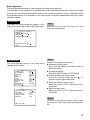
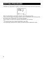
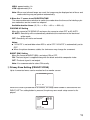
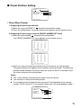
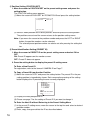
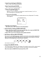
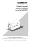
Operating Instructions Color CCTV Camera Model No. WV-CZ362E Before attempting to connect or operate this product, please read these instructions carefully and save this manual for future use. The model number is abbreviated in some descriptions in this manual. ABOUT THE USER MANUAL The operating instructions of the camera consist of 2 sets: these operating instructions (PDF) and Installaion Guide. This document explains how to configure the settings of the camera. Refer to the installation guide fo further information about how to install the camera. Adobe Reader is required to read PDF. When the Adobe Reader is not installed on the PC, download the latest Adobe Reader from the Adobe web site and install it. TRADEMARKS AND REGISTERED TRADEMARKS Adobe and Reader are either registered trademarks or trademarks of Adobe Systems Incorporated in the United States and/or other countries. 2 CONTENTS ABOUT THE USER MANUAL . . . . . . . . . . . . . . . . . . . . . . . . . . . . . . . . . . . . . . . . . . . . . . . . . .2 TRADEMARKS AND REGISTERED TRADEMARKS . . . . . . . . . . . . . . . . . . . . . . . . . . . . . . . .2 SETUP MENU . . . . . . . . . . . . . . . . . . . . . . . . . . . . . . . . . . . . . . . . . . . . . . . . . . . . . . . . . . . . . .4 SETTING PROCEDURE . . . . . . . . . . . . . . . . . . . . . . . . . . . . . . . . . . . . . . . . . . . . . . . . . . . . . .6 ■ Camera Setting . . . . . . . . . . . . . . . . . . . . . . . . . . . . . . . . . . . . . . . . . . . . . . . . . . . . . . . .7 ■ Preset Position Setting . . . . . . . . . . . . . . . . . . . . . . . . . . . . . . . . . . . . . . . . . . . . . . . . . .15 ■ Special Setting . . . . . . . . . . . . . . . . . . . . . . . . . . . . . . . . . . . . . . . . . . . . . . . . . . . . . . . .18 ■ Communication Setting . . . . . . . . . . . . . . . . . . . . . . . . . . . . . . . . . . . . . . . . . . . . . . . . .19 ■ Password Lock Setting . . . . . . . . . . . . . . . . . . . . . . . . . . . . . . . . . . . . . . . . . . . . . . . . . .20 3 SETUP MENU Performing each setting item in the setup menu should be completed in advance to use this unit. Perform the settings for each item in accordance with the conditions of the camera shooting area. Refer to the Operating Instructions (PDF) for further information. List of setup menu Setup item CAMERA CAMERA ID ALC/MANUAL SHUTTER AGC SENS UP SYNC WHITE BAL MOTION DET DNR RESOLUTION BW MODE PRIVACY ZONE AF MODE ZOOM LIMIT UPSIDE-DOWN MIRROR PRESET POSITION PRESET MAP HOME POSITION SELF RETURN IMAGE HOLD Description Performs the camera operation settings. This item specifies the camera title. The camera title that indicates the camera location and other information about the camera is created with alphanumeric characters and symbol, and displayed on the screen. Performs settings Light control. Specifies the electronic shutter speed. Specifies gain adjustment. Specifies electronic sensitivity enhancement. Specifies the synchronization type. Specifies white balance adjustment. Performs settings Motion Detector. Selects the level of the digital noise reduction function. Selects the resolution NORMAL or HIGH. Performs each setting regarding the black-and-white mode such as Switching between color and black-and-white images. Hides undesired portions in the camera shooting area. Select setting auto focus mode. A limitation is provided to prohibit the ZOOM operation in the direction of TELE, exceeding the preset value. The video image is reversed upside down during ON setting. The video image is reversed to the right and left during ON setting. Performs settings preset position. Select the position number. The preset setting menu appears on the monitor screen. The PRESET NUMBER SET menu appears on the monitor screen. To set a position number for the home position Set up the time needed to return to the home position automatically. The camera picture remains as a still image on the monitor screen until the camera reaches the preset position. SPECIAL CHROMA GAIN AP GAIN PEDESTAL PIX OFF ZOOM INVERSE FOCUS INVERSE REFRESH CAMERA RESET COMMUNICATION PASSWORD LOCK 4 Setting the Chroma Level. Setting the Aperture Level. Setting the Pedestal Level. This setting can assign a blemish position and compensate the blemish. The TELE/WIDE operation from the lens control terminal or the UP and DOWN buttons is reversed during ON setting. The FAR/NEAR operation from the lens control terminal or the UP and DOWN buttons is reversed during ON setting. The Refresh operation is started. The camera is reset to the factory default settings. Select RS485 or COAX or COAX (RCV). Performs settings password lock. Basic operation The description below explains how to operate the setup menu basically. The operations in the setup menu are performed with the operation buttons after calling up the setup menu on the connected video monitor. Refer to the installation guide for further information about the operation buttons. The operations in the setup menu can also be performed through the system controller (option). Screenshot 1 Hold down the setting button for approx. 2 seconds to call up the top screen of the setup menu. Step 1 Move the cursor to the item to be set, and press the setting button. ** WV-CZ362 SETUP ** CAMERA PRESET POSITION SPECIAL COMMUNICATION PASSWORD LOCK OFF END Screenshot 2 The selected setup screen in the setup menu appears on the screen. ** CAMERA SETUP ** 1/2 CAMERA ID OFF ALC/MANUAL ALC SHUTTER AUTO AGC ON(MID) SENS UP OFF SYNC INT WHITE BAL ATW1 MOTION DET OFF DNR LOW2 RESOLUTION NORMAL BW MODE ** CAMERA SETUP ** 2/2 PRIVACY ZONE OFF AF MODE STOP AF ZOOM LIMIT X 22 UPSIDE-DOWN OFF MIRROR OFF Step 2 Perform the settings for each item. ● Selection of setting item: Press the UP button or DOWN button to move the cursor. ● Change of settings: Press the RIGHT button or LEFT button. ● Display of advanced setup screen: Press the setting button when " " is attached to the target setting item. ● Return to previous setup screen: Move the cursor to "RET" and press the setting button. ● Return to top screen: Move the cursor to "TOP" and press the setting button. Step 3 RET TOP END To return to the camera image screen, move the cursor to "END" and press the setting button. 5 SETTING PROCEDURE Hold down the setting button for approx. 2 seconds to call up the top screen of the setup menu. ** WV-CZ362 SETUP ** CAMERA PRESET POSITION SPECIAL COMMUNICATION PASSWORD LOCK OFF END When the setting button is pressed for each item, each setting can be made. Setting can not be made if ON setting has been made for PASSWORD LOCK. Setting should be carried out after PASSWORD LOCK has been canceled. Refer to Page 20 in regard to the method of PASSWORD LOCK canceling. ● ● 6 To close the menu from Camera Setup buttons, select END. If no operation is performed for 6 minutes, the menu becomes automatically closed. ■ Camera Setting ● To Display the Camera Setup Menu Move the cursor to CAMERA menu appears. , and press the setting button. The CAMERA SETUP ** CAMERA SETUP ** 1/2 CAMERA ID OFF ALC/MANUAL ALC SHUTTER AUTO AGC ON(MID) SENS UP OFF SYNC INT WHITE BAL ATW1 MOTION DET OFF DNR LOW2 RESOLUTION NORMAL BW MODE ** CAMERA SETUP ** 2/2 PRIVACY ZONE OFF AF MODE STOP AF ZOOM LIMIT X 22 UPSIDE-DOWN OFF MIRROR OFF RET TOP END 1 Camera Identification Setting (CAMERA ID) You can use the camera identification (CAMERA ID) to assign a name to the camera. The camera ID consists of up to 16 alphanumeric characters. The camera ID display can be switched on or off on the monitor screen. To edit the CAMERA ID 1. Move the cursor to CAMERA ID. 2. The cursor on the letter “0” is highlighted. 3. Move the cursor to the character you want to edit. 4. After selecting the character, press the setting button. The selected character appears in the editing area. 5. Repeat the steps above until all characters are edited. CAMERA ID 0123456789 ABCDEFGHIJKLM NOPQRSTUVWXYZ ().,'":;&#!?= +-*/%$ÄÜÖÆÑÅ SPACE POSI RET RESET ................ To enter a blank space in the CAMERA ID Move the cursor to SPACE and press the setting button. To erase all characters in the editing area Move the cursor to RESET and press the setting button. All characters in the editing area disappear. 7 To determine the display position of the CAMERA ID 1. Move the cursor to POSI, and press the setting button. The display in the figure appears and the CAMERA ID is highlighted. 2. Move the CAMERA ID to the desired position. 3. Press the setting button to fix the position of the CAMERA ID. WV-CZ362 2 Light Control Setting (ALC/MANUAL) 1. Move the cursor to ALC/MANUAL and select ALC or MANUAL. When you select ALC, backlight compensation ON or OFF can be set. Note: The backlight compensation submenu associated with this menu is described separately and should be set up after installing the camera at the site and observing the actual site picture. 2. When MANUAL is selected, quit the setup menu. Press the OPEN or CLOSE button on the controller for iris adjustment. Note: The camera menu cannot be used for iris control. (1) ALC Mode with BLC ON ** ALC CONT ** BACK LIGHT COMP OFF BLC MASK SET LEVEL ••••|•••• + RET TOP END 1. Press the setting button after selecting ALC. The ALC CONT menu appears. ** ALC CONT ** BACK LIGHT COMP BLC ON LEVEL ••••|•••• + RET TOP END 2. Move the cursor to the BLC parameter and select ON. 3. If you want to adjust the video output level, adjust the “I” cursor for LEVEL. 8 (2) ALC Mode with BLC OFF 1. Move the cursor to BLC and select OFF. (When you select MANUAL, BLC is not available.) MASK SET appears on the menu. Blinking 2. To mask an area where backlight is bright, move the cursor to the area and press the setting button. The mask turns white. Repeat this procedure to mask the desired areas. Turns to white Blinking 3. To cancel a masked area, move the cursor to the area, and press the setting button. To delete all the masking area, press the RIGHT and LEFT buttons at the same time for more than 2 seconds. 4. After masking is completed, press the setting button more than 2 seconds. 48 mask areas on the monitor screen disappear and the ALC CONT menu appears. 3 Shutter Speed Setting (SHUTTER) OFF (1/50) 1/10 000 ● AUTO 1/4 000 1/120 1/2 000 1/250 1/500 1/1 000 In the AUTO mode, an object is clearly imaged under highlighted conditions by using the combination technology of iris and shutter functions. Note: When the selected shutter speed caused flicker on condition that fluorescent lamps stay on, change this setting to “OFF”. 4 Gain Control Setting (AGC) Select ON (LOW), ON (MID), ON (HIGH) or OFF. Notes: ● Even if AGC is set to ON and if the noise reduction function is enabled, after images may be produced by shooting a moving object. ● For more information, refer to Digital Noise Reduction on page 12. 9 5 Electronic Sensitivity Enhancement (SENS UP) The electronic sensitivity enhancement mode changes as follows: OFF X2 AUTO X16 AUTO X6 FIX ● X4 AUTO X32 AUTO X10 FIX X6 AUTO X2 FIX OFF X16 FIX X10 AUTO X4 FIX X32 FIX While the SENS UP function is selected, noise or spots may appear in the picture when the sensitivity of the camera is increased. This is a normal phenomenon. 6 Synchronization Setting (SYNC) The priorities of SYNC modes are assigned as follows: 1. Multiplexed vertical drive (VD2) 2. Internal sync (INT) Note: Whenever the vertical drive pulse (VD2) is supplied to the camera, the camera sync mode is automatically switched to the multiplexed vertical drive pulse (VD2) regardless of the selected sync mode. 7 White Balance Setting (WHITE BAL) 1. Auto-Tracing White Balance Mode (ATW1/ ATW2) The range of color temperature is ATW1 2 600 K-6 000 K ATW2 2 000 K-6 000 K * ATW2 is suited to setting when a sodium lamp is used. (1) The white balance of the camera is automatically adjusted at ATW1 and ATW2. ** ATW1 ** ••••|•••• + ••••|•••• + R B RET TOP END (2) For fine adjustment of ATW1/ATW2, press the setting button. The ATW1/ATW2 fine adjustment menu appears on the monitor screen. 2. Automatic White Balance Control Mode (AWC) In this mode, the supported color temperature range is approximately 2 500K to 8 000K. This mode is best in location where the light source is constant. (1) Select AWC n PUSH SET. (2) Press the setting button to start the white balance setup. PUSH SET is highlighted to indicate that white balance is being set. (3) PUSH SET returns to normal when balance setting is completed. (4) For fine adjustment of the AWC, move the cursor to AWC and press the setting button. The AWC fine adjustment menu appears on the monitor screen. ** AWC R B 10 RET TOP END ** ••••|•••• + ••••|•••• + 8 Motion Detector Setting (MOTION DET) 1. Select ON or OFF. 2. If ON is selected, press the setting button. The MOTION DETECT menu appears. You can mask the areas in this menu. 3. Move the cursor to MASK SET and press the setting button. 48 mask areas appear on the monitor screen. Refer to Light Control Setting on page 8 for masking operations. 4. After masking areas, press the setting button more than 2 seconds. The MOTION DETECT menu appears on the monitor screen. 5. Move the cursor to ALARM and select ON or OFF. ON: The alarm signal is supplied while the display mode is activated. OFF: The alarm signal is not supplied while the display mode is activated. 6. Move the cursor to DISPLAY MODE. Press the setting button to see the present setting. The areas that detect the motions blink. 7. Move the cursor to LEVEL. ** MOTION DET ** LEVEL DWELL TIME DISPLAY MODE ALARM MASK SET ••••|•••• + 2S OFF RET TOP END Obtain the optimum detection level. 8. Dwell Time Move the cursor to DWELL TIME, and select a time. When the time specified here elapses after motion detection, the camera will notify the connected device of the alarm activation. Selectable times (seconds): 2 s, 5 s, 10 s, 30 s. Important Notices: Motion detection should meet the following conditions. 1) The picture size on the screen should be larger than 1/48 of the actual picture size. 2) The contrast ratio between the object and the background picture should be more than 5% at the maximum detection level. 3) The time that takes the object to move from one end of the screen to the other should be more than 0.1 second. ● Also under the following conditions, mask or adjust the detection level to prevent malfunction. 1) When leaves, curtains, etc. are swayed by the wind. 2) When a picture has a high noise content due to low light conditions. 3) When the object is illuminated by lighting equipment that constantly turns on and off. ● 11 ● Alarm signal will take approx. 0.2 seconds to reach the alarm terminal of the VTR after the camera detects the object. Because the alarm signal is multiplexed on the video signal, it may be mistakenly interpreted by other video equipment as a time code signal. Therefore, when this camera is not used in a Panasonic Intelligent CCTV System, select OFF to prevent the above from occurring. 9 Digital Noise Reduction Setting (DNR) DNR may be used to improve quality under low light conditions. There are 4 levels of DNR, which may be selected depending on local site conditions. LOW1: DNR level is low. The after-image remains. LOW2: DNR level is low. The after-image is reduced. HIGH1: DNR level is high. The after-image remains. HIGH2: DNR level is high. The after-image is reduced. 0 Resolution Setting (RESLOUTION) Move the cursor to RESOLUTION and select NORMAL or HIGH. NOTE: When HIGH is selected, ringing will become much more clear. - Black and White Mode Setting (BW MODE) You can set up the black and white mode on this menu. BW Setting 1. Move the cursor to BW and select EXT, AUTO, ON or OFF. EXT: Changes between the color and BW mode according to the D/N IN terminal. AUTO: The camera selects the black and white mode if the picture is dark, or the color mode if the picture is bright enough. ON: The black and white mode is selected. OFF: The color mode is selected. Note: At the time of EXT setup, the controller cannot be used for ON/OFF control. 2. When AUTO is selected, it becomes possible to set up the LEVEL and the DURATION TIME. 3. Select HIGH or LOW for the threshold level at which the camera automatically switches to BW or color mode. The illuminance shown below is based on the assumption that the camera is used in an area lit by halogen lamps, and that AGC on the menu is set to MID. 12 HIGH: approximately 4 lx LOW: approximately 2 lx Note: When near-infrared lamps are used, the image may be displayed out of focus and mode switching may not perform automatically. 4. Move the “I” cursor to set DURATION TIME. The camera determines whether to switch the mode when the time set for holding a picture motionless on the screen has elapsed. Available duration times: (S) 10 s n 30 s n 60 s n 300 s (L) PIX SENS UP Setting Move the cursor to PIX SENS UP and move the cursor to select OFF or X2 AUTO. X2 AUTO: Sensitivity will be automatically doubled at the maximum in the black and white mode. OFF: Sensitivity will not be enhanced. Notes: “X2 AUTO” is not available when AGC is set to OFF. “X2 AUTO” is automatically set to OFF. ● When the picture becomes stable, the luminance may change for a moment. ● BURST (BW) Setting Move the cursor to BURST (BW), and select ON or OFF. ON: The burst signal is supplied along with the black and white composite video. OFF: The burst signal is not output. Note: It is recommended to select ON usually. = Privacy Zone Setting (PRIVACY ZONE) Up to 4 unwanted zones can be masked on the monitor screen. ** ZONE NUMBER 1 /4 ** RET TOP END When the cursor is positioned on a numeral, the setup zone number is selected with the RIGHT, LEFT or setting button is pressed, the privacy zone mask setup screen is displayed. ** ZONE NUMBER ZOOM/FOCUS POSITION SCALE 1 /4 PUSH PUSH PUSH ** SET SET SET SET DEL RET TOP END 13 Zoom/Focus Press the SET and then UP, DOWN, RIGHT or LEFT button to adjust the Zoom and Focus positions. Position Press the SET and then UP, DOWN, RIGHT or LEFT button to set up the mask position of the privacy zone. Scale Press the SET and then UP, DOWN, RIGHT or LEFT button to set up the mask size of the privacy zone. If there is the cursor in SET, press the setting button to reflect the contents of setup. Selecting DEL instead of SET deletes the zone settings and returns to the zone number selection menu. Note: If UPSIDE DOWN and MIRROR have been set up after the completion of privacy zone setup, there may be some displacement of the mask position. ~ Auto Focus Setting (AF MODE) MANUAL: In this mode, the AF mode activates when the setting button is pressed. STOP AF: If STOP AF is selected following MANUAL, the AF mode activates during or after lens operation. AUTO: If AUTO is selected following STOP AF, the AF mode activates when the illuminance is changed. Notes: Long use in AUTO mode may shorten the service life of the lens drive. ● When the electronic sensitivity enhancement (SENS UP) is activated except in the x2 FIX or x2 AUTO mode, this function is automatically set to MANUAL. ● The auto focus lens may not function properly in the STOP AF and AUTO mode under the following conditions. 1. Dirt or water on window glass. 2. Low lighting or illumination. 3. Bright objects or high intensity objects. 4. Single color object such as a white wall or fine felt 5. No center objects and sloping objects ● ! Zoom Limit Setting (ZOOM LIMIT) A limitation is provided to prohibit the ZOOM operation in the direction of TELE, exceeding the preset value. Optical zoom ranges from 1 to 22 magnifications, and electronic zoom becomes available for higher levels. @ Upside-Down Setting (UPSIDE-DOWN) The video image is reversed upside down during ON setting. # Mirror Setting (MIRROR) The video image is reversed to the right and left during ON setting. 14 ■ Preset Position Setting ** PRESET POSITION ** PRESET 1 MAP HOME POSITION OFF SELF RETURN OFF IMAGE HOLD OFF q e w r RET TOP END 1 Preset Menu Display 1. Displaying the preset menu directly (1) Move the cursor to PRESET 1 and select the position number. (2) Press the setting button. The preset setting menu appears on the monitor screen. 2. Displaying the preset menu from the PRESET NUMBER SET menu (1) Move the cursor to MAP and press the setting button. The PRESET NUMBER SET menu appears on the monitor screen. ** PRESET NUMBER SET ** 1* 2 3 5 6 7 9 10 11 13 14 15 17 18 19 21 22 23 25 26 27 29 30 31 ID:DOOR 33-64 RET TOP END 4 8 12 16 20 24 28 32 ** PRESET NUMBER SET ** 33 37 41 45 49 53 57 61 34 38 42 46 50 54 58 62 35 39 43 47 51 55 59 63 36 40 44 48 52 56 60 64 ID: 1-32 RET TOP END (2) Move the cursor to the position number to be set and press the setting button. The preset setting menu appears on the monitor screen(see below). To display any position number between 33 and 64, move the cursor to “33-64” in the lower left of the screen and press the setting button. Notes: ● The * mark indicates that the position number has been preset. ● The character H refers to the home position. ● The second line from the bottom shows the preset ID corresponding to the selected number. “DOOR” next to “ID” in the example shown right is for preset position number 1. PRESET NO. POSITION SET PRESET ID ALC/MANUAL AF MODE SCENE FILE 1 A ON ALC MANUAL OFF RET TOP END DEL B C D E F 15 A Position Setting (POSITION SET) 1. Move the cursor to POSITION SET on the preset setting menu and press the setting button. The POSITION setting menu appears. (1) Move the cursor to PUSH SET for ZOOM/FOCUS and press the setting button. ** POSITION 1 ** ZOOM/FOCUS PUSH SET RET TOP END (2) Select a zoom position and a focus position, and then press the setting button. The positions are set and the screen returns to the position setting menu. Note: If you move the cursor to the position number and press the LEFT or RIGHT button, the position number can be selected. The selected preset position number can also be set after pressing the setting button. B Preset Identification Setting (PRESET ID) 1. Move the cursor to PRESET ID on the preset setting menu and select ON or OFF. ON: Preset ID appears on the monitor screen. OFF: Preset ID does not appear. 2. Press the setting button to display the preset ID setting menu. To Enter a New Preset ID For registration, refer to the items of CAMERA ID on Page 7. To Copy a Preset ID from Another Position (1) Move the cursor to COPY and press the setting button. The preset ID in the preceding position is immediately shown. Each consecutive pressing of the setting button displays the ID preceding the one currently displayed. PRESET NO. 1* 0123456789 ABCDEFGHIJKLM NOPQRSTUVWXYZ ().,'":;&#!?= +-*/%$ÄÜÖÆÑÅ SPACE COPY POSI RET RESET DOOR............ (2) Display the most prospective ID. (3) Please see page 7 for the setting of Preset ID if you want to change it. To Enter the Next ID without Returning to the Preset Setting Menu (1) In the preset ID setting menu, move the cursor to the top line and select a desired position number. (2) Enter, copy, change or delete the ID as described above. 16 C Light Control Setting (ALC/MANUAL) Refer to Light Control Setting on page 8. D Auto Focus Setting (AF MODE) Refer to Auto Focus Setting on page 14. E Scene File Setting (SCENE FILE) 1. To set a scene file number Move the cursor to SCENE FILE and select a scene file number (1 to 10, or OFF). No scene file is selected at OFF. 2. To set scene file details Move the cursor to a scene file number and press the setting button. The setting menu appears. ** SCENE FILE 1 ** SHUTTER AGC SENS UP WHITE BAL MOTION DET AUTO ON(MID) OFF ATW1 OFF RET TOP END F Deleting Preset Positions Move the cursor to DEL and press the setting button. 2 Home Position Setting (HOME POSITION) 1. To set a position number for the home position Move the cursor to HOME POSITION and select a desired position number. 2. Select OFF if you are not using the home position function. 3 Self Return Setting (SELF RETURN) This menu is used to set up the time needed to return to the home position automatically. Move the cursor to SELF RETURN, select a return time from among the following and press the setting button to confirm your selection. 1MIN 2MIN OFF 3MIN 60MIN 5MIN 30MIN 10MIN 20MIN MIN stands for minute(s). 4 Image Hold (IMAGE HOLD) The camera picture remains as a still image on the monitor screen until the camera reaches the preset position. This function is useful for surveillance via local area network. Move the cursor to IMAGE HOLD and select ON or OFF. 17 ■ Special Setting ** SPECIAL SETUP ** CHROMA GAIN ••••|•••• AP GAIN ••••|•••• PEDESTAL ••••|•••• + PIX OFF ZOOM INVERSE OFF FOCUS INVERSE OFF REFRESH PUSH SET CAMERA RESET PUSH SET RET TOP END q e t u w r y i 1 Chroma Level (CHROMA GAIN) 2 Aperture Level (AP GAIN) 3 Pedestal Level (PEDESTAL) Move the cursor to CHROMA GAIN, AP GAIN and PEDESTAL and move the “I” cursor to your desired position. 4 PIX OFF Setting (PIX OFF) In this setting, you can assign a blemish position and compensate the blemish. 1. Move the cursor to PIX OFF and press the setting button. The PIX OFF menu appears. ** PIX OFF ** 1* 5* 2* 6* 3* 7* 4* 8 000 000 RET TOP END 2. Select a number and press the setting button. The blemish compensation position setting screen appears. Move the “+” cursor to the place on the blemish position. After moving the “+” cursor to a position where the blemish looks inconspicuous, press the setting button. Consequently, the blemish compensation position is set up and the PIX OFF menu is restored. After a blemish compensation position is set up, “*” is attached at the right of the number. 3. If you would like to delete a blemish compensation position, move the cursor to the applicable number and press the setting button. The blemish compensation position setting screen appears. + The blemish compensation position is deleted and “*” is also deleted from the right of the number by pressing the RIGHT and LEFT buttons for more than 2 seconds. 18 5 ZOOM INVERSE The TELE/WIDE operation from the lens control terminal or the UP and DOWN buttons is reversed during ON setting. 6 FOCUS INVERSE The FAR/NEAR operation from the lens control terminal or the UP and DOWN buttons is reversed during ON setting. 7 REFRESH Move the cursor to REFRESH and press the RIGHT and LEFT buttons at the same time for more than 2 seconds. Then, the Refresh operation is started. 8 CAMERA RESETTING (CAMERA RESET) Move the cursor to CAMERA RESET and press the RIGHT, LEFT, and SETTING BUTtons at the same time for more than 2 seconds. The camera is reset to the factory default settings. Notes: ● Any of the following cannot be reset to the factory defaults: Preset Position Setting (POSITION SET, PRESET ID, ALC/MANUAL, AF MODE, SCENE FILE), Communication Setting, Password Lock Setting, PIX OFF setting. ● In case of performing this operation on the condition that the cursor is positioned on other than CAMERA RESET, you cannot perform the operations on the menu thereafter. In that event, set the camera menu to ON again with the controller referring to page 15. ■ Communication Setting **COMMUNICATION SETUP** COMMUNICATION RS485 RET TOP END Move to the cursor to “COMMUNICTION” and select RS485 or COAX or COAX (RCV). COAX: Communication is carried out in the coaxial multiplex system. COAX (RCV): If our receiver (WV-RC100, WV-RC150, WV-RC170) is used, select COAX (RCV). RS485: Communication is maintained through the RS485 terminal. When RS485 is set up and the setting button is pressed, the RS485 setup screen is displayed. ● Changing the Camera Communication Parameters for RS485. ** RS485 SET UNIT NUMBER SUB ADDRESS BAUD RATE DATA BIT PARITY CHECK STOP BIT XON/XOFF WAIT TIME ALARM DATA DELAY TIME RET TOP END UP ** 1 –––– 19200 8 NONE 1 NOT USE OFF AUTO2 OFF 19 Move the cursor to the item and select the parameter. Unit Number In an RS485 chain each unit must have a unique number. Sub Address Do not set. Baud Rate Specifies the transmission speed (2 400, 4 800, 9 600, 19 200 bit per second) for the RS485 communication. Data Bit Specifies the number of data bits (7 or 8 bits) for the RS485 communication. Parity Check Specifies the parity check mode (NONE, ODD, EVEN). Stop Bit Specifies the number of stop bits (1 or 2 bits). X ON/X OFF Specifies whether to apply flow control or not (USE or NOT USE). Wait Time Specifies the time to wait until retrying after confirming that no data is received from the controller. (OFF: no retry, 100, 200, 400, 1 000 ms). Alarm Data Specifies the alarm transmission mode. POLLING: Transmits the alarm data in response to requests from the controller. AUTO 1: Transmits the alarm data each time an alarm signal is received by the camera. AUTO 2 (Default): Transmits alarm data at intervals of 5 seconds. Delay Time Specifies the time to transmit the acknowledge request when communicating on a 2-line connection. [----, 100 ms] Factory default setting: ---- (no set). This menu appears only when a 2-line communication is used. Make sure to be 100 ms when connecting the camera with the Video Multiplexer or the Matrix Switcher in a 2-line communication system. The settings become effective with the closing of SETUP menu. Note: Set the same parameters for the cameras, controllers and personal computers in an RS485 chain. ■ Password Lock Setting Caution: For security, do not operate your VTR for recording while the password menus are displayed on the monitor. A 3-digit number is used for a password to limit access to all settings. 20 1. Move the cursor to PASSWORD LOCK. ** PASSWORD? ** 0 1 2 3 4 5 6 7 8 9 . . . ↑ OK RESET NEW PASSWORD RET TOP END Note: ON or OFF can be selected only after going through the password verification. OFF: You can change all settings. ON: You cannot change all settings. 2. Press the setting button. Password Verification 3. The password verification menu appears. 3-1 Select a numeral for the first digit with the cursor, and press the setting button. Though the entered password is not displayed, the up-arrow moves one character to the right. 3-2 Repeat the above step for the 2nd and 3rd digits. Default: 123 3-3 The cursor moves to OK after all the three digits have been entered. Unless you want to change the password, press the setting button. If the correct password is entered, the screen returns to SETUP menu. ON and OFF settings are the same as made on the SETUP menu is as set in step 1. If a wrong password is entered, the screen returns to the verification menu. Repeat steps 3-1 to 3-3 to verify the password. 3-4 To cancel an incomplete password, move the cursor to RESET, and press the SET button. The screen returns to the verification menu. New Password 4. To change the password in step 3-3 above, move the cursor from OK to NEW PASSWORD, then press the setting button. NEW PASSWORD menu appears. ** NEW PASSWORD? ** 0 1 2 3 4 5 6 7 8 9 . . . ↑ . . . OK RESET RET TOP END Note: The NEW PASSWORD menu is accessible only after the verification has been completed. The up-arrow mark appears indicating the first digit on the first line. 4-1 Enter a new three-digit password in the same way as in steps 3-1 to 3-2. 4-2 The cursor moves to OK after all the three digits have been entered. Press the setting button to move the cursor to the first digit on the second line. 4-3 Enter the same password as the one you have entered on the first line. 4-4 The cursor moves to OK. Press the setting button. If the new password is successfully entered, the screen returns to SETUP menu. 4-5 Retry steps 4-1 to 4-4. If the first entry for the password is different from the second one, the screen returns to the NEW PASSWORD menu. 21 http://panasonic.net Importer's name and address to follow EU rules: Panasonic Testing Centre Panasonic Marketing Europe GmbH Winsbergring 15, 22525 Hamburg F.R.Germany © Panasonic System Networks Co., Ltd. 2010 sF0409-2010 3TR006208CZB Printed in China