1
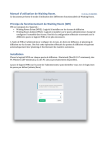
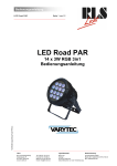
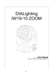
DIALighting COB Blinder 2x100W mkII USER MANUAL 1 1.BEFORE YOU BEGIN What is included l 1 x Fixture l 1 x Power cable with plug l 1 x User Manua Unpacking Instructions Immediately upon receiving a fixture, carefully unpack the carton; check the contents to ensure that all parts are present, and have been received in good condition. Notify the shipper immediately and retain packing material for inspection if any parts appear damaged from shipping or the carton itself shows signs of mishandling. Save the carton and all packing materials. In the event that a fixture must be returned to the factory, it is important that the fixture be returned in the original factory box and packing. AC POWER This fixture has an auto-switching switch-mode power supply that can accommodate a wide range of input voltages. The only thing necessary to do before powering on the unit is to make sure the line voltage you are applying is within the range of accepted voltages. This fixture will accommodate between 100V and 240V AC 50-60 Hz. Each light is connected end to end by the power socket “POWER IN” and “POWER OUT” on the light, or use the waterproof power cord. Please ensure the head and the tail tightening when connect the lights, to prevent the power leakage occurred by water seepage to the plug. Help preserve the environment! Ensure that this product is recycled at the end of its life. Your supplier can give details of local arrangements for the disposal of products. 2 Safety Instructions WARNING! ! Please read these instructions carefully, which includes important information about the installation, usage and maintenance of this product.. The following symbols are used to identify important safety information on the product and in this manual: ! DANGER! Safety hazard. Risk of severe injury or death DANGER! Hazardous Voltage. Risk of lethal or severe electric shock. WARNING! Fire hazard WARNING! LED light emission. Risk of eye injury. WARNING! Refer to user This light belongs to grade I protection device, therefore the light must connect = to the earth excellently. And the power connection must be operated by the professional technician. = Make sure that the working voltage will not higher or lower than the rated value. = Make sure that the cable didn't be damage or lacerated by sharp. = The light must be power off when it's standing idle or before clearing. = The cable must with plug, and you must pull out the cable by handle the plug. = Please be careful when installing the lighting. Never touch the bared cable, or it will cause the deadly electric shock. = Please use the suitable and safe cable to connect the light. = Please never remodel the light randomly, we will not take the guarantee for the faulty and damage which caused by dismantle、repair or remodel of the nonprofessional person. = Maximum ambient temperature 40°C. Do not operate fixture at temperatures higher than this. = Never connect the device to a dimmer pack. 3 2.INTRODUCTION Specifications Voltage Rating: AC100V~240V 50-60Hz Power Rating:200W LED Quantity: 2X100W 4-in-1COB LED(RGBW) LED: 600mA Beam Angle: 70° Ingress Protection: indoor Product Size: 432x133x220 mm N/W:4.4Kg Features RGBW color mixing with or without DMX controller Operating Modes: DMX512 Connection /Master & Slave... Bright large diode COB LEDs for vibrant colors Individual pixel control for pixel mapping options DMX Channels: 4/6/10/8/10/14 channels COL: RGBW control COL.S: Dimmer,RGBW, strobe STAGE: Dimmer, RGBW,strobe, color macro, auto, auto speed, ID PIX: RGBW pixel control, PIX.S:Dimmer, RGBW pixel control,strobe STAGE-2:Dimmer,RGBW pixel control,strobe,color macro,auto, auto speed, ID 4 Product Overview 5 3.SETUP Installation Requirement l This product can be used in a variety of situations, can hang and put on the ground. l If hanging the fixture for over head use, then please follow the below steps. l Please choose the suitable location to put or hang the light when installing it. You must use the exclusive clamp hanger and screw when hanging it, and make sure the weight of the light is within limits of the hanger. l Please make sure without any flammable objects within 0.5m when installing the light. l The installation should be operated by professional person; any irregular installation will cause the body injury or equipment damage. l Block access below the work area and use suitable and stable platform when installing or servicing fixture. Safety Cable Note: the cable must be secured through the heat sink ventilation passageway. Hanging Clamp Note: sold separately 6 Connection of DMX Signal Wire 1 2 3 Please use the fixture controller wire specially when use the DMX512 Controller. Connect the (male) 3 pin connector side of the DMX cable to the output (female) 3 pin connector of the first fixture. Connect the end of the cable coming from the first fixture which will have a (male) 3 pin connector to the input connector of the next fixture consisting of a (female) 3 pin connector. Then, proceed to connect from the output as stated above to the input of the following fixture and so on. This product can be connected numerous lamps in series without the need for the signal amplifier; the signal will not be weakened. DMX IN DMXOUT DMX IN DMXOUT DMX IN DMXOUT 3-PIN TO 5-PIN CONVERSION CHART Note! If you use a controller with a 5 pin DMX output connector, you will need to use a 5 pin to 3 pin adapter. 3 PIN TO 5 PIN CONVERSION CHART Conductor Ground/Shield Data ( - ) signal Data ( + ) signal Do not use Do not use 3 Pin Female(output) Pin 1 Pin2 Pin 3 5 Pin Male (Input) Pin 1 Pin2 Pin 3 Do not use Do not use 7 4.OPERATING INSTRUCTIONS Control Panel Functions In order to facilitate for inspection the signal, If the display to flicker when it's not receiving any signalNotes BUTTON MODE FUNCTION Exits from the current menu or function UP Navigates upwards through the menu list and increases the numeric value when in a function DOWN Navigates downwards through the menu list and decreases the numeric value when in a function ENTER Enables the currently displayed menu or sets the currently selected value in to the selected function 8 MAIN FUNCTION SUBFUNCTION 001~512 DMX ADDRESS CONTROL MODE STATIC COLOR Stage 10CH COL 4CH COL.S 6CH PIX 8 PIX.S 10 Stage 2 14 Dimmer 00~100 Red 1/Red 2 00~100 Green 1/Green 2 00~100 Blue 1/Blue 2 00~100 White 1/White 2 Strobe AUTO PERSONALITY Set DMX start address DMX 512 channel selection User can combine RED, GREEN, BLUE,WHITE to generate a custom color 00~100 No Function Static colours ST(01-10) Strobe speed 0-20 AUTO(01-10) Speed(00-20) Strobe speed 10 AUTO programs and speed available 10 Custome programs available Custome(01-10) ID Address 01-66 ID Switch ON~OFF Dimmer Speed INSTRUCTION SELECTION Assign ID address for fixtures Enable or disable ID Fast Fast dimming with unrestricted speed Smooth Smooth dimming with restricted speed Dimmer User can combine RED, GREEN, BLUE,WHITE to generate a custom Green 1/Green 2 color Custome Scene (1~10) (1~30) Blue 1/Blue 2 White 1/White 2 Red 1/Red 2 SCENE EDITOR 0~20Hz)Select strobe frequency Strobe (0~255) step time FADE INFO FACTORY SET TIME transition time of last step to current step Version VXXX CPU firmware version TEMP XX ℃ PCB temperature LOAD Return all settings to factory defaults 9 Master/Slave Control Mode 1、Setting master machine Acc ess control panel function by pressing MODE until 【AUTO 】 is displayed. Press ENTER, select 【AUTO】/【Custome】by pressing UP/DOWN buttons. Press ENTER, and then press MODE to exit. 2、Setting slave machine Access contro l panel function by pressing MODE until 【DMX ADDRESS】 is displayed. DMX512 Controller Mode 1、Setting DMX512 Address 【DMX ADDRESS】--【001--512】 Access control panel function by pressing MODE until 【DMX ADDRESS】 is displayed. Press ENTER, add or reduce channels by pressing UP/DOWN between 001 and 512. Press MODE to exit. 3、Setting Channels 【CONTROL MODE】--【4/6/10/8/10/14 channels】 Access control panel function by prekssing MODE until 【CONTROL MODE】 is displayed. Press ENTER button, select DMX channel by pressing UP/DOWN, Press MODE to exit. 10 DMX512 Channel Values 4/6/10 channels: COL COL.S Stage Value Description 1、 1、 000 - 255 Dimmer (0-100%) 1、 2、 2、 000 - 255 Red(0-100%) 2、 3、 3、 000 - 255 Green(0-100%) 3、 4、 4、 000 - 255 Blue(0-100%) 4、 5、 5、 000 - 255 White(0-100%) 0 - 19 20 - 24 25 - 64 65 - 69 70 - 84 85 - 89 90 - 104 105 - 109 110 - 124 125 - 129 130 - 144 145 - 149 150 - 164 165 - 169 170 - 184 185 - 189 190 - 204 205 - 209 210 - 224 225 - 229 230 - 244 245 - 255 Electronic shutter effect Shutter closed Shutter open Strobe 1 (fast --slow) Shutter open Strobe 2: opening pulse (fast--slow) Shutter open Strobe 3: closing pulse (fast--slow) Shutter open Strobe 4: random strobe (fast--slow) Shutter open Strobe 5: random opening pulse (fast -- slow) Shutter open Strobe 6:random closing pulse (fast-- slow) Shutter open Strobe 7: burst pulse (fast--slow) Shutter open Strobe 8: random burst pulse (fast--slow) Shutter open Strobe 9:sine wave (fast --slow) Shutter open Strobe 10: sine wave pulse(fast --slow) Shutter open 6、 6、 7、 000~009 No Function 010~255 Macro color control 11 COL COL.S Stage 、 8、 Description Value 000~009 010~019 020~029 030~039 040~049 050~059 060~069 070~079 080~089 090~099 100~109 110~119 120~129 130~139 140~149 150~159 160~169 170~179 180~189 190~199 200~225 No Function AUTO1 AUTO2 AUTO3 AUTO4 AUTO5 AUTO6 AUTO7 AUTO8 AUTO9 AUTO10 cust1 custom program 1 Cust2 custom program 2 Cust3 custom program 3 Cust4 custom program 4 Cust5 custom program 5 Cust6 custom program 6 Cust7 custom program 7 Cust8 custom program 8 Cust9 custom program9 Cust10 custom program10 9、 000~255 AUTO speed 10、 000~255 ID address selection 12 ID ADDRESS SELECTION VALUE FUNCTION VALUE FUNCTION VALUE 000~009 All Ids 212 ID23 235 FUNCTION ID46 010~019 ID1 213 ID24 236 ID47 020~029 ID2 214 ID25 237 ID48 030~039 ID3 215 ID26 238 ID49 040~049 ID4 216 ID27 239 ID50 050~059 ID5 217 ID28 240 ID51 060~069 ID6 218 ID29 241 ID52 070~079 ID7 219 ID30 242 ID53 080~089 ID8 220 ID31 243 ID54 090~099 ID9 221 ID32 244 ID55 100~109 ID10 222 ID33 245 ID56 110~119 ID11 223 ID34 246 ID57 120~129 ID12 224 ID35 247 ID58 130~139 ID13 225 ID36 248 ID59 140~149 ID14 226 ID37 249 ID60 150~159 ID15 227 ID38 250 ID61 160~169 ID16 228 ID39 251 ID62 170~179 ID17 229 ID40 252 ID63 180~189 ID18 230 ID41 253 ID64 190~199 ID19 231 ID42 254 ID65 255 ID66 200~209 ID20 232 ID43 210 ID21 233 ID44 211 ID22 234 Id45 13 8/10/14 channels: PIX PIX.S St-PIX 1、 1、 1、 Value 000 - 255 Description Dimmer (0-100%) 2、 2、 2、 000 - 255 Red 1 (0-100%) 3、 3、 3、 000 - 255 Green 1 (0-100%) 4、 4、 4、 000 - 255 Blue 1 (0-100%) 5、 5、 5、 000 - 255 White 1 (0-100%) 6、 6、 6、 000 - 255 Red 2 (0-100%) 7、 7、 7、 000 - 255 Green 2 (0-100%) 8、 8、 8、 000 - 255 Blue 2 (0-100%) 9、 9、 000 - 255 White 2 (0-100%) 0 - 19 20 - 24 25 - 64 65 - 69 70 - 84 85 - 89 90 - 104 105 - 109 110 - 124 125 - 129 130 - 144 145 - 149 150 - 164 165 - 169 170 - 184 185 - 189 190 - 204 205 - 209 210 - 224 225 - 229 230 - 244 245 - 255 Electronic shutter effect Shutter closed Shutter open Strobe 1 (fast --slow) Shutter open Strobe 2: opening pulse (fast--slow) Shutter open Strobe 3: closing pulse (fast--slow) Shutter open Strobe 4: random strobe (fast--slow) Shutter open Strobe 5: random opening pulse (fast -- slow) Shutter open Strobe 6:random closing pulse (fast-- slow) Shutter open Strobe 7: burst pulse (fast--slow) Shutter open Strobe 8: random burst pulse (fast--slow) Shutter open Strobe 9:sine wave (fast --slow) Shutter open Strobe 10: sine wave pulse(fast --slow) Shutter open 10、 10、 11、 000~009 No Function 010~255 Macro color control 000~009 No Function 12、 010~089 AUTO 01-10 090~255 custom program 01-10 13、 000~255 AUTO speed 14、 000~255 ID address selection 14 ID Address Instructions 1.Setting ID address 1、Access control panel function by pressing MODE until 【ID】 is displayed. 2、Press ENTER, increase or reduce ID values by pressing UP/DOWN between 01 and 66. 3、Press MODE to exit. 2. Enable or disable ID 【PERSONALITY】--【ID SWITCH】--【ON-OFF】 1、 Access control panel function by pressing MODE until 【PERSONALITY】 is displayed. 2、 Press ENTER, select by pressing UP/DOWN until is 【ID SWITCH】 displayed. 3、 Press ENTER, turn on or off ID addressing by pressing UP/DOWN buttons. 4、 Press MODE to exit. For every DMX512 address the user can set 66 separate ID addresses. ID addressing is a secondary function in DMX512 mode. In DMX512 Controller Mode, the user can simultaneously control the individual DMX address of all lights, and can control the lights which have separate ID address in independent DMX512. 15 DMX address:001 DMX address:001 DMX address:001 DMX Address:008 DMX Address:008 DMX Address:008 ID address:01 ID address:02 ID address:03 ID address:01 ID address:02 ID address:03 Select 10 channel on fixture's control panel (Please refer to DMX512 Channels Selection). The figure above shows a simple DMX layout which has used three units at each DMX address. The three units have different ID addresses. In the DMX address: 001, the user can control the first three lights simultaneously. When using channel 10select the channel number is 020-029 and ID Address=02, the controller can control the second light individually. When using channel 10 select the channel number is 000-010 and ID Address=00, all the lights are in common use at the same DMX address. 16