1
IUNION SWITCH & SIGNALl[fil]
SERVICE MANUAL 6488
A member of the ANSALDO Group
5800 CORPORATE DRIVE. PITTSBURGH, PA 15237
Description and Operation
CAB LINK
USER
MANUAL
for
Composite Cab Signal System
March, 1994
A-3/94-25-1
COPYRIGHT 1994 UNION SWITCH & SIGNAL INC.
PRINTED IS USA
CONTENTS
/
SECT TON
I
1.1
II
2.1
2.2
2.2.l
2.2.2
2.2.3
2.3
2.3.l
2. 3. 2
2.3.3
2. 3. 4
2.4
2.4.1
2. 4. 2
2.4.3
2.4.4
2.4.5
2.4.6
2.4.7
2.4.3
2.4.9
2. 4. :.o
2.5
2.5.1
2.5.2
2.6
2.7
III
3.1
3.2
3. 3
3.4
3.5
3.6
GENERAL DESCRIPTION . . . . . . . . . . . . . . . . . . . . . . . . . . . . . . . . 1-1
INTRODUCTION . . . . . . . . . . . . . . . . . . . . . . . . . . . . . . . . . . . . . . 1-1
OPERATION . . . . . . . . . . . . . . . . . . . . . . . . . . . . . . . . . . . . . . . . . . 2-1
GETTING STARTED . . . . . . . . . . . . . . . . . . . . . . . . . . . . . . . . . . . . 2-1
HOW TO USE IT . . . • . . . . . . . . . . . . . . . . . . . . . . . . . . . . . . . . . 2-1
t:renu Bar . . . . . . . . . . . . . . . . . . . . . . . . . . . . . . . . . . . . . . . . . . . 2 -1
Status Line . . • . . . . . . . . . . . . . . . . . . . . . . . . . . . . . . . . . . . . . 2-1
Dialog Boxes • • . . . • • . • . . . . . . . . . . . . . . . . . . . . . . . . . . . . . . 2-3
STATUS LINE FUNCTIONS . • . . . . . . . . . . . . . . . . . . . . . . . . . . . . 2-3
Exit . . . . . . . . . . . . . . . . . . . . . . . . . . . . . . . . . . . . . . . . . . . . . . 2 - 3
Print
. . . . . . . . . . . . . . . . . . . . . . . . . . . . . . . . . . . . . . . . . . . . 2-3
Help . . . . . . . . . . . . . . . . . . . . . . . . . . . . . . . . . . . . . . . . . . . . . . 2-3
Help Index . . . . . • . . . . . . . . . . . . . . . . . . . . . . . . . . . . . . . . . . 2-3
MENU BAR FUNCTIONS . . . . . . . • . . . . . . . . . . . . . . . . . . . . . . . . . 2-8
Filtering . . . . . . . . . . . . . . . . . . . . . . . . . . . . . . . . . . . . . . . . . 2-8
Serial • . . . . • . . . . . . . . . . . . . . . . . . . . . . . . . . . . . . . . . . . . . . 2-8
Set CAB Date and Time Clock . . . . . . . . . . . . . . . . . . . . . . . 2-8
Locomotive Unit Number . . . . . . . . . . . . . . . . . . . . . . . . . . . . 2-8
Date/Time Delta . . . . . . . . . . . . . . . . . . . . . . . . . . . . . . . . . . . 2-14
Upload . . . . . . . . . . . . . . . . . . . . . . . . . . . . . . . . . . . . . . . . . . . . 2-14
Review . . . . . . . . . . . . . . . . . . . . . . . . . . . . . . . . . . . . . . . . . . . . 2-14
Monitor . . . . . . . . . . . . . . . . . . . . . . . . . . . . . . . . . . . . . . . . . . . 2-23
Save Data . . . . . . . . . . . . . . . . . . . . . . . . . . . . . . . . . . . . . . . . . 2-28
Clear Events . . . . . . . . . . . . . . . . . . . . . . . . . . . . . . . . . . . . . . 2-28
KEYS
. . . . . . . . . . . . . . . . . . . . . . . . . . . . . . . . . . . . . . . . . . . . . 2-33
Menu Bar . . . . . . . . . . . . . . . . . . . . . . . . . . . . . . . . . . . . . . . . . . . 2 - 3 3
Status Bar . . . . . . . . . . . . . . . . . . . . . . . . . . . . . . . . . . . . . . . . 2-36
DIAGNOSTICS . . . . . . . . . . . . . . . . . . . . . . . . . . . . . . . . . . . . . . . . 2-36
DETAIL . . . . . . . . . . . . . . . . . . . . . . . . . . . . . . . . . . . . . . . . . . . . . 2-43
EVENT LOGS . . . . . . . . . . . . . . . . . . . . . . . . . . . . . . . . . . . . . . . . . 3 -1
},.PPLICATION EVENTS . . . . . . . . . . . . . . . . . . . . . . . . . . . . . . . . . . 3-2
LOGIC EVENTS . . . . . . . . . . . . . . . . . . . . . . . . . . . . . . . . . . . . . . . 3 -5
DECODER EVENTS . . . . . . . . . . . . . . . . . . . . . . . . . . . . . . . . . . . . . 3 - 7
TACH & TEST EVENTS . . . . . . . . . . . . . . . . . . . . . . . . . . . . . . . . . 3-10
VITAL INPUT #1 (#2) EVENTS . . . . . . . . . . . . . . . . . . . . . . . . . 3-11
VITAL OUTPUT EVENTS . . . . . . . . . . . . . . . . . . . . . . . . . . . . . . . . 3-12
SM 6488 Pg. i
SECTION I
GENERAL DESCRIPTION
1.1
INTRODUCTION
a.
Background
The UP/C&NW Composite MicroCab™ system maintains a log of
internal and external events.
Events are organized in a
functional hierarchy of event classes.
This hierarchy
allows informational events to be isolated from failure
events through independent classes.
Events from all classes are chronologically queued and
time-stamped within the MicroCabT~ unit's memory.
This
queue is of a fixed size and circular in nature such that
once it is filled, the oldest entries are deleted as new
encries are inserted.
The unit supports a serial data link to allow the most
recent events to be uploaded to a PC or dynamically
monitored via the PC. The event queue may be cleared
from either the PC or the front panel of the unit. Time
stamp information is only available through the serial
link.
b.
Description of Functions
The PC-based CABLINK program proviaes the means to look
at and clear the MicroCab™ system's event logs.
With
CABLINK, you can
- Upload the event log from the MicroCab™ system for
reviewing. This information can be saved to a disk
file for future review, if desired.
- Review an uploaded event log, saved to disk in an
event log file, using several filtering options.
- Print the uploaded events to a printer or disk file.
- Monitor the MicroCab™ system for new events.
In
this mode, each new event that occurs is uploaded
and displayed immediately on the PC screen. These
events can be saved to a disk file for future
review, if desired.
- Clear all events. Although the MicroCab™ event log
does not "fill up", it is sometimes better to clear
it out. This way, only new events show up when you
review the log.
- Set the Microcab™ system date/time clock to match
the PC's date and time.
SM6488, Pg. 1-1
'
THIS
PAGE
INTENTIONALLY
LEFT
BLANK
SM6488, Pg. 1-2
SECTION II
OPERATION
2.1
Getting started
The PC connects to a MicroCab™ unit with a serial communication
cable. The cable can be connected to the MicroCab™ unit at the
DB-9 connector located on the front panel of the N451910-0101 CPU
PC3 c~ the DB-9 connector located in the Remote Arm Box.
You can connect to serial port COMl or COM2 on the PC. The
soft~are defaults to serial port l, and can be changed while
runni~g the program.
C~..3LINK software is distributed on diskette. It may be run from
the diskette, or copied to the PC's hard disk. To install CABLINK
onto a hard disk, copy the contents of the distribution diskette
to the desired hard disk sub-directory.
Cl-..3LINK runs on IBM PC compatibles with a 720kb floppy drive.
mouse or trackball is supported, but not required.
2.2
A
3ow to use it
This section describes the mechanics of operating CABLINK. It
tells you how to select actions from the menu bar, how to quit
c;....3LINK, etc.
2.2.1
Menu Bar
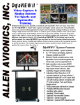
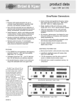
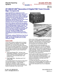
At the top of the screen you will see what is called the Menu Bar,
containing several choices (Figure 1). By selecting from these
choices, you can use CABLINK to access and inspect the event log
data on the CAB unit. You can also do things like change the date
and time on the CAB unit, or reconfigure the CABLINK side of the PC-to-CAB serial link.
To select an item on the Menu Bar, you can use either the keyboard
or the mouse. With the mouse, you click the left button when the
mouse cursor is over the item you want. on the keyboard, you
press the "Alt" key and the item's "hot key" together. The "hot
key" is for each item is highlighted. For instance, to select
"Serial", you press the "S" key while holding the "Alt" key down.
In the rest of this document, this key combination will be
referred to as ALT-S.
2.2.2
Status Line
At the bottom of the screen is the Status Line (Figure 1). This
area is used to display the current PC time and the current
revision level of the CABLINK program, and to show the hot keys
for Eelp and Exit.
SM6488, Pg. 2-1
Filter
Exit
Serial
Print
Time
Fl Help
Unit
Delta
Upload
Alt-Fl Help Index
Review
Monitor
CA.BLINK Rev O
Save
Clear
I
10:10:13
Figure 1
l
SM6488, Pg. 2-2
2.2.3
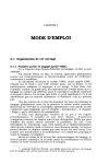
Dialog Boxes
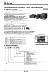
Sometimes CABLINK requires you to choose among several options.
Setting the event-viewing filters is one of these (Figure 2). In
these cases, you will be shown the available choices and asked to
select one or more of them. There are, again, two ways to do
this. The mouse can be clicked on the desired choice, or the
keyboard can be used. The "Tab" and arrow keys are used to move
the highlight from choice to choice. When the item you want is
highlighted, press the "Enter" key.
If you want to get out of the
Dialog Box without making any changes, press "Esc" or click on
"Cancel".
{See the "Keys" section for more information.)
2.3
2.3.1
STATUS LINE FUNCTIONS
Exit
Use this to quit the CABLINK program and return to DOS. If you've
uploaded data, but haven't yet saved it to a permanent disk file,
CABLINK will ask if you want to save it before exiting. Press
ALT-X or click the mouse on the Status Line where it says "Exit"
(Figure 1) .
2.3.2
Print
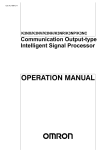
ALT-P pops up the Print Report dialog box. Use this feature if
you want to send the event log data to either a printer or a disk
file, in the same format as the Review display. If any viewing
Filters are set for the Review display, you can turn them off for
the report if you wish. (See Figure 3).
This function only works after you have done an UPLOAD, MONITOR,
or REVIEW, and uses the event data file from that previous
operation.
2.3.3
Help
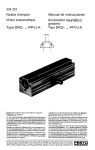
Context-sensitive help is available most of the time when running
CABLINK by pressing the Fl key. If no specific action is being
taken when Fl is pressed, "General" help will be displayed {Figure
4) •
For help on a specific topic, press ALT-Fl for the Help Topic
Index.
2.3.4 Help Index
The Help Topic Index gives you access to information on all
aspects of the CABLINK program. Press the ALT-Fl key combination
to pop up a scrollable list of available help topics {Figure 5).
Information on some help topics is available only via the Help
Topic Index.
SM6488, Pg. 2-3
Filter
Serial
Time
Dnit
Delta
Upload
Review
Monitor
Save
Clear
=(•]====== Viewing Filter Options
A ••• All Classes «
P ••• Application
L ••• Logic
D •.• Decoder
T ..• Tach & Test
l •.• Vital Input 1
( ) 2 ... Vital Input 2
[ ) V ••• Vital Output
»(
)
(X]
[ )
( )
( )
( )
Exit
Print
Fl Help
>[
Okay
)<
( cancel )
Alt-Fl Help Index
CABLINK Rev O
Figure 2
SM6488, Pg. 2-4
I
10:12:1s
Filter
Serial
Time
Unit
Unit
App
App
App
App
47
48
47
48
CPS
CPS
CPS
CPS
shutdown
shutdown
shutdown
shutdown
Delta Upload Review Monitor Save Clear
Reviewing Events ================================;,11
Press Escape when done
File: UP1234.DAT
due to failure of -1703 board
due to failure of -0404 board
d =[ • ] = Print Report
d
Print UP1234.RPT to:
(X) File
( ) Printer
08:33:49.3
08:33:49.3
08: 33: 51. 3
08:33:51.3
07-Feb-94
07-Feb-94
07-Feb-94
07-Feb-94
»Apply filters:
» (X) No 1c
( ) Yes
>[
OK
]<
[Cancel]
•
v
II
Exit
Print
Fl Help
Alt-Fl Help Index
CABLINK Rev O
Figure 3
SM6488, Pg. 2-5
15:27:06
)
Filter
Serial
Time
r-[•]
Unit
Delta
Upload Review Monitor Save Clear
Help =======================================;i1
Done J
Background•
The UP/C&NW Composite MicroCab system maintains a log of
internal and external events. Events are organized in a
functional hierarchy of event classes. This hierarchy
allows informational events to be isolated from failure
events through independent classes. Events from all
classes are chronologically queued and time-stamped
within the MicroCab unit's memory.
This queue is of
a fixed size and circular in nature such that once it
is filled, the oldest entries are deleted as new entries
are inserted. The unit supports a serial data link to
allow the most recent events to be uploaded to a PC or
dynamically monitored via the PC. The event queue may
be cleared from either the PC or the front panel of the unit.
The PC-based UPCABMON program provides the means to look at
Exit
Print
Fl Help
Alt~Fl Help Index
CABLINK Rev O
Figure 4
SM6488, Pg. 2-6
v
10:38:15
Filter
Serial
Time
Unit
Delta
Upload
Review
Monitor
Save
Clear
HELP INDEX
i=[.]
»Clear
Delta
Exit
Filter
General
Help
Help Index
I(
•
I
Okay]
Cancel
v
I
Exit
Print·
Fl Help
Alt-Fl Help Index
CABLINK Rev O
Figure 5
(
SM6488, Pg. 2-7
10:38:39
2.4
!-~
2.4.1
BAR FUNCTIONS
Filtering
You can either look at ALL the recorded event information in a
given data file, or you can filter out selected parts of it.
The
viewing filter options are:
a) Look at all events, bl Look at all events of a given class (or
classes).
To control the filtering options, you first press ALT-F, or click
the mouse on the "Filter" menu bar item. A dialog box will pop
up, showing the current filter settings (Figure 2).
To select or
de-select a given item, press the key corresponding to the
highlighted letter for that item. For example, press the 'A' key
to selecc "All Classes", and then press it again to DE-select "All
Classes".
Repeated pressing of the same key toggles that filter
item on and off. When you have the filters set the way you want
them, press 'O' (for "Okay") or click on the "Okay" button with
the mouse.
If you change your mind and don't want to change them,
press 'Esc" (or click on "Cancel"), and any changes just made will
be discarded.
2.4.2
Serial
The Serial Communications Port defaults to the PC's COMl.
You can
change ic to COM2 and back again with this menu choice (ALT-S,
Figure 6) .
2.4.3
)
Set CAB Date and Time Clock
The C_:'.J3 date/time clock can (will) be set to match that of the PC
("Time", ALT-T, Figure 7). CABLINK asks you to confirm that you
want co set the CAB clock, and then does so if you respond in the
affi-::-mative.
Bear in mind that the CAB date/time will be set to
match that on the PC you have connected to it, regardless of
whether the PC has the correct date & time.
2.4.4
Locomotive Unit Number
The Unit Number is used to create a PC file name, where the
uploaded event log data will be stored. Unless you specifically
override it, CABLINK will name permanent data files "nnnn.DAT",
where the "nnnn" is the Locomotive Unit Number.
A valid Locomotive Unit Number must be entered before you UPLOAD
or MONITOR MicroCab™ events.
If needed, CABLINK will prompt you
to enter one (Figure 8). To be considered a valid unit number, it
must be four digits (Figure 9). Thus, "1" should be entered as
0001·.
11
If yo'..l wish to change the Unit Number, (when uploading event logs
from another locomotive, for instance), select the "Unit" option
from the Menu Bar (ALT-N, Figure 10).
SM6488, Pg. 2-8
)
Filter
Serial
Time
Unit
Delta
=[•)========
,, (X)
(
)
Upload
Review
Monitor
Save
Clear
Serial Port
1. •• COMl «
>[
OK
]<
2 ••• COM2
Cancel)
=
Exit
Print
Fl Help
Alt-Fl Help Index
CABLINK Rev O
Figure 6
SM6488, Pg. 2-9
10:39:03
Filter
Serial
Time
Unit
Delta
=[•]=====
Upload
Confirm
Review
Monitor
Save
Clear
=========n
Microcab system date & time will be
set to match the PC. Okay to
continue?
»[
Exit
Print
Fl Help
OK
]«
[Cancel)
Alt-Fl Help Index
CABLINK Rev O
I
10:34:06
Figure 7
).
SM6488, Pg. 2-10
Filter
Serial
Time
Unit
Delta
Upload
Review
Monitor
Save
Clear
rr========= Locomotive Unit Number=========;,
»Unit Number:
!!!!!!ilm!
Exit
Print
Fl Help
>[
OK
]<
Alt-Fl Help Index
[ Cancel]
CABLINK Rev O
Figure 8
SM6488, Pg. 2-11
I
10:4o:s9-
Filter
Serial
Time
Unit
Delta
Upload
Review
Monitor
Save
Clear
=(•)=========== Error
Locomotive Unit Number must be four
digits.
»[
Exit
Print
Fl Help
OK
Alt-Fl Help InJex
) 11
CABLINK Rev O
Figure 9
SM6488, Pg. 2-12
I
10:41:s3
Filter
Serial
Time
Unit
Delta
Upload
Review
Monitor
Save
Clear
rr======= Locomotive Unit Number======~
»Unit Number:
5050
>[ OK
]<
[ Cancel]
Exit
Print
Fl Help
Alt-Fl Help Index
CABLINK Rev O
Figure 10
./
SM6488, Pg. 2-13
10:41:28
2.4.5
~ate/Time Delta
Normally, events will be stored and displayed on the PC with an
adjustej date & time. That is, the time stamp as received from
the CAB unit will be adjusted to match the time frame on the PC.
If you do not want this "normalization" to occur, use the "Delta"
option {ALT-D) to turn this function off.
(NOTE: This option acts
as a toggle.
If you turn it OFF, you can turn it back ON with the
same Me~u 3ar item, "Delta".) See Figures 11 and 12.
2.4.6
:Jpload
Before you can review them, you must upload the events stored in
the Microcab™ from the MicroCab™ to the PC (Figure 13).
CABLINK
puts t~em in a temporary file.
If you want to, you can save them
in a permanent event log file on the PC. That way you can view
them again later.
If you choose NOT to save to a permanent event
log file, the next upload will overwrite the current one.
You
will be asked if you want a permanent event log file when the
upload ends.
Press ALT-U or click on "Upload" to start.
While the upload is in progress, the display will show the class
and code of the event record just received, as a progress
indicator, so you can see that something is happening (Figure 14).
You can cancel the upload, if you want, by pressing any key.
If a cc:nrnunication error occurs during an upload, an error message
will be logged on the PC, and the upload will be resumed, if
possible.
Thus, if you are viewing the event data file, and you
see the c..z:._BLINK Serial Comm Error event in the event log, this
means ~hat at that point in the event log there may have been one
or more CA3 events that were not successfully received by CABLINK.
If, af~er several tries to re-establish communication, CABLINK
still cann~t talk to the CAB unit, a diagnostic information
message will be displayed, and the upload will be terminated ( see
Figure 15 ) .
II
II
If the event log on the Microcab™ unit is empty, a message to that
effect will be displayed (Figure 16).
2.4.7
:\eview
Use this to look at event data you got from the MicroCab™ unit.
This can be data you just uploaded (with UPLOAD), or data you
previously uploaded at some point in the past. When you select
"Reviev.·" from the Menu Bar (by pressing ALT-R), you will be asked
to choose a name for the disk file where the event data is stored
(Figure 17). You can either enter a name of your own choosing (by
typing it in), or select an existing data file.
To select a data
file, press enter, to move the highlight down to the file list.
Then use the arrow keys to move the highlight around from name to
name, until the file you want to review is highlighted (Figure
18) . Now press "Enter".
SM6488, Pg. 2-14
Filter
Serial
Time
Unit
Delta
Upload
Review
Monitor
Save
Clear
= [ • ] = = = = = Confirm =========ii
DATE/TIME DELTA Usage Is Now OFF.
Do You Want To Turn It ON?
»[
Exit
Print
Fl Help
OK
]«
[Cancel]
Alt-Fl Help Index
CABLINK Rev O
Figure 11
SM6488, Pg. 2-15
10:39:41
)
Filter
Serial
Time
Unit
Delta
Upload
Review
Monitor
Save
Clear
=[•]==========Confirm===============;,
DATE/TIME DELTA Usage Is Now ON.
Do You Want To Turn It OFF?
»[
OK
] cc
[Cancel]
)
Exit
Print
Fl Help
Alt-Fl Help Index
CABLINK Rev O
Figure J2
SM6488, Pg. 2-16
I
10:40:12
Filter
Serial
Time
Unit
Delta
Upload
Review
Monitor
Save
Clear
=[•]========== Confirm ===============n
UPLOAD Current Events From CAB
Unit?
»[
Exit
Print
Fl Help
OK
]
cc
[Cancel]
Alt-Fl Help Index
CABLINK Rev O
Figure 13
SM6488, Pg. 2-17
10:26:12
)
Filter
Serial
Time
Unit
Delta
Upload
Review
Monitor
Save
Clear
~~~~~~~-Upload~~~~~~~~
Uploading...
Exit
Print
Fl Help
006
Alt-Fl Help Index
CABLINK Rev O
Figure 14
SM6488, Pg. 2-18
I
10:21:01
Filter
Serial
Time
Unit
Delta
Upload
Review
Monitor
Save
Clear
==[. )====== Error================;,
Cannot Communicate With MicroCab
Unit.
11 [
Exit
Print
Fl Help
OK
Ja
Alt-Fl Help Index
CABLINK Rev O
Figure 15
SM6488, Pg. 2-19
10:28:50
Filter
Serial
Time
Unit
Delta
.=[•)====
Upload
Review
Monitor
Save
Clear
Information = = = = = = =
CAB Event Log is Empty
»[
Exit
Print
Fl Help
OK
Alt-Fl Help Index
]«
CABLINK Rev·o
I
10:29:s1
Figure J.6
)
SM6488, Pg. 2-20
Filter
Serial
[
Time
Unit
Delta
.
Upload
Review
>[ Open
Files
>UPOOOO.DAT
UP0009.DAT
UP1010.DAT
UPllll.DAT
UP1234.DAT
UP2221.DAT
UP2222.DAT
UP2222A.DAT
... .
.....
<
UP2222C.DAT
UP2222D.DAT
UP2222Q.DAT
UP2222Z.DAT
UP2223.DAT
UP2224.DAT
UP2227.DAT
UP2323.DAT
Clear
Fl Help
]<
[Cancel ]
...:...... ·. ·.. ·. ·=···:...:...:..··:···:···:·~·-:-;=.·:}=:/;: >
P:\UPCABMON\SOURCE\*.DAT
UPOOOO.DAT
3484
Feb 03,1994
Print
Save
Read File
]
»Name
*.DAT
Exit
Monitor
Alt-Fl Help Index
10:0Ba
CABLINK Rev O
Figure 17
SM6488, Pg. 2-21
10:30:39
Filter
Serial
Time
Unit
Delta
Upload
Review
Monitor
Save
Clear
[•]============== Read File
Name
UP2223.DAT
»Files
UPOOOO.DAT
UP0009.DAT
UP1010.DAT
UPllll.DAT
UP1234.DAT
UP2221.DAT
UP2222.DAT
UP2222A.DAT
<i!
>[ Open
•
UP2222C.DAT
UP2222D.DAT
UP2222Q.DAT
UP2222Z.DAT
»UP2223.DAT
UP2224.DAT
UP2227.DAT
UP2323.DAT
(Cancel ]
((
>
P:\UPCABMON\SOURCE\*.DAT
UP2223.DAT
4212
Feb 07,1994
Exit
Print
Fl Help
]<
Alt-Fl Help Index
08:56a
CABLINK Rev O
Figure 18
SM6488, Pg. 2-22
I
10:31:31
The logged event information is presented as shown in Figure 19.
The first column is the event Class, then the event Code within
the Class. Descriptive text for that specific event is next,
followed by the time and date when the event occurred. Note that
the most recent events are at the bottom of the list, and that the
viewer screen is automatically scrolled to the bottom when first
displayed (Figure 19). You can use the arrow keys, PageUp and
PageDown, Ctrl-PageUp and Ctrl-PageDown to move up and down within
the listed events.
You can either look at ALL the recorded event information in a
given data file, or you can filter out selected parts of it. The
viewing filter options are:
a) Look at all events
b) Look at all events of a given class (or classes)
To control the filtering options, you first press ALT-F, or click
the mouse on the "Filter" menu bar item. A dialog box will pop
up, showing the current filter settings (Figure 20). To select or
de-select a given item, press the key corresponding to the
highlighted letter for that item. For example, press the 'A' key
to select •All Classes", and then press it again to DE-select "All
Classes". Repeated pressing of the same key toggles that filter
item on and off. When you have the filters set the way you want
them, press •o• {for "Okay") or click on the "Okay" button with
the mouse. If you change your mind and don't want to change them,
press 'Esc" (or click on "Cancel"), and any changes just made will
be discarded.
If you have been reviewing data from the most recent upload, and
you wish to save it under a different file name, select the "Save"
option from the Menu Bar (Figure 21). The file name defaults to
the current locomotive unit number+ ".DAT", but you can change
the filename.
If you wish to review another set of data, select the "Review"
option from the Menu Bar again. As before, you will be asked to
choose a name for the disk file where the event data is stored.
2.4.8
Monitor
Monitoring is used to see new events as they occur. To activate,
press ALT-M. Any existing event log data will be uploaded to the
default file UPLOAD.DAT, and simultaneously displayed on the
screen (Figure 22). Then CABLINK will sit and wait for any new
events that occur on the CAB unit, which will then be uploaded and
displayed as they occur. The display of existing and new events
is done according to the selected filtering options. When
finished, you will be asked whether you want to save the events to
a permanent event log file on disk (Figure 21).
SM6488, Pg. 2-23
Filter
Serial
Time
Unit
Delta Upload Review
Reviewing Events
Press Escape when done
Monitor
Save
Clear
r.================================
Unit 5050
VIN2
VOD
App
App
Lgic
Tach
VINl
VIN2
VOD
03
03
47
48
27
03
03
03
03
VPA type register error
VPA type register error
CPS shutdown due to failure of -1703 board
CPS shutdown due to failure of -0404 board
Timeout on decoder message transmission
VPA type register error
VPA type register error
VPA type register error
VPA type register error
II
File: UP2223.DAT
08:41:52.3
08:41:52.3
08:52:55.3
08:52:55.3
08:52:55.3
08:52:55.3
08:52:55.3
08:52:55.3
08:52:55.3
07-Dec-94
07-Dec-94
07-Dec-94
07-Dec-94
07-Dec-94
07-Dec-94
07-Dec-94
07-Dec-94
07-Dec-94
)
•
v
II
Exit
Print
Fl Help
Alt-Fl Help Index
CABLINK Rev O
11:28:30
Figure 19
)
SM6488, Pg. 2-24
/
f
Filter
Serial
Time
Unit 5050
r
VOD
App
App
Lgic
Tach
VINl
VIN2
VOD
App
App
Lgic
Tach
VINl
VIN2
VOD
App
App
Lgic
Tach
03
47
48
27
03
03
03
03
47
48
27
03
03
03
03
47
48
27
03
Unit
Delta Upload Review
Reviewing Events
Press Escape when done
Monitor
save
Clear
II
File: UP2223.DAT
VPA type register error
08:37:25.3
CPS shutdown due to failure of -1703 board
08:41:04.3
Viewing Filter Options
CPS =[.]
1:04.3
Time
1:04.3
C<
» [X] A••• All Classes
VPA
1:04.3
VPA
[X] P ••• Application
>[ Okay ]<
1:04.3
VPA
[ ] L ••• Logic
1:04.3
VPA
1:04.3
[ ] D••• Decoder
CPS
[ ] T ••• Tach & Test
1:07.3
CPS
[ ] 1. •• Vital Input 1
1:07.3
[ Cancel ]
Time
1:07.3
[ ] 2 ••• Vital Input 2
VPA
[ ] V••• Vital Output
1:07.3
VPA
1:07.3
VPA
1:07.3
VPA type register error
08:41:07.3
CPS shutdown due to failure of -1703 board
08:41:15.3
CPS shutdown due to failure of -0404 board
08:41:15.3
Timeout on decoder message transmission
08:41:15.3
VPA type register error
08:41:15.3
•
07-Dec-941
07-Dec-94•
07-Dec-94
07-Dec-94
07-Dec-94
07-Dec-94
07-Dec-94
07-Dec-94
07-Dec-94
07-Dec-94
07-Dec-94
07-Dec-94
07-Dec-94
07-Dec-94
07-Dec-94
07-Dec-94
07-Dec-94
07-Dec-94
07-Dec-94v
II
Exit
Print
Fl Help
Alt-Fl Help Index
CABLINK Rev O
Figure 20
SM6488, Pg. 2-25
10:32:38
Filter Serial Time Unit Delta Upload Review Monitor Save Clear
r.=============================== Reviewing Events ================================;i
~
File: UP2223.DAT
Press Escape when done
Unit 5050
VOD
App
App
Lgic
Tach
VINl
VIN2
VOD
App
App
Lgic
Tach
VINl
VIN2
VOD
App
App
Lgic
Tach
03
47
48
27
03
03
03
03
47
48
27
03
03
03
03
47
48
27
03
08:37:25.3
VPA type register error
08:41:04.3
CPS shutdown due to failure of -1703 board
08:41:04.3
CPS shutdown due to failure of -0404 board
4.3
Time o=( •)
Save Event Log Data
VPA
»Path & Filename:
4.3
VPA
UP2223.DAT
( Cancel]
4.3
>[ OK
]<
4.3
VPA
VPA 1==================================================~4.3
CPS shutdown due to failure of -1703 board
08:41:07.3
08:41:07.3
CPS shutdown due to failure of -0404 board
08:41:07.3
Timeout on decoder message transmission
VPA type register error
08:41:07.3
08:41:07.3
VPA type register error
VPA type register error
08:41:07.3
08:41:07.3
VPA type register error
CPS shutdown due to failure of -1703 board
08:41:15.3
CPS shutdown due to failure of -0404 board
08:41:15.3
Timeout on decoder message transmission
08:41:15.3
VPA type register error
08:41:15.3
07-Dec-941
07-Dec-94•
07-Dec-94
07-Dec-94
07-Dec-94
07-Dec-94
07-Dec-94
07-Dec-94
07-Dec-94
07-Dec-94
07-Dec-94
07-Dec-94
07-Dec-94
07-Dec-94
07-Dec-94
07-Dec-94
07-Dec-94
07-Dec-94
07-Dec-94v
II
Exit
Print
Fl Help
Alt-Fl Help Index
I·
CABLINK Rev O
I
10:33:14
Figure 21
)
SM6488, Pg. 2-26
Filter
Serial
Time
Unit 5050
Unit
Delta Upload Review
Monitoring Events
Press Escape when done
Monitor
Save
Clear
•
App
App
Lgic
Tach
VINl
VIN2
VOD
App
App
47
48
27
03
03
03
03
47
48
CPS shutdown due to failure of -1703 board
CPS shutdown due to failure of -0404 board
Timeout on decoder message transmission
VPA type register error
VPA type register error
VPA type register error
VPA type register error
CPS shutdown due to failure of -1703 board
CPS shutdown due to failure of -0404 board
10:34:36.3
10:34:36.3
10:34:36.3
10:34:36.3
10:34:36.3
10:34:36.3
10:34:36.3
10:34:38.3
10:34:38.3
09-Feb-94
09-Feb-94
09-Feb-94
09-Feb-94
09-Feb-94
09-Feb-94
09-Feb-94
09-Feb-94
09-Feb-94
v
Exit
Print
Fl Help
Alt-Fl Help Index
CABLINK Rev O
Figure 22
SM6488, Pg. 2-27
10:34:47
2.4.9
Save Data
If you want to save the current event log file to a different
name, select the "Save" menu bar option (ALT-A, Figure 23). This
enables you to type in a new name for the file, including a path
name.
)
If you want to save the uploaded data to a diskette, put the
diskette drive letter in the file name, like this A:UP1234.DAT
You can enter up to 80 characters in the path name, although you
can only see 11 at any time (Figure 24).
If the name you enter already exists (Figure 25), you can choose
either to overwrite the old one, or enter a new, different name.
2.4.10
Clear Events
This function {ALT-C) clears ALL events logged in the Microcab™
system's event log {Figure 26). The filtering options have no
effect on this operation, and it cannot be aborted once begun.
CABLINK Kill ask you to confirm your intent to clear the logs
before proceeding.
)
)
SM6488, Pg. 2-28
Filter
Serial
Time
Unit
Delta
Upload
Review
=[•]
Save Event Log Data
»Path
&
Filename:
....................................
;;;;;;;;;;;;;;;;;;;;;;;;;;;;;;;;;;;;
> [ OK
J<
Exit
Print
Fl Help
Alt-Fl Help Index
Monitor
Save
Clear
[ Cance 1 J
CABLINK Rev O
Figure 23
SM6488, Pg. 2-29
10:35:32
---)
Filter
Serial
Time
Unit
Delta
Upload
Review
Save Event Log Data
»Path & Filename:
<ce\UPSOSOb.D> >[ OK
)<
,==[•)
Monitor
Save
Clear
================;i
[ Cancel]
)
Exit
Print
Fl Help
Alt-Fl Help Index
CABLINK Rev O
I
10:36:ss
Figure 24
)
SM6488, Pg. 2-30
Filter
Serial
•]
[
Time
Unit
Delta
Upload
Review
Monitor
Save
Clear
Alert
UP5050.DAT already exists.
[ Overwrite ]
11 [
New name
]«
=
Exit
Print
Fl Help
Alt-Fl Help Index
CABLINK Rev O
Figure 25
SM6488, Pg. 2-31
10:35:57
Filter
Serial
Time
Unit
Delta
Upload
Review
Monitor
Save
Clear
=[•)==============Confirm================;,
ALL event logs on the MicroCab unit
will be cleared! Okay to continue?
»[
Exit
Print
Fl Help
OK
)«
[Cancel)
Alt-Fl Help Index
CABLINK Rev O
Figure 26
SM6488, Pg. 2-32
I
10:31:s1
2.5
KEYS
2.5.1
Menu Bar:
Alt_F ..... Filter - set viewing filters
Alt_S ..... Serial - change serial port
Alt_T ..... Time - set CAB date/time to match PC's
Alt_N ..... Unit - change locomotive unit number
Alt_D ..... Delta - turn CAB time normalization ON/OFF
Alt_U ..... Upload - get event logs from CAB unit
Alt_R ..... Review - look at uploaded event logs
Alt_M ..... Monitor - simultaneously upload and view events
Alt_A ..... Save - save current event log data to disk
Alt_C ..... Clear - Clear CAB unit's event logs
a.
Filter:
A ........... All Classes
P ........... Application
L . . . . . . . . . . . Logic
D ........... Decoder
T ........... Tach & Test
1. .......... Vital Input 1
2 ........... Vital Input 2
v ........... Vital Output
0 ........... Okay
C ........... Cancel
Esc ......... Cancel
Tab ......... Move highlight
Enter ....... Select highlighted item
Space Bar ... Select highlighted item
b.
Serial:
K • . • . . . . . . . . Okay
Esc ......... Cancel
highlight
Tab ......... Move
Enter ....... Select highlighted item
Space Bar ... Select highlighted item
c.
Time:
K •.••.•••.•• Okay
Esc ......... Cancel
Tab ......... Move
highlight
Enter ....... Select highlighted item
Space Bar ... Select highlighted item
SM6488, Pg. 2-33
d.
Unit:
0 ........... Okay
c ........... Cancel
)
Esc ......... Cancel
digits O through 9 (when working in "Unit Number:"
field) Tab ......... Move highlight
Enter ....... Select highlighted item
Space Bar ... Select highlighted item
e.
Delta:
K •.•....•..• Okay
Esc ......... Cancel
Tab ......... Move highlight
Enter ....... Select highlighted item
Space Bar ... Select highlighted item
f.
Upload:
K ••.•....•.• Okay
Tab ......... Move highlight
Enter ....... Select highlighted item
Space Bar ... Select highlighted item
During upload, pressing ANY key aborts
g.
Review:
Read File:
Name:
Enter .... display file(s) which match pattern in
"Name"
Letters and digits, in "Name" field
Tab ...... moves highlight to "Files" list
Files:
arrow keys move highlight
Tab ..... moves highlight to "Okay" button
Enter ... selects highlighted file name
Esc ..... Cancel
o ....... Open selected file
Viewer:
Esc ... Cancel
Up Arrow, DownArrow
Page Up, Page Down
Home, End
Ctrl_Page Up, Ctrl_Page Down
SM6488, Pg. 2-34
)
h.
Monitor:
Esc ... Cancel
UpArrow, DownArrow
Page Up, Page Down
Home, End
Ctrl_Page Up, Ctrl_Page Down
i.
Save:
K ........... Okay
Esc ......... Cancel
Tab ......... Move highlight
Enter ....... Select highlighted item
Space Bar ... Select highlighted item
In the "Save As" field:
Letters and numbers
Enter
Tab
j.
Clear:
K • . • . . . . • . . • Okay
Esc ......... Cancel
Tab ......... Move highlight
Enter ....... Select highlighted item
Space Bar ... Select highlighted item
;'
k.
Print:
Esc .......... Cancel
o ............ Okay,printreport
•
Enter ........ Accept current settings
P ............ Send to Printer
F ............ Send to File
Y ............ Yes, apply viewing Filters to the
report
N ............ No, don't apply viewing
Filters to the report
Arrow keys ... Change selected option
Tab .......... Changes highlighted dialog
box section
Ctrl_Page Up, Ctrl_Page Down
SM6488, Pg. 2-35
2.5.2
Status Bar:
Alt_X ..... Exit - quit running CABLINK, return to DOS
Alt_Fl .... Help Index - index of all help topics
Fl . . . . . . . . Help - context-sensitive help
a.
Help:
D ..... Cancel (Done)
~sc ... Cancel
UpArrow, DownArrow
?age Up, Page Down
Home, End
b.
Help Index:
0 . . . . . . . . . . . Okay
c ........... Cancel
Esc ......... Cancel
Tab ......... Move highlight
Enter ....... Select highlighted item
Space Bar ... Select highlighted item
Cursor keys (arrows, PgUp, PgDn, Home, End) scroll
list of topics
2.6
)
DIAGNOSTICS
If an error condition occurs, CABLINK will automatically attempt
to correct it.
If the error can not be corrected automatically,
you will be advised of the error and given as much practical
advice as possible on correcting it.
a.
Locomotive Unit Number must be four digits - You entered
something other than four numeric digits.
For example:
RIGHT
WRONG
0001
0101
1234
9999
1
101
ab3e
<nothing>
When CABLINK is started, you must enter a valid Unit Number
before you can continue (Figure 9).
b.
Error writing to XXXXXXXX.XXX. Disk may be full. CABLINK was unable to write as much data as it tried to,
during the "Save" function. Check to see if the target
disk or diskette is full (Figure 27).
SM6488, Pg. 2-36
)
c.
Cannot open XXXXXXXX.XXX for writing. - During "Save"
function, the target file could not be opened. See if
diskette is write-protected or not inserted fully (Figure
2 8) .
d.
Critical disk error on drive X - This message appears on
the Status Line, and usually results from trying to write
to a read-only diskette (Figure 29)).
e.
Disk is not ready in drive X - Status Line message,
diskette may not be fully inserted (Figure 30).
f.
Could not open UCM.HLP for reading. - Help topics are
loaded when CABLINK is started. If there is a problem
with this, it may mean that the help file is missing
(Figure 31) .
SM6488, Pg. 2-37
)
Filter
Serial
Time
Unit
Delta
Upload
Review
Monitor
Save
Clear
=[•]========== Error =================s1
Error writing to a:UP5050.DAT.
Disk may be full
II [
OK
] I(
)
Exit
Print
Fl Help
Alt-Fl Help Index
CABLINK Rev O
I
10:47:2a
Figure 27
)
SM6488, Pg. 2-38
Filter
Serial
Time
Unit
Delta
Upload
Review
Monitor
Save
Clear
=[ • ) = = = = = Error ==========;i
Cannot open a:UPSOSO.DAT for
writing
II [
Exit
Pr.i.nt
Fl Help
OK
] Cl
Alt-Fl Help Index
CABLINK Rev O
Figure 28
!
(¥
SM6488, Pg. 2-39
I
10:49:10.
Filter
Serial
Time
Unit
Delta
Upload
Review
Critical disk error on drive a
Monitor
Save
Enter Retry
Figure 29
SM6488, Pg. 2-40
Clear
Esc Cancel
I
I
Filter
Serial
Time
Unit
Delta
Upload
Review
Disk is not ready in drive a
Monitor
Save
Enter Retry
Figure 30
SM6488, Pg. 2-41
Clear
Esc Cancel
Filter
Serial
Time
Unit
Delta
=[•)===========
Upload
Review
Monitor
Save
Clear
Error
Could not open UCM.HLP for reading.
I) [
OK
] cc
l
.Exit
Print
. Fl Help
Alt-Fl Help Index
CABLINK Rev O
I
11 :06: 4a
Figure 31
l
SM6488, Pg. 2-42
2.7
l
Detail
The data file, as stored on disk, is not intended to be viewed
directly. The following information is provided for troubleshooting purposes only.
Certain data are prefaced by a keyword, denoted by a "%" prefix.
The keywords currently in use are:
%UNIT ........ Locomotive unit number, entered by user
%PCCLOCK ..... The PC date and time the data file was written
%CABCLOCK: ... The CAB date and time when the upload started
%DELTA: ...... The difference between the PC date/time
and the CAB date/time
Each Event record contains several fields, as follows:
cc ee hh:mm:ss.t dd-mmm-yy
is the Event Class
CC
"ee" .......... is the Event code
"hh:mm:ss.t" ... is the time the event occurred
"dd-mmm-yy" ... is the date the event occurred
II
H
•
•
•
•
•
•
•
•
•
•
•
The time and date in each record will be saved with the %TIMEDELTA
parameter applied, unless you had turned this off in Setup before
the upload.
A typical data file will look like this:
%UNIT9090
%PCCLOCK: Dec 15 11:24:52 1993
%CABCLOCK: Dec 15 11:24:51 1993
%DELTA: 1
00 47
08:41:23.3
17-Dec-93
00 48
08:41:23.3
17-Dec-93
08:41:23.3
01 27
17-Dec-93
08:41:23.3
17-Dec-93
03 03
04 03
08:41:23.3
17-Dec-93
17-Dec-93
05 03
08:41:23.3
06 03
17-Dec-93
08:41:23.3
00 47
11:23:56.3
17-Dec-93
00 48
11:23:56.3
17-Dec-93
(and so on)
SM6488, Pg. 2-43
THIS
PAGE
INTENTIONALLY
LEFT
)
BLANK
)
SM6488, Pg. 2-44
SECTION III
EVENT LOGS
Failure event classes have counters associated with each event
which may be viewed from the front panel. Event counters may be
cleared from either the PC or the front panel. Informational
event classes cannot be viewed from the front panel but are only
accessible through the serial data link. This approach provides
the feature that a unit operating without any failures will not
report any events when interrogated from the front panel. Events
are only reported on the front panel if failures have been
detected.
The following classes of events are logged by the MicroCab™ unit:
a. APPLICATION (Event Class 0): Informational events related to
transitions of specific I/0 points and operational
conditions.
b. LOGIC (Event Class 1): Failure events related to the
operational software and hardware of the Logic Sub-system CPU
PCB.
c. DECODER (Event Class 2): Failure events related to the
operational software and hardware of the Decoder Sub-system
CPU and Analog Input PCBs.
r
d. TACH & TEST (Event Class 3):
Tach & Test PCB hardware.
Failure events related to the
e. VITAL INPUT PCB 1 (Event Class 4): Failure events related to
Vital Input PCB hardware. Specific to the Input PCB
associated primarily with C&NW inputs.
f. VITAL INPUT PCB 2 (Event Class 5): Failure events related to
Vital Input PCB hardware. Specific to the input PCB
associated primarily with UP inputs.
g. VITAL OUTPUT PCB (Event Class 6):
Vital Output Driver PCB hardware.
Failure events related to
SM6488, Pg. 3-1
3.1
APPLICATION EVENTS
This class of informational events is related to transitions of
specific I/0 points and operational conditions.
Within the APPLICATION class the following informational events
are detected and logged by the system.
Event
1
2
3
4
5
6
7
8
9
10
11
12
13
14
15
16
17
18
19
20
Descriotion
UP cab signal cu tin. Result of transition of UP
CUTOUT switch from CUTOUT to CUTIN position.
UP cab signal cutout. Result of transition of UP
CUTOUT switch from CUTIN to CUTOUT position.
UP cab signal partial cutout. Result of pull and
release of the UP partial cutout switch. Indicates
ooerator reauest, not necessarily system operation.
UP departure test switch on. Result of transition of
UP deoarture test switch from OFF to ON position.
UP departure test switch off. Result of transition of
UP departure test switch from ON to OFF position.
UP EPV output on. Result of transition of the UP EPV
out out from OFF to ON state.
UP EPV output off. Result of transition of the UP EPV
output from ON to OFF state.
UP upgrade to APPROACH aspect. Result of an aspect
chanoe from RESTRICTED.
UP upgrade to APPROACH MEDIUM aspect. Result of an
asoect chanqe from RESTRICTED or APPROACH.
UP upgrade to CLEAR aspect. Result of an aspect
chanoe from RESTRICTED, APPROACH, or APPROACH MEDIUM.
UP downgrade to RESTRICTED aspect. Result of an
aspect change from CLEAR, APPROACH MEDIUM, or
APPRO.?>..CH.
UP downgrade to APPROACH aspect. Result of an aspect
chanoe from CLEAR or APPROACH MEDIUM.
UP downgrade to APPROACH MEDIUM aspect. Result of an
asoect chanoe from CLEAR.
Reserved.
C&NW cab signal cutin. Result of transition of C&NW
CUTOUT switch from CUTOUT to CUTIN position.
C&l-rw cab signal cutout. Result of transition of C&NW
CUTOUT switch from CUTIN to CUTOUT position.
C&NW arm switch activated. Result of push and release
of C&NW ARM switch. Indicates operator request, not
necessarilv svstem ooeration.
C&NW departure test switch on. Result of transition
of C&NW deoarture test switch from OFF to ON oosition.
C&NW departure test switch off. Result of transition
of C&NW deoarture test switch from ON to OFF position.
C&NW EPV output on. Result on transition of C&NW EPV
output from OFF to ON state.
)
SM6488, Pg. 3-2
APPL:CATION EVENTS CONT'D
21
r
22
23
24
25
26
27
28
29
30
31
32
33
34
35
36
37
38
"
39
40
41
C&NW EPV output off. Result of transition of C&NW EPV
out out from ON to OFF state.
C&NW upgrade to CLEAR aspect. Result of aspect change
from RESTRICTED.
Reserved.
Reserved.
C&NW downgrade to RESTRICTED aspect. Result of aspect
chanqe from CLEAR.
C&NW cab siqnal armed.
C&NW motion light on. Result of transition of C&NW
MOTION LIGHT output from OFF to ON state.
C&NW motion light off. Result of transition of C&NW
MOTION LIGHT outout from ON to OFF state.
Reserved.
Acknowledge switch activated. Result of push and
release of ACKNOWLEDGE switch.
Full Service brake set. Result of transition of
SERVICE BRAKE transducer inout from OFF to ON.
Full Service brake released. Result of transition of
SERVICE BRAKE transducer inout from ON to OFF.
Engine brake set. Result of transition of ENGINE
BRAKE transducer inout from OFF to ON.
Engine brake released. Result of transition of ENGINE
BRAKE transducer to ON to OFF.
UP departure test failed to detect 180 code. Result
of failure of Decoder Sub-system to detect or report
the oresence of a simulated 180 code.
UP departure test failed to detect 120 code. Result
of failure of Decoder Sub-system to detect or report
the oresence of a simulated 120 code.
UP departure test failed to detect 75 code. Result of
failure of ecoder Sub-system to detect or report the
oresence of a simulated 75 code.
UP departure test failed to detect a no-code
condition. Result of failure of Decoder Sub-system to
detect a no-code condition from a simulated 180 code
in1ected below the calibration level.
C&NW departure test failed to detect carrier. Result
of failure of Decoder Sub-system to detect or report
the oresence of a simulated steadv carrier.
C&NW departure test failed to detect no-carrier.
Result of failure of Decoder Sub-system to detect loss
of steady carrier from a simulated carrier injected
below the calibration level.
C&NW departure test cannot update configuration.
Result of failure to configure changed parameters for
C&NW clear overspeed setpoint or wheel wear
adjustment. Always accomoanied bv event 44.
SM6488, Pg. 3-3
APPLICATION EVENTS CONT'D
42
43
44
45
46
47
UP departure test completed.
C&NW deoarture test comoleted.
Default configuration assumed by system. Result of
failure to correctly read configuration parameters
from EEPROM. Also may be a result of configuration
oarameters out of leoal ranoes.
CPS shutdown due to tachometer mismatch. Result of
mismatch between parallel counters used to measure
train speed from tachometer oickuo.
Reserved.
CPS shutdown due to failure of -1703 board. Refer to
VITAL OUTPUT BOARD class for associated failure
event (s).
48
49
50
51
52
53
CPS shutdown due to failure of -0404 board. Refer to
TACH & TEST BOARD class for associated failure
event(s).
reserved
UP dropout due to low siqnal level.
UP dropout due to period or dutv cvcle.
C&NW drooout due to low sicrnal level.
C&NW dropout due to siqnal inteqritv.
'
)
;
SM6488, Pg. 3-4
3.2
LOGIC EVENTS
This class of events is related to the operational software and
hardware of the Logic sub-system CPU PCB.
l
Within the LOGIC class the following failure events are detected
and logged by the system.
Event
Description
1
2
3
Reserved.
Reserved.
CPU branch instruction test failure. Result of a
software detected diagnostic failure in the execution
of branch instructions.
CPU instruction test failure. Result of a software
detected diagnostic failure in the execution of CPU
instructions.
CPU stack pointer overflow. Result of CPU stack
pointer corruption or an internal software error that
incorrectlv manipulates the stack.
CPU stack pointer underflow. Result of CPU stack
pointer corruption or an internal software error that
incorrectlv manioulates the stack.
FIRQ interrupt return address out of range. Result of
stacked return address found to be outside of legal
EPROM memorv area.
IRQ interrupt return address out of range. Result of
stacked return address found to be outside of legal
EPROM mernorv area.
Illegal FIRQ interrupts received. Result of illegal
or unknown interrupt source to FIRQ interrupt request
of CPU.
Illegal IRQ interrupts received. Result of illegal or
unknown interrupt source to IRQ interrupt request of
CPU.
CPU diagnostic task execution failure. Result of
incorrect execution of CPU diaqnostic task.
CPU RAM test failure. Result of incorrect operation
of one or more static memory locations on the CPU
board.
CPU EPROM checksum failure. Result of incorrect
operation of one or more read-only memory locations on
the CPU board.
CPU address bus failure. Result of incorrect
operation of the address bus local to the CPU board.
CPU data bus failure. Result of incorrect operation
of the data bus local to the CPU board.
VI Al register failure. Result of incorrect register
operation within the IC device in socket U24 on the
CPU board.
4
5
6
7
8
9
10
11
12
13
14
15
16
l
;,
SM6488, Pg. 3-5
LOGIC EVENTS CONT'D
17
18
19
20
21
22
23
24
25
26
27
28
29
30
31
32
33
34
35
VIA2 register failure. Result of incorrect register
operation within the IC device in socket U25 on the
CPU board.
CPU time source error. Result of difference between
orimarv and secondarv CPU time sources.
Double load error. Result of mismatch between two
copies of a double stored svstem variable.
Double path error. Result of mismatch between two
copies of a double pathed svstem variable.
Task checksum error. Result of failure of specific
svstem tasks to execute in the expected manner.
Task execution error. Result of a failure of an
individual system task to execute in the expected
manner.
Illegal range error. Result of a critical system
variable out of its lea al ranae.
Attempted division by zero. Result of an attempt to
divide bv O.
Vital timer error. Result of incorrect operation of a
vital software timer.
Illegal state error. Result of a critical system
variable that indicates an illegal or undefined
condition.
Timeout on decoder message transmission. Result of
failure of Decoder Sub-system to receive a message
transmitted bv the Loqic Sub-system.
Timeout on decoder message reception. Result of
failure of :Logic Sub-system to receive a message from
the Decoder Sub-svstem.
Reserved.
Logic - Decoder link failure. Result of communication
link failure between Loaic and Decoder sub-svstems.
Message checksum error. Result of checksum error in a
messaqe received from the Decoder Sub-svstem.
Message walking-one's error. Result of walking one's
bit pattern error in a message received from the
Decoder Sub-svstem.
Message data complement error. Result of corruption
of data or its complement in a message received from
the Decoder Sub-svstem.
Speed sensor input limited by the system. Result of
an inappropriately high frequency signal detected at
the speed sensor input that indicates a speed greater
than 127 MPH.
Speed calculation error. Result of a detected error
in the speed calculation.
SM6488, Pg. 3-6
3.3
l
DECODER EVENTS
The class of events is related to the operational software and the
hard~are of the Decoder Sub-system CPU and Analog Input PCBs.
Within the DECODER class the following failure events are detected
and logged by the system.
Event
Descriotion
0
1
2
Reserved.
Reserved.
Double load error. Result of mismatch between two
conies of a double stored svstem variable.
Double path error. Result of mismatch between two
conies of a double pathed svstem variable.
CPU branch instruction test failure. Result of a
software detected diagnostic failure in the execution
of branch instructions.
CPU instruction test failure. Result of a software
detected diagnostic failure in the execution of CPU
instructions.
VI Al register failure. Result of incorrect register
operation within the IC device in socket U24 on the
CPU board.
VIA2 register failure. Result of incorrect register
operation within the IC device in socket U25 on the
CPU board.
Task execution error. Result of a failure of an
individual system task to execute in the expected
manner.
CPU stack pointer overflow. Result of CPU stack
pointer corruption or an internal software error that
incorrectlv manipulates the stack.
CPU stack pointer underflow. Result of CPU stack
pointer corruption or an internal software error that
incorrectlv manipulates the stack.
FIRQ interrupt return address out of range. Result of
stacked return address found to be outside of legal
EPROM memorv area.
IRQ interrupt return address out of range. Result of
stacked return address found to be outside of legal
EPROM memorv area.
Illegal FIRQ interrupts received. Result of illegal
or unknown interrupt source to FIRQ interrupt request
of CPU.
Illegal IRQ interrupts received. Result of illegal or
unknown interrupt source to IRQ interrupt request of
CPU.
CPU time source error. Result of difference between
nrimarv and secondarv CPU time sources.
3
4
5
6
7
8
9
10
11
12
13
14
15
SM6488, Pg. 3-7
DECODER E\""ENTS CONT'D
16
17
18
19
20
21
22
23
24
25
26
27
28
29
30
31
32
33
34
35
36
37
38
CPU diagnostic task execution failure. Result of
incorrect execution of CPU diaonostic task.
CPU Rll.M test failure. Result of incorrect operation
of one or more static memory locations on the CPU
board.
C?U EPROM checksum failure. Result of incorrect
operation of one or more read-only memory locations on
the CPU board.
CPU address bus failure. Result of incorrect
ooeration of the address bus local to the CPU board.
CPU data bus failure. Result of incorrect operation
of the data bus local to the CPU board.
VPA access count error. Result of incorrect number of
bus accesses to Analog Input board by the decoder CPU
board.
V?.Z.. echo error. Result of incorrect data bus echo
read from Analoa Input board.
Task checksum error. Result of failure of specific
svstem tasks to execute in the expected manner.
Illegal range error. Result of a critical system
variable out of its leaal ranae.
Attempted division by zero. Result of an attempt to
divide bv O.
Reserved.
Vital timer error. Result of incorrect operation of a
vital software timer.
Reserved.
Reserved.
Reserved.
Reserved.
A/D failure on -1705 board. Result of failure of A/D
on the Analoq Input board to respond.
A/D reference error on -1705 board. Result of
reference voltage to A/Don the Analog Input board out
of ranoe.
A/D input gain test error on -1705 board. Result of
incorrect voltage readings during gain test of A/D on
A.Daloa InPut board.
D/A-A/D voltage ramp error on -1705 board. Result of
incorrect A/D voltage readings during linearity test
of D/A on Analoo Input board.
Reserved.
Illegal state error. Result of a critical system
variable that indicates an illegal or undefined
condition.
Reserved.
SM6488, Pg. 3-8
\
)
DECODER EVENTS CONT'D
39
40
41
42
43
44
Timeout on message reception from -0101 CPU. Result
of failure of Logic Sub-system to receive a message
from the Decoder Sub-svstem.
Timeout on message transmission to -0101 CPU. Result
of failure of Decoder Sub-system to receive a message
transmitted bv the Loqic Sub-svstem.
Checksum error in message from -0101 CPU. Result of
checksum error in a message received from the Decoder
Sub-system.
Protocol error in message from -0101 CPU. Result of
walking one's bit pattern error in a message received
from the Decoder Sub-system.
Link failure between -0101 and -0104 CPU boards.
Result of communication link failure between Logic and
Decoder Sub-systems.
Complement error in message from -0101 CPU. Result of
corruption of data or its complement in a message
received from the Decoder Sub-svstern.
f
SM6488, Pg. 3-9
3.4
ThCH & T~ST EVENTS
This class of events is related to the hardware of the Tachometer
& Test PCB.
Within the TACH & TEST class the following failure events are
detected and logged by the system.
Event
Descriotion
1
VPA echo error. Result of incorrect data bus echo
from Tach & Test board. Indicates glitch detected in
data read or write operation.
VPA echo corrupted. Result of mismatch between
expected and actual data bus echo from.
Indicates
incorrect access to board or board addressino problem.
VPA t~-pe register error. Result of incorrect type
reoister value read from Tach & Test board.
Reserved.
VIA register failure. Result of incorrect register
operation with the IC device in socket U7 on the Tach
& Test board.
2
3
4
5
SM6488, Pg. 3-10
\
)
3.5
VITAL INPUT #1 (#2) EVENTS
These classes of events are related to Vital Input PCB hardware.
(#1) is specific to the Input PCB associated primarily with C&NW
inputs, (#2) is specific to the Input PCB associated primarily
with UP inputs
Within the VITAL INPUT PCB classes the following failure events
are detected and logged by the system. Failure events within
these classes result in degraded operation since failed inputs are
processed as off states.
Event
Descriotion
1
VPA echo register error. Result of incorrect data bus
echo from Vital Input board. Indicates glitch
detected in data read or write operation.
VPA echo register corrupted. Result of mismatch
between expected and actual data bus echo from.
Indicates incorrect access to board or board
addressino oroblem.
VPA type register error. Result of incorrect type
reoister value read from Vital Inout board.
Reserved.
Input O unstable. The input signal sampled appeared
to oscillate at some freauencv above 60 Hz.
Inout 1 unstable.
Inout 2 unstable.
Input 3 unstable.
Input 4 unstable.
Input 5 unstable.
Input 6 unstable.
Inout 7 unstable.
Input O shorted. Input appeared shorted to some other
input on the PCB. Input was sampled on but turned off
when other inout was "short" checked.
Inout 1 shorted.
Inout 2 shorted.
Inout 3 shorted.
Inout 4 shorted.
Input 5 shorted.
InPut 6 shorted.
Input 7 shorted.
Input O failed monitor check. Input appeared on but
failed to turn off when monitor checked.
Input 1 failed monitor check.
Input 2 failed monitor check.
Inout 3 failed monitor check.
,,
Input 4 failed monitor check.
Input 5 failed monitor check.
Input 6 failed monitor check.
Input 7 failed monitor check.
2
3
4
5
6
7
l
8
9
10
11
12
13
14
15
16
17
18
19
20
21
22
23
24
25
26
27
28
SM6488, Pg. 3-11
3.6
VITAL OUTPUT EVENTS
This class of events is related to the Vital Output PCB.
Within the VITAL OUTPUT PCB class the following failure events are
detected and logged by the system.
Event
DescriDtion
1
VPA echo register error. Result of incorrect data bus
echo from Vital Output board. Indicates glitch
detected in data read or write oneration.
VPA echo register corrupted. Result of mismatch
between expected and actual data bus echo from.
Indicates incorrect access to board or board
addressinq problem.
VPA type register error. Result of incorrect type
reaister value read from Vital OutPut board.
Reserved.
A/D failure. Result of incorrect operation with the
IC device socket U19 on the Vital Output Board.
CPS voltaqe out of ranqe.
A/D reference voltaae out of ranae.
CPS check pulse failure. Voltage measurement of check
pulse injected into the CPS input channel was out of
ranae.
DIA to A/D voltage ramp test failure. Result of
voltage measurements from A/D being out of range
durina voltaae ramp test.
Internal error detected in -1703 driver.
Output O check pulse failure. Voltage measurement of
check pulse injected into the channel was out of
ranae.
Output 1 check pulse failure.
Output 2 check pulse failure.
Output 3 check pulse failure.
Output 4 check pulse failure.
Out Put 5 check nulse failure.
Output 6 check pulse failure.
Out Put 7 check Pulse failure.
Output 8 check pulse failure.
Output 9 check pulse failure.
Output 10 check pulse failure.
Out Put 11 check Pulse failure.
Output 12 check pulse failure.
Out Put 13 check Pulse failure.
Output 14 check pulse failure.
Output 15 check pulse failure.
Output O shorted. Output appeared shorted to some
other output channel on the PCB. Output changed state
when other output channel was tested.
2
3
4
5
6
7
8
9
10
11
12
13
14
15
16
17
18
19
20
21
22
23
24
25
26
27
SM6488, Pg. 3-12
VITAL OUTPUT EVENTS CONT'D
I
,.
28
29
30
31
32
33
34
35
36
37
38
39
40
41
42
43
44
45
46
47
48
49
50
51
52
53
54
55
56
57
58
59
"
(
60
61
62
63
64
65
66
67
68
69
70
71
72
73
74
Ou tout 1 shorted.
Ou tout 2 shorted.
Ou tout 3 shorted.
Output 4 shorted.
Ou tout 5 shorted.
Ou tout 6 shorted.
Ou tout 7 shorted.
Ou tout 8 shorted.
Output 9 shorted.
Ou tout 10 shorted.
Ou tout 11 shorted.
Output 12 shorted.
Ou tout 13 shorted.
Ou tout 14 shorted.
Ou tout 15 shorted.
Output O flip test failed. Output channel, when
requested on, failed to momentarily turn off when
tested.
Output 1 flip test failed.
Ou tout 2 flip test failed.
Ou tout 3 flio test failed.
Output 4 flip test failed.
Ou tout 5 flio test failed.
Output 6 flip test failed.
Ou tout 7 flip test failed.
Output 8 flio test failed.
Ou tout 9 flio test failed.
Output 10 flip test failed.
Ou tout 11 flio test failed.
Output 12 flip test failed.
Ou tout 13 flip test failed.
Output 14 flip test failed.
Ou tout 15 flio test failed.
Output O in wrong state. Output channel detected in
state oooosite of that reauested.
Output 1 in wronq state.
Ou tout 2 in wrona state.
Output 3 in wronq state.
Ou tout 4 in wrona state.
Output 5 in wrona state.
Output 6 in wronq state.
Ou tout 7 in wrona state.
Output 8 in wronq state.
Output 9 in wrona state.
Ou tout 10 in wrona state.
Out Put 11 in wrona state.
Output 12 in wronq state.
Ou tout 13 in wrona state.
Ou tout 14 in wronq state.
Output 15 in wrong state.
SM6488, Pg. 3-13
..
.
THIS
PAGE
INTENTIONALLY
LEFT
BLANK
1
)'
SM6488, Pg. 3-14