1
Cat. No. N96-E1-1
K3NX/K3NV/K3NH/K3NR/K3NP/K3NC
Communication Output-type
Intelligent Signal Processor
K3NX/K3NV/K3NH/K3NR/K3NP/K3NC
Communication Output-type
Intelligent Signal Processor
Operation Manual
Produced February 1998
iv
Notice:
OMRON products are manufactured for use according to proper procedures by a qualified operator
and only for the purposes described in this manual.
The following conventions are used to indicate and classify precautions in this manual. Always heed
the information provided with them. Failure to heed precautions can result in injury to people or damage to property.
DANGER
Indicates an imminently hazardous situation which, if not avoided, will result in death or
serious injury.
! WARNING
Indicates a potentially hazardous situation which, if not avoided, could result in death or
serious injury.
! Caution
Indicates a potentially hazardous situation which, if not avoided, may result in minor or moderate injury, or property damage.
!
OMRON Product References
All OMRON products are capitalized in this manual. The word “Unit” is also capitalized when it refers
to an OMRON product, regardless of whether or not it appears in the proper name of the product.
The abbreviation “Ch,” which appears in some displays and on some OMRON products, often means
“word” and is abbreviated “Wd” in documentation in this sense.
The abbreviation “PC” means Programmable Controller and is not used as an abbreviation for anything else.
Visual Aids
The following headings appear in the left column of the manual to help you locate different types of
information.
Note Indicates information of particular interest for efficient and convenient operation
of the product.
1, 2, 3...
1. Indicates lists of one sort or another, such as procedures, checklists, etc.
OMRON, 1998
All rights reserved. No part of this publication may be reproduced, stored in a retrieval system, or transmitted, in any
form, or by any means, mechanical, electronic, photocopying, recording, or otherwise, without the prior written permission of OMRON.
No patent liability is assumed with respect to the use of the information contained herein. Moreover, because OMRON is
constantly striving to improve its high-quality products, the information contained in this manual is subject to change
without notice. Every precaution has been taken in the preparation of this manual. Nevertheless, OMRON assumes no
responsibility for errors or omissions. Neither is any liability assumed for damages resulting from the use of the information contained in this publication.
v
vi
TABLE OF CONTENTS
PRECAUTIONS . . . . . . . . . . . . . . . . . . . . . . . . . . . . . . . . .
1 General Precautions . . . . . . . . . . . . . . . . . . . . . . . . . . . . . . . . . . . . . . . . . . . . . . . . . . . . . . . . . .
2 Safety Precautions . . . . . . . . . . . . . . . . . . . . . . . . . . . . . . . . . . . . . . . . . . . . . . . . . . . . . . . . . . .
3 Application Precautions . . . . . . . . . . . . . . . . . . . . . . . . . . . . . . . . . . . . . . . . . . . . . . . . . . . . . .
4 Noise Prevention . . . . . . . . . . . . . . . . . . . . . . . . . . . . . . . . . . . . . . . . . . . . . . . . . . . . . . . . . . . .
SECTION 1
CompoWay/F Communications Procedures . . . . . . . . . .
1-1
1-2
1-3
1-4
1-5
1-6
1-7
1-8
Introduction . . . . . . . . . . . . . . . . . . . . . . . . . . . . . . . . . . . . . . . . . . . . . . . . . . . . . . . . . . . .
Preparation For Operation . . . . . . . . . . . . . . . . . . . . . . . . . . . . . . . . . . . . . . . . . . . . . . . . .
Data Format . . . . . . . . . . . . . . . . . . . . . . . . . . . . . . . . . . . . . . . . . . . . . . . . . . . . . . . . . . . .
Commands and Responses . . . . . . . . . . . . . . . . . . . . . . . . . . . . . . . . . . . . . . . . . . . . . . . . .
Memory/Parameter Area Details . . . . . . . . . . . . . . . . . . . . . . . . . . . . . . . . . . . . . . . . . . . .
Restricting Communications Access . . . . . . . . . . . . . . . . . . . . . . . . . . . . . . . . . . . . . . . . .
Command Lists . . . . . . . . . . . . . . . . . . . . . . . . . . . . . . . . . . . . . . . . . . . . . . . . . . . . . . . . .
Communications Program Example . . . . . . . . . . . . . . . . . . . . . . . . . . . . . . . . . . . . . . . . .
SECTION 2
Host Link Communications . . . . . . . . . . . . . . . . . . . . . . .
2-1
2-2
2-3
2-4
2-5
2-6
2-7
2-8
2-9
2-10
2-11
2-12
2-13
2-14
2-15
2-16
2-17
Interface Specifications . . . . . . . . . . . . . . . . . . . . . . . . . . . . . . . . . . . . . . . . . . . . . . . . . . .
Before Applying Power . . . . . . . . . . . . . . . . . . . . . . . . . . . . . . . . . . . . . . . . . . . . . . . . . . .
General RS-232C/RS-422/RS-485 Specifications . . . . . . . . . . . . . . . . . . . . . . . . . . . . . . .
Communications and Error Control . . . . . . . . . . . . . . . . . . . . . . . . . . . . . . . . . . . . . . . . . .
Commands and Responses . . . . . . . . . . . . . . . . . . . . . . . . . . . . . . . . . . . . . . . . . . . . . . . . .
Reset Control (Maximum/Minimum Value Reset) . . . . . . . . . . . . . . . . . . . . . . . . . . . . . .
Set Value Write (K3NX/K3NV/K3NH Communication/Comparative Output) . . . . . . . .
Set Value Write (K3NR/K3NP/K3NC Communication/Comparative Output) . . . . . . . . .
Set Value Read (K3NX/K3NV/K3NH Communication/Comparative Output) . . . . . . . .
Set Value Read (K3NR/K3NP/K3NC Communication/Comparative Output) . . . . . . . . .
Maximum/Minimum Read . . . . . . . . . . . . . . . . . . . . . . . . . . . . . . . . . . . . . . . . . . . . . . . . .
Display Value (PV Value) Read . . . . . . . . . . . . . . . . . . . . . . . . . . . . . . . . . . . . . . . . . . . . .
Model Data Read . . . . . . . . . . . . . . . . . . . . . . . . . . . . . . . . . . . . . . . . . . . . . . . . . . . . . . . .
Test . . . . . . . . . . . . . . . . . . . . . . . . . . . . . . . . . . . . . . . . . . . . . . . . . . . . . . . . . . . . . . . . . . .
Undefined Command Error . . . . . . . . . . . . . . . . . . . . . . . . . . . . . . . . . . . . . . . . . . . . . . . .
End Code List . . . . . . . . . . . . . . . . . . . . . . . . . . . . . . . . . . . . . . . . . . . . . . . . . . . . . . . . . . .
Communication Program Example . . . . . . . . . . . . . . . . . . . . . . . . . . . . . . . . . . . . . . . . . .
SECTION 3
BCD Communications . . . . . . . . . . . . . . . . . . . . . . . . . . . .
3-1
3-2
3-3
3-4
3-5
3-6
Connecting BCD Outputs . . . . . . . . . . . . . . . . . . . . . . . . . . . . . . . . . . . . . . . . . . . . . . . . . .
Setting before Power Application . . . . . . . . . . . . . . . . . . . . . . . . . . . . . . . . . . . . . . . . . . .
Operations: Front Key Section . . . . . . . . . . . . . . . . . . . . . . . . . . . . . . . . . . . . . . . . . . . . . .
BCD Programs . . . . . . . . . . . . . . . . . . . . . . . . . . . . . . . . . . . . . . . . . . . . . . . . . . . . . . . . . .
Program Example 1: Connection to a PC . . . . . . . . . . . . . . . . . . . . . . . . . . . . . . . . . . . . .
Program Example 2: Connection to a PC . . . . . . . . . . . . . . . . . . . . . . . . . . . . . . . . . . . . .
xi
xii
xii
xii
xiii
1
2
3
5
6
17
23
24
33
37
38
43
43
44
46
46
47
48
49
50
51
52
54
55
55
56
56
59
60
64
64
64
65
68
Appendices
A ASCII List . . . . . . . . . . . . . . . . . . . . . . . . . . . . . . . . . . . . . . . . . . . . . . . . . . . . . . . . . . . . . . . .
B List of Optional Accessories . . . . . . . . . . . . . . . . . . . . . . . . . . . . . . . . . . . . . . . . . . . . . . . . . .
Index . . . . . . . . . . . . . . . . . . . . . . . . . . . . . . . . . . . . . . . . . .
Revision History . . . . . . . . . . . . . . . . . . . . . . . . . . . . . . . . .
75
77
79
81
vii
About this Manual:
This manual explains the communications functions of the K3Nj Intelligent Signal Processors and
includes the sections described below.
Please read this manual carefully and be sure you understand the information provided before attempting
to use the communications functions in K3Nj Intelligent Signal Processors. Also read the operation
manual for the K3Nj Intelligent Signal Processor to be used.
Manual
Catalog No.
K3NX Operation Manual
N90-E1-1
K3NH Operation Manual
N92-E1-1
K3NR Operation Manual
N93-E1-1
K3NP Operation Manual
N94-E1-1
K3NC Operation Manual
N95-E1-1
K3NV Operation Manual
N91-E1-1
When the K3Nj Intelligent Signal Processor is being used in one of the following applications, be sure to
allow ample margin in the ratings and characteristics, use the necessary safety measures such as failsafe systems, and consult with your OMRON representative.
Section 1 describes communications using the CompoWay/F format. CompoWay/F is OMRON’s
standard communications format for general serial communications, so it can simplify communications between components or between personal computers and components.
Section 2 provides information on host link communications. Host link communications provide compatibility with earlier K3Tj-series Units.
Section 3 provides the basic operational elements required in order to use the BCD output model
and gives two programming examples.
Appendix A provides an ASCII list.
Appendix B provides a list of optional accessories.
! WARNING Failure to read and understand the information provided in this manual may result in
personal injury or death, damage to the product, or product failure. Please read each
section in its entirety and be sure you understand the information provided in the section
and related sections before attempting any of the procedures or operations given.
ix
PRECAUTIONS
This section provides precautions for using the Intelligent Signal Processor and related devices.
The information contained in this section is important for the safe and reliable application of the Intelligent Signal
Processor. You must read this section and understand the information contained before attempting to set up or operate
the Intelligent Signal Processor.
1 General Precautions . . . . . . . . . . . . . . . . . . . . . . . . . . . . . . . . . . . . . . . . . . . . . . . . . . . . . . . . . . .
2 Safety Precautions . . . . . . . . . . . . . . . . . . . . . . . . . . . . . . . . . . . . . . . . . . . . . . . . . . . . . . . . . . . .
3 Application Precautions . . . . . . . . . . . . . . . . . . . . . . . . . . . . . . . . . . . . . . . . . . . . . . . . . . . . . . . .
4 Noise Prevention . . . . . . . . . . . . . . . . . . . . . . . . . . . . . . . . . . . . . . . . . . . . . . . . . . . . . . . . . . . . .
xii
xii
xii
xiii
xi
Section 3
Application Precautions
1
General Precautions
The user must operate the product according to the performance specifications
described in the operation manuals.
Before using the product under conditions which are not described in the manual
or applying the product to nuclear control systems, railroad systems, aviation
systems, vehicles, combustion systems, medical equipment, amusement
machines, safety equipment, and other systems, machines, and equipment that
may have a serious influence on lives and property if used improperly, consult
your OMRON representative.
Be sure to read this manual before attempting to use the product and keep this
manual close at hand for reference during operation.
2
Safety Precautions
! WARNING Never attempt to disassemble any Units while power is being supplied. Doing so
may result in serious electrical shock or electrocution.
! WARNING Never touch any of the terminals while power is being supplied. Doing so may
result in serious electrical shock or electrocution.
3
Application Precautions
Observe the following precautions when using the product.
• Always use the power supply voltage specified in the specifications.
• Do not use the product in locations subject to flammable gases or combustible
objects.
• Be sure to confirm terminal names when wiring.
• Be sure to tighten the screws on the terminal blocks.
Observe the following precautions when mounting the product.
• Mount the product on level surfaces.
• Mount the product on a panel which has a thickness of 1 to 3.2 mm.
Do not mount the product in the following places.
• Locations subject to strong shock or vibration.
• Locations subject to temperature or humidity exceeding the rated levels or
where icing is liable to occur.
• Locations subject to dust.
• Locations subject to corrosive gases (particularly sulfuric gases or ammonium
gases).
• Locations subject to direct sunlight or outdoor conditions.
• Locations near devices (high-frequency welders or high-frequency sewing
machines) that produce high-frequency noise.
xii
Section 4
Noise Prevention
Noise Prevention
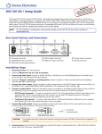
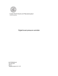
Provide the following countermeasures when using the product in an environment where the product is exposed to noise.
• Countermeasures for protecting the product against high-frequency noise or
abnormal voltages.
–
+
–
K3NV/
K3NH/
K3NR/
K3NP/
K3NC
Power input
K3NX
Intelligent
Signal
Processor
Signal input
+
Power input
Power input
Line filter
Signal input
4
Surge absorber
• Countermeasures for protecting the product against inductive noise produced
from the input line.
+
Intelligent
Signal
Processor
–
2-conductor shield wire
xiii
SECTION 1
CompoWay/F Communications Procedures
This section describes communications using the CompoWay/F format.
1-1
1-2
1-3
1-4
1-5
1-6
1-7
1-8
Introduction . . . . . . . . . . . . . . . . . . . . . . . . . . . . . . . . . . . . . . . . . . . . . . . . . . . . . . . . . . . . .
Preparation For Operation . . . . . . . . . . . . . . . . . . . . . . . . . . . . . . . . . . . . . . . . . . . . . . . . . .
1-2-1 Wiring . . . . . . . . . . . . . . . . . . . . . . . . . . . . . . . . . . . . . . . . . . . . . . . . . . . . . . . . . .
1-2-2 Communications Parameters . . . . . . . . . . . . . . . . . . . . . . . . . . . . . . . . . . . . . . . . .
Data Format . . . . . . . . . . . . . . . . . . . . . . . . . . . . . . . . . . . . . . . . . . . . . . . . . . . . . . . . . . . . .
Commands and Responses . . . . . . . . . . . . . . . . . . . . . . . . . . . . . . . . . . . . . . . . . . . . . . . . . .
1-4-1 Memory Area Read . . . . . . . . . . . . . . . . . . . . . . . . . . . . . . . . . . . . . . . . . . . . . . . .
1-4-2 Command Text Composition . . . . . . . . . . . . . . . . . . . . . . . . . . . . . . . . . . . . . . . . .
1-4-3 Memory Area Write . . . . . . . . . . . . . . . . . . . . . . . . . . . . . . . . . . . . . . . . . . . . . . . .
1-4-4 Parameter Area Read . . . . . . . . . . . . . . . . . . . . . . . . . . . . . . . . . . . . . . . . . . . . . . .
1-4-5 Parameter Area Write . . . . . . . . . . . . . . . . . . . . . . . . . . . . . . . . . . . . . . . . . . . . . .
1-4-6 Properties Read . . . . . . . . . . . . . . . . . . . . . . . . . . . . . . . . . . . . . . . . . . . . . . . . . . .
1-4-7 Controller Status Read . . . . . . . . . . . . . . . . . . . . . . . . . . . . . . . . . . . . . . . . . . . . . .
1-4-8 Internode Echo Test . . . . . . . . . . . . . . . . . . . . . . . . . . . . . . . . . . . . . . . . . . . . . . . .
1-4-9 Operating Command . . . . . . . . . . . . . . . . . . . . . . . . . . . . . . . . . . . . . . . . . . . . . . .
1-4-10 Summary of Response Codes . . . . . . . . . . . . . . . . . . . . . . . . . . . . . . . . . . . . . . . .
Memory/Parameter Area Details . . . . . . . . . . . . . . . . . . . . . . . . . . . . . . . . . . . . . . . . . . . . .
Restricting Communications Access . . . . . . . . . . . . . . . . . . . . . . . . . . . . . . . . . . . . . . . . . .
Command Lists . . . . . . . . . . . . . . . . . . . . . . . . . . . . . . . . . . . . . . . . . . . . . . . . . . . . . . . . . .
1-7-1 Read Command Lists . . . . . . . . . . . . . . . . . . . . . . . . . . . . . . . . . . . . . . . . . . . . . . .
1-7-2 Write Command Lists . . . . . . . . . . . . . . . . . . . . . . . . . . . . . . . . . . . . . . . . . . . . . .
Communications Program Example . . . . . . . . . . . . . . . . . . . . . . . . . . . . . . . . . . . . . . . . . .
2
3
3
5
5
6
6
7
8
9
11
12
13
14
15
16
17
23
24
24
28
33
1
Section
Introduction
1-1
1-1
Introduction
CompoWay/F
Communications
The program for the communications functions is created in the host computer
and the K3Nj’s parameters are monitored/set from the host computer, so the
explanation provided here is from the viewpoint of the host computer.
CompoWay/F is OMRON’s standard communications format for general serial
communications. This format uses a standard frame format as well as the FINS
commands which have proven successful in OMRON’s PCs, so it can simplify
communications between components or between personal computers and
components.
The FINS (Factory Interface Network Service) protocol provides message communications between PCs in OMRON FA networks.
Use a K3Nj with Communications Output Board, FLK1/2/3/4/5/6 for CompoWay/F communications. The K3N-series has the following communications
functions.
• Reading/Writing parameters
• Operational control
• Switching setting levels
The communications functions are limited to the following conditions.
• Parameters can be written only during remote operation.
• Only the set value can be written while in RUN mode. All other parameters are
read-only.
• Parameters cannot be written or read when a sensor error has occurred
(K3NH).
• Parameters cannot be written or read during startup lock (K3NX).
Communications
Specifications
Transmission line connection:
Communications method:
Synchronization method:
Communication speed:
Communication code:
Data bits:
Stop bits:
Error detection:
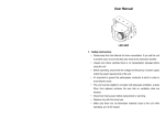
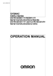
Transmission Procedure
Host computer
When the host computer transmits a command frame, the K3Nj transmits a
response frame that corresponds to the command frame. A single response
frame is returned for each command frame. The following diagram shows the
operation of the command and response frames.
Command frame
K3Nj with Communications Output Board, FLK1/2/3/4/5/6
2
Multiple point
RS-232C or RS-422 (4-wire, half-duplex)
RS-485 (2-wire, half-duplex)
Start-stop synchronization
1,200/2,400/4,800/9,600/19,200/38,400 bps
(default: 9,600 bps)
ASCII
7 or 8 bits (default: 7 bits)
(An 8-bit code is made by adding a 0 to the
7-bit code.)
1 or 2 bits (default: 2 bits)
Vertical parity (none, even, or odd)
(default: even parity)
BCC (block check character)
Start-stop synchronization data composition
Command frame
Response frame
Section
Preparation For Operation
Interface
1-2
1-2
Communications with the host computer are carried out through a standard
RS-232C, RS-422, or RS-485 interface. The model numbers indicate which
interface is incorporated in the models.
• K3Nj with Communications Output Board, FLK1/4:
RS-232C
• K3Nj with Communications Output Board, FLK2/5:
RS-422
• K3Nj with Communications Output Board, FLK3/6:
RS-485
Preparation For Operation
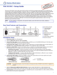
1-2-1 Wiring
RS-232C
RS-232C connections are one-to-one.
The max. cable length is 15 m. Use an RS-232C optical interface when extending the transmission line beyond 15 m.
Use a shielded, twisted-pair cable (AWG 28 or larger).
Host
computer
RS-232C
(25-pin)
Processor
RS-232C
Abbrevi- Pin
ation
No.
Pin
No.
Abbreviation
1
FG
FG
1
SG
7
SD
2
2
SD
RD
3
3
RD
RS
4
4
RS
CS
5
5
CS
DR
6
6
DR
ER
20
20
ER
MAX232C or equivalent
SG
Shielded cable
TX
RX
K3Nj-jjjj-FLK1
Host
computer
RS-232C
(9-pin)
Abbreviation
Pin
No.
Pin
No.
SG
SD
5
3
2
5
3
2
7
8
6
4
7
8
6
4
RD
RS
CS
DR
ER
Safety
shield
grounding
RS-422
Processor
RS-232C
MAX232C or equivalent
Abbreviation
SG
SD
RD
RS
CS
DR
TX
RX
ER
Shielded cable
K3Nj-jjjj-FLK4
RS-422 connections can be one-to-one or one-to-N when a 3G2A9-AL001 Link
Adapter is used. A maximum of 32 Units (including the host computer) can be
connected in one-to-N systems.
The total cable length can be 500 m max.
Use a shielded, twisted-pair cable (AWG 28 or larger).
3
Section
Preparation For Operation
1-2
Be sure to turn ON the terminator switches only in the devices at each end of the
transmission line.
Host computer
RS-422
Terminator
Processor
Abbreviation
RS-422
FG
The terminator
must have a minimum resistance of
100 Ω.
RDA
9
SDA
RDB
5
SDB
SDA
6
RSA
SDB
1
RSB
SG
3
SG
SN751177N or equivalent
Terminal
220 Ω block switch
Pin AbbreviNo. ation
6.8 V
220 Ω
Shielded cable
The terminator (220 Ω) is set with the terminal block switch.
RS-485 connections can be one-to-one or one-to-N. A maximum of 32 Units
(including the host computer) can be connected in one-to-N systems.
RS-485
The total cable length can be 500 m max.
Use a shielded, twisted-pair cable (AWG 28 or larger).
Be sure to turn ON the terminator switches only in the devices at each end of the
transmission line.
VDD
Processor
Turn OFF all terminal block
switches except at the end-station.
Host computer
RS-485
Abbreviation
RS-485
Ter- Abbreviminal ation
FG
–
19
–
+
18
+
SN751177N or equivalent
47 K
Terminal
block switch
220 Ω
4.7 K
4.7 K
SG
47 K
6.8 V
Shielded cable
Processor
end-station
RS-485
Termi- Abbrevinal ation
19
–
18
+
220 Ω
Terminal
block switch ON
Terminal block switch ON at the end station.
Shielded cable
Note SYSMAC BUS Wired Remote I/O devices cannot be connected.
Match the communications format of the K3Nj and the host computer. If a oneto-N system is being used, be sure that the communications formats of all
devices in the system (except individual Unit numbers) are the same.
This section explains how to set the K3Nj’s communication format. Refer to
your computer’s user’s manual for details on changing its communications settings.
4
Section
Data Format
1-3
1-2-2 Communications Parameters
The K3Nj’s communication format is set with the communications parameters.
These parameters are set with the K3Nj’s front panel. The following table
shows the communications parameters (option mode) and their setting ranges.
Parameter/Code
1-3
Setting range
Default setting
Unit number
uĆno
0 to 99
0
Baud rate
bps
1.2, 2.4, 4.8, 9.6, 19.2, or 38.4 (kbps)
9.6
Data bits
len
7 or 8 (bit)
7
Parity
prty
none, eUen, or odd
eUen
Stop bits
sbit
1 or 2
2
Data Format
Unless otherwise indicated, numbers in the following tables are hexadecimal.
Values in double quotation marks, such as “00,” are ASCII.
Command Frame
Sub-address
STX
Node No.
“00”
(02) (×101) | (×100)
2 bytes
2 bytes
1 byte
SID
“0”
MRC
1 byte
Command text
SRC
Data
ETX BCC
(03)
1 byte 1 byte
Response Frame
Sub-address
STX
Node No.
“00”
(02) (×101) | (×100)
2 bytes
2 bytes
1 byte
End code
“00”
2 bytes
MRC
Response text
SRC MRES SRES
Data*
ETX BCC
(03)
1 byte 1 byte
Note There will be no data if there was an error in the command frame.
(In this case, there will be an end code other than “00” or “0F.”)
STX
Node number
This code (02) indicates the beginning of the transmission
frame. Always set this character in the first byte.
This number specifies the transmission’s destination.
Specify the K3Nj’s unit number to transmit to the K3Nj.
Specify “XX” for a broadcast transmission. No responses will be
returned for broadcast transmissions.
Sub-address
Not used for the K3Nj. Always set the sub-address to “00.”
SID (Service ID)
Not used for the K3Nj. Always set the SID to “0.”
End code
Indicates the execution result for the corresponding command
frame.
This is the main component of the command. Refer to 1-4-2
Command Text Composition for details.
Indicate the service being used. Refer to 1-4-2 Command Text
Composition for details.
Indicate the transmission results.
Command text
MRC, SRC
(Command code)
MRES, SRES
(Response code)
ETX
BCC
This code (03) indicates the end of the text.
Block Check Character
• This is the BCC result for the data from just after STX until ETX.
• Horizontal parity (1 character display)
The BCC result is found by calculating the exclusive OR of the bytes from just
after STX until ETX.
5
Section
Commands and Responses
1-4
End Code Summary
End code
1-4
Name
Meaning
“00”
Normal completion
The command was completed normally, without
any of the following errors.
The specified command couldn’t be executed.
The response code should indicate why the
command couldn’t be executed.
“0F”
Command error
“10”
Parity error
“11”
Framing error
“12”
Overrun error
“13”
BCC error
“14”
Format error
The command text was incorrect. This error will
occur when a character other than “0” to “9” or
“A” to “F” is included in the command text.
“16”
Sub-address error
“18”
Frame length error
The received frame’s header or address is
incorrect.
The received frame exceeded the prescribed
number of bytes.
A parity error occurred in one of the characters
during reception.
A framing error occurred in one of the
characters during reception.
An overrun error occurred in one of the
characters during reception.
The received frame’s BCC was incorrect.
Commands and Responses
1-4-1 Memory Area Read
Command Text within the Command Frame
MRC
“01”
2 bytes
SRC
“01”
2 bytes
1, 2, 3...
Memory
type
“C0”
2 bytes
Starting read address
See section 1-5.
4 bytes
“00”
Number of elements
“0001”
4 bytes
1. Memory type
Memory type
“C0”
Meaning
Present value (PV), MAX value, MIN value, status, or set
value
2. Starting read address
Specify the address of the data which you want to read in 4-digit hexadecimal. Refer to 1-5 Memory/Parameter Area Details for details on the starting
addresses of each memory type.
3. Number of elements (4-digit hexadecimal)
Number of
elements
“0001”
Process
Executes the read operation and completes it normally.
Note If “0000” is specified, the read operation won’t be executed but the
command will be completed normally. Any value other than “0000” or
“0001” will cause a parameter error.
6
Section
Commands and Responses
1-4
Response Text within the Response Frame
SRC
“01”
2 bytes
MRC
“01”
2 bytes
Response code
Read data
4 bytes
1, 2, 3...
8 bytes
1. Response code
Response code
Meaning
“0000”
Normal completion
“1001”
Command too long
“1002”
Command too short
“1100”
Parameter error
“1101”
Area type error
“1103”
Starting address out-of-range error
“2203”
Operating error
2. Read data
The specified data is transferred in 8-digit hexadecimal. Only the status data
is bit information. (Refer to 1-5 Memory/Parameter Area Details for details
on the data.)
1-4-2 Command Text Composition
Valid Command Codes
Command
Action
Comments
MRC SRC
“01” “01” Memory area read
Reads or writes the present value (PV),
maximum value,
value minimum value,
value status,
status or
set value.
“01”
“02”
Memory area write
“02”
“02”
“05”
“01”
“02”
“03”
Parameter area read
Parameter area write
Properties read
“06”
“01”
Controller status read
“08”
“01”
Internode echo test
“30”
“05”
Operating command
Reads or writes settings
g other than p
present
values.
l
Reads information such as model number
and buffer size, which the host computer
uses to verify the upper limit of the data
length.
Reads operational status information.
Returns data sent from the host computer
unchanged.
Executes hold, reset, forced-zero,
max./min. value reset, remote/local
selection, or mode selection.
Command Frame Composition
STX
(02)
Node No.
(×101)
Sub-address
SID
“00”
“0”
(×100)
MRC
Command
ETX
Command text
SRC
BCC
(03)
Data
Code
Data
Page
Memory area read
“01”
“01”
Memory type
Address
“00”
Number of elements
---
6
Memory area write
“01”
“02”
Memory type
Address
“00”
Number of elements
Write data
8
Parameter area read
“02”
“01”
Parameter type
Address
Number of elements
---
9
Parameter area write
“02”
“02”
Address
Number of elements
Write data
11
Properties read
Controller status read
Internode echo test
“05”
“06”
“08”
“03”
“01”
“01”
Parameter type
---
Operating command
“30”
“05”
Test data
12
13
14
Command code
15
7
Section
Commands and Responses
1-4
1-4-3 Memory Area Write
Text within the Command Frame
MRC
“01”
2 bytes
SRC
“02”
2 bytes
Memory
type
“C0”
2 bytes
Starting read address
See section 1-5.
4 bytes
“00”
Number of elements
“0001”
4 bytes
Write data
Refer to 1-5 Memory/Parameter Area Details
8 bytes
1, 2, 3...
1. Memory type
Memory type
“C0”
Meaning
Set value
2. Starting write address
Specify (in 4-digit hexadecimal) the address of the data which you want to
write. Refer to 1-5 Memory/Parameter Area Details for details on the starting
addresses of each memory type.
3. Number of elements (4-digit hexadecimal)
Number of
elements
“0001”
Process
Executes the write operation and completes it normally.
Note If “0000” is specified, the write operation won’t be executed but the
command will be completed normally. Any value other than “0000” or
“0001” will cause a parameter error.
4. Write data
Specify the data which you want to write. Refer to 1-5 Memory/Parameter
Area Details for details on the write data.
Response Text within the Response Frame
MRC
“01”
2 bytes
SRC
“02”
2 bytes
Response code
4 bytes
Response codes
Response code
Meaning
“0000”
Normal completion
“1001”
Command too long
“1002”
Command too short
“1100”
Parameter error
“1101”
Area type error
“1103”
Starting address out-of-range error
“2203”
Operating error
“3003”
Read-only data
Note The write operation won’t be executed unless the response code is “0000.”
8
Section
Commands and Responses
1-4
1-4-4 Parameter Area Read
Text within the Command Frame
MRC
“02”
2 bytes
1, 2, 3...
SRC
“01”
2 bytes
Parameter
type
See 1.
2 bytes
Starting read address
See section 1-5.
4 bytes
Number of elements
“8001”
4 bytes
1. Parameter type
K3NH
Type
“8000”
“C00C”
“8824”
Meaning
Input type, decimal point position (see note), average processing,
hysteresis, and comparative output pattern
Scaling upper limit value, scaling lower limit value, upper-limit
compensation value, and Lower-limit compensation value
Temperature unit, standby sequence, and display digit change
Note An error response will be returned if a temperature input (inĆt) has
been selected for the input type.
K3NX
Type
“8000”
“C00C”
“8824”
Meaning
Input range, decimal point position, average processing, startup
compensation time, hysteresis, and comparative output pattern
Scaling input value 2, scaling display value 2, scaling input value 1,
and scaling display value 1
Power supply frequency
K3NV
Type
“8000”
“C00C”
“8824”
Meaning
Input range, decimal point position, average processing, startup
compensation time, hysteresis, and comparative output pattern
Scaling input value 2, scaling display value 2, scaling input value 1,
and scaling display value 1
Power supply frequency
K3NR
Type
Meaning
“8000”
Operating mode, decimal point position, process time for averaging
measured value, startup compensation time, hysteresis, and
comparative output pattern
“C00C”
Prescaling value X (mantissa) of input A, prescaling value Y
(exponent) of input A, prescaling value X (mantissa) of input B, and
prescaling value Y (exponent) of input B
“8824”
Sensor type, time unit, power failure memory
“C82A”
Auto zero time of input A X (mantissa), auto zero time of input A Y
(exponent), auto zero time of input B Y (mantissa), and auto zero
time of input B Y (exponent)
K3NP
Type
“8000”
“C00C”
“8824”
Meaning
Operating mode, decimal point position, and comparative output
pattern
Prescaling value X (mantissa) of input A and prescaling value Y
(exponent) of input A
Sensor type and time unit
9
Section
Commands and Responses
1-4
K3NC
Type
Meaning
“8000”
“C00C”
“8824”
“C82A”
Operating format, decimal point position, and comparative output
pattern
Prescaling value X (mantissa) of input A and prescaling value Y
(exponent) of input A
Sensor type, power failure memory, and compensation input
condition
Compensation value
2. Starting read address
Specify (in 4-digit hexadecimal) the address of the data which you want to
read. Refer to 1-5 Memory/Parameter Area Details for details on the starting
addresses of each parameter type.
3. Number of elements
Number of
elements
“8001”
Process
Executes the read operation and completes it normally.
Note If “8000” is specified, the read operation won’t be executed but the
command will be completed normally. Any value other than “8000” or
“8001” will cause a parameter error.
Response Text within the Response Frame
MRC
“02”
2 bytes
SRC
“01”
2 bytes
Response code
Parameter type
Starting read address
Number of elements
4 bytes
4 bytes
4 bytes
4 bytes
Read data
8 bytes max.
1, 2, 3...
1. Response codes
Response code
Meaning
“0000”
Normal completion
“1001”
Command too long
“1002”
Command too short
“1100”
Parameter error
“1101”
Area type error
“1103”
Starting address out-of-range error
“2203”
Operating error
2. Parameter type and starting read address
The parameter type and starting read address specified in the command will
be returned.
3. Read data
The data specified in the command will be returned.
4. Number of elements
The number of elements specified in the command will be returned.
10
Section
Commands and Responses
1-4
1-4-5 Parameter Area Write
Text within the Command Frame
MRC
“02”
2 bytes
SRC
“02”
2 bytes
Parameter type
See 1., below.
4 bytes
Starting write address
See section 1-5.
4 bytes
Number of elements
“8001”
4 bytes
Write data
Refer to 1-5 Memory/Parameter Area Details
8 bytes max.
1, 2, 3...
1. Parameter type
K3NH
Type
“8000”
“C00C”
“8824”
Meaning
Input type, decimal point position, average processing, hysteresis,
and comparative output pattern
Scaling upper limit value, scaling lower limit value, upper-limit
compensation value, and lower-limit compensation value
Temperature unit, standby sequence, and display digit change
K3NX
Type
“8000”
“C00C”
“8824”
Meaning
Input range, decimal point position, average processing, startup
compensation time, hysteresis, and comparative output pattern
Scaling input value 2, scaling display value 2, scaling input value 1,
and scaling display value 1
Power supply frequency
K3NV
Type
“8000”
“C00C”
“8824”
Meaning
Input range, decimal point position, average processing, startup
compensation time, hysteresis, and comparative output pattern
Scaling input value 2, scaling display value 2, scaling input value 1,
and scaling display value 1
Power supply frequency
K3NR
Type
Meaning
“8000”
Operating mode, decimal point position, process time for averaging
measured value, startup compensation time, hysteresis, and
comparative output pattern
“C00C”
Prescaling value X (mantissa) of input A, prescaling value Y
(exponent) of input A, prescaling value X (mantissa) of input B, and
prescaling value Y (exponent) of input B
“8824”
Sensor type, time unit, power failure memory
“C82A”
Auto zero time of input A X (mantissa), auto zero time of input A Y
(exponent), auto zero time of input B Y (mantissa), and auto zero
time of input B Y (exponent)
K3NP
Type
“8000”
“C00C”
“8824”
Meaning
Operating mode, decimal point position, and comparative output
pattern
Prescaling value X (mantissa) of input A and prescaling value Y
(exponent) of input A
Sensor type and time unit
11
Section
Commands and Responses
1-4
K3NC
Type
“8000”
“C00C”
“8824”
“C82A”
Meaning
Operating format, decimal point position, and comparative output
pattern
Prescaling value X (mantissa) of input A and prescaling value Y
(exponent) of input A
Sensor type, power failure memory, and compensation input
condition
Compensation value
2. Starting write address
Specify (in 4-digit hexadecimal) the address of the data which you want to
write. Refer to 1-5 Memory/Parameter Area Details for details on the starting
addresses of each parameter type.
3. Number of elements (4-digit hexadecimal)
Number of
elements
“8001”
Process
Executes the write operation and completes it normally.
Note If “8000” is specified, the write operation won’t be executed but the
command will be completed normally. Any value other than “8000” or
“8001” will cause a parameter error.
4. Write data
Specify the data which you want to write. Refer to 1-5 Memory/Parameter
Area Details for details on the write data.
Response Text within the Response Frame
MRC
“02”
2 bytes
SRC
“02”
2 bytes
Response code
4 bytes
Response codes
Response code
Meaning
“0000”
Normal completion
“1001”
Command too long
“1002”
Command too short
“1100”
Parameter error
“1101”
Area type error
“1103”
Starting address out-of-range error
“2203”
Operating error
Note The write operation won’t be executed unless the response code is “0000.”
1-4-6 Properties Read
Text within the Command Frame
MRC
“05”
2 bytes
SRC
“03”
2 bytes
Response Text within the Response Frame
MRC
“05”
2 bytes
12
SRC
“03”
2 bytes
Response code
Model number
Buffer size
4 bytes
10 bytes
4 bytes
Section
Commands and Responses
1, 2, 3...
1-4
1. Response codes
Response code
Meaning
“0000”
Normal completion
“1001”
Command too long
“2203”
Operating error
2. Model number
The 10-byte ASCII model number will be returned as is (from the left). The
overall format is “K3N --.”
:
This is the fourth character in the model number (H, R, P, C, X, or V).
: These characters indicate the input specifications, as shown below.
Characters Meaning
TA
K3NH
NB
NPN input for the K3NR, K3NP, or K3NC
PB
PNP input for the K3NR, K3NP, or K3NC
VD
K3NX (DC voltage input)
AD
K3NX (DC current input)
VA
K3NX (AC voltage input)
AA
K3NX (AC current input)
LC
K3NV
:
This is the Output Unit’s code.
Number
Code
Meaning
1
FLK1
Communications (RS-232C)
2
FLK2
Communications (RS-485)
3
FLK3
Communications (RS-422)
4
FLK4
5
FLK5
6
FLK6
Communications + Transistor output
(RS-232C + NPN open collector)
Communications + Transistor output
(RS-485 + NPN open collector)
Communications + Transistor output
(RS-422 + NPN open collector)
3. Communications buffer size
Indicates the size of the communications buffer in 4-digit hexadecimal. The
hexadecimal number is represented in ASCII and is always “0025” (37
bytes).
1-4-7 Controller Status Read
Text within the Command Frame
MRC
“06”
2 bytes
SRC
“01”
2 bytes
Response Text within the Response Frame
MRC
“06”
2 bytes
1, 2, 3...
SRC
“01”
2 bytes
Response code
RUN status
Related
information
4 bytes
4 bytes
4 bytes
1. Response codes
Response code
Meaning
“0000”
Normal completion
“1001”
Command too long
“2203”
Operating error
13
Section
Commands and Responses
1-4
2. RUN status
“00”
Operating in RUN mode
“01”
Operating in setting mode
“02”
Performing output test
3. Related information
The related information (binary) is returned as 2-digit ASCII code.
Bank No.
(see note)
HOLD status
RESET status
Forced-zero status
LL comparative output (OUT1)
L comparative output (OUT2)
H comparative output (OUT4)
HH comparative output (OUT5)
PASS output (OUT3)
Local/remote status (0: local, 1: remote)
A “0” will be returned for a function if the Unit isn’t equipped with that function.
The output numbers in parentheses are for the K3NC.
Note Refer to the following table for the bank number that has been set. These are
valid only for the K3NR, K3NP, and K3NC.
22
Bank No.
21
20
Bank 0
OFF
OFF
OFF
Bank 1
OFF
OFF
ON
Bank 2
OFF
ON
OFF
Bank 3
OFF
ON
ON
Bank 4
OFF
OFF
OFF
1-4-8 Internode Echo Test
Text within the Command Frame
SRC
“01”
2 bytes
MRC
“08”
2 bytes
Test data
20 bytes max.
The test data can be any arbitrary data (1 to 20 bytes), although the bytes of data
must be within the following ranges:
20 to FF hexadecimal when the number of data bits is set to 8.
20 to 7F hexadecimal when the number of data bits is set to 7.
Note The test data isn’t checked for out-of range values.
Response Text within the Response Frame
MRC
“08”
2 bytes
14
SRC
“01”
2 bytes
Response code
4 bytes
Test data
20 bytes max.
Section
Commands and Responses
1, 2, 3...
1-4
1. Response codes
Response code
Meaning
“0000”
Normal completion
“1001”
Command too long
“2203”
Operating error
2. Test data
The test data sent by the command is returned unchanged.
1-4-9 Operating Command
Text within the Command Frame
MRC
“30”
2 bytes
SRC
“05”
2 bytes
Command
code
Sub-code
2 bytes
2 bytes
The following table shows the four command codes and the sub-codes for
commands that require them.
Code
“10”
“11”
Command
Reset maximum and
minimum values.
Forced-zero
Sub-code
None
“00”: Clear forced-zero setting. “01”: Execute
(Invalid for the K3NR, K3NP, K3NC, and K3NH.)
“12”
“13”
Remote/local
programming
Switch mode.
“00”: Local
“01”: Remote
“00”: RUN mode
“01”: Setting mode
Response Text within the Response Frame
MRC
“30”
2 bytes
1, 2, 3...
SRC
“05”
2 bytes
Response code
4 bytes
Command
code
2 bytes
1. Response code
Response code
Meaning
“0000”
Normal completion
“1001”
Command too long
“1002”
Command too short
“1100”
Parameter error
“2203”
Operating error
2. Command code
The command code sent by the command is returned unchanged when the
command was completed normally or an operating error occurred.
15
Section
Commands and Responses
1-4
1-4-10 Summary of Response Codes
Response
code
“0000“
Normal completion
The command was completed properly.
“0401”
Undefined command
The command was incorrect.
“1002”
Command too short
Some required data was missing from the command.
“1003”
Number of elements/Data
mismatch
An error occurred while writing data.
“1100”
Parameter error
The specified parameters(s) were incorrect.
“1101”
Area type error
The area type (memory/parameter) specification was incorrect.
“1103”
The specified starting address was outside of the allowed range.
“110B”
Starting address out-of-range
error
End address out-of range
error
Response too long
“2203”
Operating error
Attempted to change a set value while in local mode.
“1104”
Name
Meaning
The specified number of elements and amount of data didn’t agree.
The specified end address (starting address + number of elements) was
outside of the allowed range.
The response exceeded the maximum response length (37 bytes).
Attempted to change a setting other than a set value while in RUN
mode.
Execution wasn’t possible because the startup compensation time
function was being executed. (K3NX)
“3003”
16
Read-only data
Couldn’t write data because the specified area is read-only.
Section
Memory/Parameter Area Details
1-5
1-5
Memory/Parameter Area Details
Memory: K3NH, K3NX, K3NV, K3NR, and K3NP
Type
“C0”
Address
Data contents
“0000“
“0001”
“0002”
“0003”
Present value (PV)
Maximum value
Minimum value
Status data:
“F0019999” to “00099999” (See note 1.)
“F0019999” to “00099999” (See note 1.)
“F0019999” to “00099999” (See note 1.)
Bit 0:
Present value overflow
Bit 1:
Present value underflow
Bit 2:
Maximum value overflow
Bit 3:
Maximum value underflow
Bit 4:
Minimum value overflow
Bit 5:
Minimum value underflow
Bit 6:
Present value sensor error (K3NH only)
Bit 7:
Maximum value sensor error (K3NH only)
Bit 8:
Minimum value sensor error (K3NH only)
Others: The remaining bits are always 0.
“X004”
“X005”
“X006”
“X007”
HH set value
H set value
L set value
LL set value
“F0019999” to “00099999” (See note 1.)
“F0019999” to “00099999” (See note 1.)
“F0019999” to “00099999” (See note 1.)
“F0019999” to “00099999” (See note 1.)
Note
Data length
Double words
1. In the K3NH, the range is “F0001999” to “00009999” when the display digit
change is set to 4 digits.
2. The leading “X” in the addresses represents the bank number in the K3NR
and K3NP. (This digit is always 0 in the other models.)
3. Data values which begin with an “F” are negative values.
4. The following diagram shows the details of the status bits:
Always 0
Status data
(3 hexadecimal digits represented by ASCII characters.)
Present value overflow
Present value underflow
Maximum value overflow
Maximum value underflow
Minimum value overflow
Minimum value underflow
Present value sensor error (K3NH only)
Maximum value sensor error (K3NH only)
Minimum value sensor error (K3NH only)
Always 0
17
Section
Memory/Parameter Area Details
1-5
Memory: K3NC
Type
“C0”
Address
Data contents
“0000“
“0003”
Present value (PV)
Status data:
“F0019999” to “00099999”
Bit 0:
Present value overflow
Bit 1:
Present value underflow
Others: The remaining bits are always 0.
“X004”
“X005”
“X006”
“X007”
“X008”
OUT1 set value
OUT2 set value
OUT3 set value
OUT4 set value
OUT5 set value
“F0019999” to “00099999”
“F0019999” to “00099999”
“F0019999” to “00099999”
“F0019999” to “00099999”
“F0019999” to “00099999”
Note
Always 0
1. The leading “X” in the addresses represents the bank number.
2. Data values which begin with an “F” are negative values.
3. The following diagram shows the details of the status bits:
Status data
(2 hexadecimal digits represented by ASCII characters.)
Present value overflow
Present value underflow
Always 0
18
Data length
Double words
Section
Memory/Parameter Area Details
1-5
Parameters: K3NH
Type
“8000”
Address
“0000”
“0001”
“0002”
Data contents
Input type
Decimal point position
Average processing
“0000” to “0021”
“0000” to “0003” (See note 1.)
Data length
Words
“0000”
No averaging
“0001” to “0004” Moving average: 2, 4, 8, or 16 times
“0011” to “0014” Simple average: 2, 4, 8, or 16 times
“0003”
“0004”
“0005”
Not used.
Hysteresis
“0001” to “9999”
Comparative output pattern
“0000”
“0001”
“0002”
“C00C”
“0000”
“0001”
“0002”
Standard output
Zone output
Level output
Scaling upper limit value “F0019999” to “00099999”
Scaling lower limit value “F0019999” to “00099999”
Upper-limit compensation value
Double words
“F0019999” to “00099999”
“8824”
“0003”
Lower-limit compensation value
“0000”
“F0019999” to “00099999”
Temperature unit
“0000”
“0001”
_C (Celsius)
_F (Fahrenheit)
“0001”
Standby sequence
“0002”
“0000” OFF
“0001” ON
Display digit change
“0000”
“0001”
Note
Words
4 digits
5 digits
1. An error response will be returned if a temperature input (inĆt) has been
selected for the input type.
2. Data values which begin with an “F” are negative values.
19
Section
Memory/Parameter Area Details
1-5
Parameters: K3NX
Type
“8000”
Address
“0000”
“0001”
“0002”
Data contents
Input range
Decimal point position
Average processing
“0000” to “0004”
“0000” to “0004”
Data length
Words
“0000”
No averaging
“0001” to “0005” Moving average: 2, 4, 8, 16, or 32 times
“0011” to “0015” Simple average: 2, 4, 8, 16, or 32 times
“0003”
Startup compensation time
“0000” to “0999”
“0004”
“0005”
Hysteresis
“0001” to “9999”
Comparative output pattern
“0000”
“0001”
“0002”
“C00C”
“8824”
“0000”
“0001”
“0002”
“0003”
“0000”
Standard output
Zone output
Level output
Scaling input value 2
Scaling display value 2
Scaling input value 1
Scaling display value 1
Power supply frequency
“0000”
“0001”
“F0019999” to “00099999”
“F0019999” to “00099999”
“F0019999” to “00099999”
“F0019999” to “00099999”
Double words
Words
50 Hz
60 Hz
Note Data values which begin with an “F” are negative values.
Parameters: K3NV
Type
“8000”
Address
“0000”
“0001”
“0002”
Data contents
Input range
Decimal point position
Average processing
“0000” to “0002”
“0000” to “0004”
Data length
Words
“0000”
No averaging
“0001” to “0005” Moving average: 2, 4, 8, 16, or 32 times
“0011” to “0015” Simple average: 2, 4, 8, 16, or 32 times
“0003”
Startup compensation time
“0004”
“0005”
“0000” to “0999”
Hysteresis
“0001” to “9999”
Comparative output pattern
“0000”
“0001”
“0002”
“C00C”
“8824”
“0000”
“0001”
“0002”
“0003”
“0000”
Standard output
Zone output
Level output
Scaling input value 2
Scaling display value 2
Scaling input value 1
Scaling display value 1
Power supply frequency
“0000”
“0001”
“F0019999” to “00099999”
“F0019999” to “00099999”
“F0019999” to “00099999”
“F0019999” to “00099999”
50 Hz
60 Hz
Note Data values which begin with an “F” are negative values.
20
Double words
Words
Section
Memory/Parameter Area Details
1-5
Parameters: K3NR
Type
“8000”
Address1
“0000”
“X001”
“0002”
“0003”
“0004”
“0005”
Data contents
Operating mode
Decimal point position
Process time for averaging measured value
Startup compensation time
Hysteresis
Comparative output pattern
“0000”
“0001”
“0002”
“C00C”
“8824”
“X000”
“X001”
“X002”
“X003”
“0000”
“0001”
“C82A”
Standard output
Zone output
Level output
Prescaling value X (mantissa) of input A
Prescaling value Y (exponent) of input A
Prescaling value X (mantissa) of input B
Prescaling value Y (exponent) of input B
Sensor type
“0000” to “1111” (binary)
Time unit
“0000”
“0001”
“0002”
“0003”
“0004”
“00000001” to “00099999”
“F0000009” to “00000009”
“00000001” to “00099999”
“F0000009” to “00000009”
Double words
Words
Prescaling value
Seconds
Minutes
Hours, minutes, and seconds
Minutes and seconds
“0002”
Power failure memory
“0000”
“0001”
“0002”
“0003”
“0000” Disabled
“0001” Enabled
Auto zero time of input A X (mantissa)
Auto zero time of input A Y (exponent)
Auto zero time of input B Y (mantissa)
Auto zero time of input B Y (exponent)
Note
“0000” to “0006”
“0000” to “0004”
“0000” to “0006”
“0001” to “0999”
“0001” to “9999”
Data length
Words
“00000001” to “00099999”
“F0000009” to “00000009”
“00000001” to “00099999”
“F0000009” to “00000009”
Double words
1. The leading “X” in the addresses represents the bank number.
2. Data values which begin with an “F” are negative values.
21
Section
Memory/Parameter Area Details
1-5
Parameters: K3NP
Type
“8000”
Address1
“0000”
“X001”
“0002”
“0003”
“0004”
“0005”
Data contents
Data length
Words
Operating mode
“0000” to “0005”
Decimal point position
“0000” to “0004”
Not used.
Not used.
Not used.
Comparative output pattern
“0000”
“0001”
“0002”
Standard output
Zone output
Level output
“C00C”
“X000”
“X001”
Prescaling value X (mantissa) of input A
Prescaling value Y (exponent) of input A
“8824”
“0000”
“0001”
Sensor type
Time unit
“0000”
“0001”
“0002”
“0003”
“0004”
Note
“00000001” to “00099999”
“F0000009” to “00000009”
Double words
Words
“0000” to “1111” (binary)
Prescaling value
Seconds
Minutes
Hours, minutes, and seconds
Minutes and seconds
1. The leading “X” in the addresses represents the bank number.
2. Data values which begin with an “F” are negative values.
Parameters: K3NC
Type
“8000”
Address1
“0000”
“X001”
“0002”
“0003”
“0004”
“0005”
Data contents
Input mode
Decimal point position
Not used.
Not used.
Not used.
Output mode
“0000”
“0001”
ALL-H
ALL-L
“X000”
“X001”
Prescaling value X (mantissa) of input A
Prescaling value Y (exponent) of input A
“8824”
“0000”
“0001”
Sensor type
“0000” to “1111” (binary)
Power failure memory
“0002”
“0000” Disabled
“0001” Enabled
Compensation input condition
“C82A”
“0000”
“00000001” to “00099999”
“F0000009” to “00000009”
“F0019999” to “00099999”
Words
Double words
1. The leading “X” in the addresses represents the bank number.
2. Data values which begin with an “F” are negative values.
22
Double words
Unconditional
Only when adding
Compensation value
Note
Words
“0001” or “0002”
“0000” to “0004”
“C00C”
“0000”
“0001”
Data length
Restricting Communications Access
1-6
Section
1-6
Restricting Communications Access
Control of the Unit through the communications interface can be restricted in two
ways:
• Restricting Access with Protect Settings
The protect mode’s security setting can be used to write-protect the set values.
The write-protected set values can be read through the communications interface, but not changed.
• Restricting Access with the Remote/Local Processing Setting
The remote/local processing setting determines whether set values can be
overwritten by key operations or through the communications interface.
Change the mode setting as necessary to enable settings to be changed
locally or remotely. The remote/local processing setting can be changed
through the communications interface or by key operations (in the option
menu).
1, 2, 3...
1. Restrictions in remote processing
In remote processing, settings cannot be changed with key operations. Only
the remote/local switch (operating command) is valid.
If you attempt to change a displayed setting in remote processing with the
keys, a message will appear indicating that the Unit is in remote processing
and the display will revert to the previous set value display.
All settings which aren’t write-protected can be changed through the communications interface when the Unit is in settings mode. Only set values can
be changed while the Unit is in RUN mode. Changes to settings are reflected
in the display immediately.
2. Restrictions in local processing
In local processing, settings cannot be changed through the communications interface (data-write commands).
If you attempt to change a setting in local processing with a data-write command, a mode error response will be returned and the setting will not be
overwritten. There are no restrictions on the data-read commands.
23
Section
Command Lists
1-7
1-7
Command Lists
1-7-1 Read Command Lists
K3NX
Command
Present value read
Maximum value read
Minimum value read
Status read
HH set value read
H set value read
L set value read
LL set value read
Input type
Decimal point position
Average processing
Startup compensation time
Hysteresis
Comparative output pattern
Scaling input value 2
Scaling display value 2
Scaling input value 1
Scaling display value 1
Power supply frequency
K3NH
24
Code
“0101”
“0201”
Command
Code
Present value read
Maximum value read
Minimum value read
Status read
HH set value read
H set value read
L set value read
LL set value read
Input type
Decimal point position
Average processing
Hysteresis
Comparative output pattern
Scaling upper limit value
Scaling lower limit value
Upper-limit compensation value
Lower-limit compensation value
Temperature unit
Standby sequence
Display digit change
“0101”
“0201”
Type
Starting
read
address
“C0”
“0000”
“0001”
“0002”
“0003”
“0004”
“0005”
“0006”
“0007”
“8000” “0000”
“0001”
“0002”
“0003”
“0004”
“0005”
“C00C” “0000”
“0001”
“0002”
“0003”
“8824” “0000”
Type
“C0”
Starting
read
address
“0000”
“0001”
“0002”
“0003”
“0004”
“0005”
“0006”
“0007”
“8000” “0000”
“0001”
“0002”
“0004”
“0005”
“C00C” “0000”
“0001”
“0002”
“0003”
“8824” “0000”
“0001”
“0002”
Filler
“00”
Number
of
elements
“0001”
“8001”
Filler
“00”
Number
of
elements
“0001”
“8001”
Section
Command Lists
K3NR
Command
Code
“0101”
Present value read
Maximum value read
Minimum value read
Status read
HH set value read
H set value read
L set value read
LL set value read
“0201”
Operating mode
Decimal point position
Process time for averaging
measured value
Startup compensation time
Hysteresis
Comparative output pattern
Prescaling value X (mantissa) of
input A
Prescaling value Y (exponent)
of input A
Prescaling value X (mantissa) of
input B
Prescaling value Y (exponent)
of input B
Sensor type
Time unit
Power failure memory
Auto zero time of input A X
(mantissa)
Auto zero time of input A Y
(exponent)
Auto zero time of input B Y
(mantissa)
Auto zero time of input B Y
(exponent)
Type
“C0”
“8000”
Starting
read
address
Filler
“0000”
“0001”
“0002”
“0003”
“X004”
“X005”
“X006”
“X007”
“0000”
“0001”
“0002”
“00”
1-7
Number
of
elements
“0001”
“8001”
“0003”
“0004”
“0005”
“C00C” “X000”
“X001”
“X002”
“X003”
“8824”
“0000”
“0001”
“0002”
“C82A” “0000”
“0001”
“0002”
“0003”
25
Section
Command Lists
K3NP
Command
Code
“0101”
Present value read
Maximum value read
Minimum value read
Status read
HH set value read
H set value read
L set value read
LL set value read
“0201”
Operating mode
Decimal point position
Comparative output pattern
Prescaling value X (mantissa) of
input A
Prescaling value Y (exponent)
of input A
Sensor type
Time unit
K3NC
Command
Code
“0101”
Present value read
Status read
OUT1 set value read
OUT2 set value read
OUT3 set value read
OUT4 set value read
OUT5 set value read
“0201”
Input mode
Decimal point position
Output mode
Prescaling value X (mantissa) of
input A
Prescaling value Y (exponent)
of input A
Sensor type
Power failure memory
Compensation input condition
Compensation value
26
Type
Starting
read
address
“C0”
“0000”
“0001”
“0002”
“0003”
“X004”
“X005”
“X006”
“X007”
“8000” “0000”
“0001”
“0005”
“C00C” “X000”
Filler
“00”
1-7
Number
of
elements
“0001”
“8001”
“X001”
“8824”
Type
“0000”
“0001”
Starting
read
address
“C0”
“0000”
“0003”
“X004”
“X005”
“X006”
“X007”
“X008”
“8000” “0000”
“0001”
“0005”
“C00C” “X000”
“X001”
“8824”
“0000”
“0001”
“0002”
“C82A” “0000”
Filler
Number
of
elements
“00”
“0001”
“8001”
Section
Command Lists
K3NV
Command
Present value read
Maximum value read
Minimum value read
Status read
HH set value read
H set value read
L set value read
LL set value read
Input type
Decimal point position
Average processing
Startup compensation time
Hysteresis
Comparative output pattern
Scaling input value 2
Scaling display value 2
Scaling input value 1
Scaling display value 1
Power supply frequency
Code
“0101”
“0201”
Type
“C0”
Starting
read
address
“0000”
“0001”
“0002”
“0003”
“X004”
“X005”
“X006”
“X007”
“8000” “0000”
“0001”
“0002”
“0003”
“0004”
“0005”
“C00C” “0000”
“0001”
“0002”
“0003”
“8824” “0000”
Filler
“00”
1-7
Number
of
elements
“0001”
“8001”
27
Section
Command Lists
1-7
1-7-2 Write Command Lists
K3NX
Command
HH set value write
H set value write
L set value write
LL set value write
Input range
Code
Type
“0102”
“C0”
“0202”
“8000”
Starting
write
address
Filler
“0004”
“0005”
“0006”
“0007”
“0000”
“00”
Decimal point position
“0001”
Average processing
“0002”
Startup compensation time
Hysteresis
Comparative output pattern
“0003”
“0004”
“0005”
Scaling input value 2
Scaling display value 2
Scaling input value 1
Scaling display value 1
Power supply frequency
28
“C00C” “0000”
“0001”
“0002”
“0003”
“8824” “0000”
Number
of
elements
“0001”
“8001”
Write data
“F0019999” to “00099999”
“0000”:
“0001”:
“0002”:
“0003”:
“0004”:
A
B
C
D
E
“0000”: jjjjj
“0001”: jjjj.j
“0002”: jjj.jj
“0003”: jj.jjj
“0004”: j.jjjj
“0000”: No averaging
“0001”: Moving average, 2 times
“0002”: Moving average, 4 times
“0003”: Moving average, 8 times
“0004”: Moving average, 16 times
“0005”: Moving average, 32 times
“0011”: Simple average, 2 times
“0012”: Simple average, 4 times
“0013”: Simple average, 8 times
“0014”: Simple average, 16 times
“0015”: Simple average, 32 times
“0000” to “0999” (0.1 s units)
“0001” to “9999”
“0000”: Standard output
“0001”: Zone output
“0002”: Level output
“F0019999” to “00099999”
“F0019999” to “00099999”
“F0019999” to “00099999”
“F0019999” to “00099999”
“0000”: 50 Hz
“0001”: 60 Hz
Section
Command Lists
1-7
K3NH
Command
Code
Type
Starting
write
address
Filler
Number
of
elements
“00”
“0001”
“F0019999” to “00099999”
“8001”
“0000”:
“0001”:
“0002”:
“0003”:
“0004”:
“0005”:
“0006”:
“0007”:
“0008”:
“0009”:
“0010”:
“0011”:
“0012”:
“0013”:
“0014”:
“0015”:
“0016”:
“0017”:
“0018”:
“0019”:
“0020”:
“0021”:
Jpt100
Pt100
K1
K2
J1
J2
T
E
L1
L2
U
N
R
S
B
W
PLII
4 to 20 mA
0 to 20 mA
1 to 5 V
0 to 5 V
1 to 10 V
jjjj
jjj.j
jj.jj
j.jjj
HH set value write
H set value write
L set value write
LL set value write
“0102”
“C0”
“0004”
“0005”
“0006”
“0007”
Input type
“0202”
“8000”
“0000”
Write data
Decimal point position
“0001”
“0000”:
“0001”:
“0002”:
“0003”:
Average processing
“0002”
Hysteresis
Comparative output pattern
“0004”
“0005”
“0000”: No averaging
“0001”: Moving average, 2 times
“0002”: Moving average, 4 times
“0003”: Moving average, 8 times
“0004”: Moving average, 16 times
“0011”: Simple average, 2 times
“0012”: Simple average, 4 times
“0013”: Simple average, 8 times
“0014”: Simple average, 16 times
“0001” to “9999”
“0000”: Standard output
“0001”: Zone output
“0002”: Level output
Scaling upper limit value
Scaling lower limit value
Upper-limit compensation
value
Lower-limit compensation
value
Temperature unit
“C00C” “0000”
“0001”
“0002”
“–1999” to “9999”
“–1999” to “9999”
“–1999” to “9999”
“0003”
“–1999” to “9999”
“0000”
“0000”:
“0001”:
“0000”:
“0001”:
“0”:
“1”:
“8824”
Standby sequence
“0001”
Display digit change
“0002”
°C
°F
OFF
ON
4 digits
5 digits
29
Section
Command Lists
1-7
K3NR
Command
Code
Type
Starting
write
address
Filler
Number
of
elements
“00”
“0001”
“F0019999” to “00099999”
“8001”
“0000”: F1
“0004”: F5
“0001”: F2
“0005”: F6
“0002”: F3
“0006”: F7
“0003”: F4
“0000”: jjjjj
“0001”: jjjj.j
“0002”: jjj.jj
“0003”: jj.jjj
“0004”: j.jjjj
“0000”: 60 ms “0004”: 4 s
“0001”: 500 ms “0005”: 8 s
“0002”: 1 s
“0006”: 16 s
“0003”: 2 s
“0000” to “0999” (0.1 s units)
“0001” to “9999”
“0000”: Standard output
“0001”: Zone output
“0002”: Level output
HH set value write
H set value write
L set value write
LL set value write
“0102”
“C0”
“X004”
“X005”
“X006”
“X007”
Operating mode
“0202”
“8000”
“0000”
Decimal point position
“X001”
Process time for averaging
measured value
“0002”
Startup compensation time
Hysteresis
Comparative output pattern
“0003”
“0004”
“0005”
Prescaling value X (mantissa)
of input A
Prescaling value Y (exponent)
of input A
Prescaling value X (mantissa)
of input B
Prescaling value Y (exponent)
of input B
Sensor type
Time unit
“C00C” “0000”
“00000001” to “00099999”
“0001”
“F0000009” to “00000009”
“0002”
“00000001” to “00099999”
“0003”
“F0000009” to “00000009”
“0000”
“0001”
See note.
“0000”: Prescaling value
“0001”: Seconds
“0002”: Minutes
“0003”: Hours, minutes, seconds
“0004:” Minutes and seconds
“0002”
“C82A” “0000”
“0000”: Disabled
“0001”: Enabled
“00000001” to “00099999”
“0001”
“F0000009” to “00000009”
“0002”
“00000001” to “00099999”
“0003”
“F0000009” to “00000009”
“8824”
Power failure memory
Auto zero time of input A X
(mantissa)
Auto zero time of input A Y
(exponent)
Auto zero time of input B Y
(mantissa)
Auto zero time of input B Y
(exponent)
Note
Setting
Setting
for IN A
30
Setting
for IN B
Write data
Meaning
“00”
Normally-open transistor input or active-H voltage pulse input
“01”
Normally-closed transistor input or active-L voltage pulse input
“10”
Normally-open relay input
“11”
Normally-closed relay input
Section
Command Lists
1-7
K3NP
Command
Code
HH set value write
H set value write
L set value write
LL set value write
Operating mode
Type
“0102”
“C0”
“0202”
“8000”
Starting
write
address
Filler
“X004”
“X005”
“X006”
“X007”
“0000”
“00”
Decimal point position
“X001”
Comparative output pattern
“0005”
Prescaling value X (mantissa)
of input A
Prescaling value Y (exponent)
of input A
Sensor type
Time unit
Note
Number
of
elements
“0001”
“8001”
Setting
for IN B
“00000000” to “00099999”
“0000”: F1
“0001”: F2
“0002”: F3
“0000”:
“0001”:
“0002”:
“0003”:
“0004”:
“0000”:
“0001”:
“0002”:
“0003”: F4
“0004”: F5
“0005”: F6
jjjjj
jjjj.j
jjj.jj
jj.jjj
j.jjjj
Standard output
Zone output
Level output
“C00C” “X000”
“00000001” to “00099999”
“X001”
“F0000009” to “00000009”
“0000”
“0001”
See note.
“0000”: Prescaling value
“0001”: Seconds
“0002”: Minutes
“0003”: Hours, minutes, seconds
“0004:” Minutes and seconds
“8824”
Setting
Setting
for IN A
Write data
Meaning
“00”
Normally-open transistor input or active-H voltage pulse input
“01”
Normally-closed transistor input or active-L voltage pulse input
“10”
Normally-open relay input
“11”
Normally-closed relay input
31
Section
Command Lists
1-7
K3NC
Command
Code
Type
OUT1 set value write
OUT2 set value write
OUT3 set value write
OUT4 set value write
OUT5 set value write
Input mode
“0102”
“C0”
“0202”
“8000”
Starting
write
address
Filler
“X004”
“X005”
“X006”
“X007”
“X008”
“0000”
“00”
Decimal point position
“X001”
Output mode
“0005”
Prescaling value X (mantissa)
of input A
Prescaling value Y (exponent)
of input A
Sensor type
“C00C” “0000”
“8824”
Number
of
elements
“0001”
“8001”
Write data
“F0019999” to “00099999”
“0000”: Individual inputs
“0001”: Phase difference inputs
“0000”: jjjjj
“0001”: jjjj.j
“0002”: jjj.jj
“0003”: jj.jjj
“0004”: j.jjjj
“0000”: ALL-H
“0001”: ALL-L
“00000001” to “00099999”
“0001”
“F0000009” to “00000009”
“0000”
“0000”:
Normally-open transistor input or
active-H voltage pulse input
“0100”:
Normally-closed transistor input or
active-L voltage pulse input
“1000”:
Normally-open relay input
Power failure memory
“0001”
Compensation input condition
“0002”
Compensation value
32
“C82A” “0000”
“1100”:
Normally-closed relay input
“0000”: Disabled
“0001”: Enabled
“0000”: Disabled
“0001”: Enabled
“F0019999” to “00099999”
Section
Communications Program Example
1-8
K3NV
Command
HH set value write
H set value write
L set value write
LL set value write
Input range
Code
Type
“0102”
“C0”
“0202”
“8000”
Starting
write
address
Filler
“0004”
“0005”
“0006”
“0007”
“0000”
“00”
Decimal point position
“0001”
Average processing
“0002”
Startup compensation time
Hysteresis
Comparative output pattern
“0003”
“0004”
“0005”
Scaling input value 2
Scaling display value 2
Scaling input value 1
Scaling display value 1
Power supply frequency
1-8
Number
of
elements
“0001”
“8001”
“C00C” “0000”
“0001”
“0002”
“0003”
“8824” “0000”
Write data
“F0019999” to “00099999”
“0000”: A
“0001”: B
“0002”: C
“0000”: jjjjj
“0001”: jjjj.j
“0002”: jjj.jj
“0003”: jj.jjj
“0004”: j.jjjj
“0000”: No averaging
“0001”: Moving average, 2 times
“0002”: Moving average, 4 times
“0003”: Moving average, 8 times
“0004”: Moving average, 16 times
“0005”: Moving average, 32 times
“0011”: Simple average, 2 times
“0012”: Simple average, 4 times
“0013”: Simple average, 8 times
“0014”: Simple average, 16 times
“0015”: Simple average, 32 times
“0000” to “0999” (0.1 s units)
“0001” to “9999”
“0000”: Standard output
“0001”: Zone output
“0002”: Level output
“F0019999” to “00099999”
“F0019999” to “00099999”
“F0019999” to “00099999”
“F0019999” to “00099999”
“0000”: 50 Hz
“0001”: 60 Hz
Communications Program Example
Program Example for
RS-232C Communication
In this program, transmission data is input in command format from the computer keyboard. When the corresponding response data is returned from the
Processor, it is displayed on the computer screen.
Input the data to be transmitted, beginning with the “unit number” and ending
with the “number of elements.” If this program is not executed correctly, there
may be a transmission error; check the communications settings, cable connections, etc.
33
Communications Program Example
Section
1-8
(This program is written in N88 BASIC. An NEC PC-9801 personal computer is
used as the host system.)
1000
1010
1020
1030
1040
1050
1060
1070
1080
1090
1100
1110
1120
1130
1140
1150
1160
1170
1180
1190
1200
1210
1220
1230
1240
1250
1260
1270
1280
1290
1300
1310
1320
1330
1340
1350
1360
1370
1380
1390
1400
1420
1430
1440
1450
1460
1470
1480
1490
1500
1510
34
’ –––––––––––––––––––––––––––––––––––––––––––––––––––––––––––––––––––––––––
’ PROGRAM:K3N* Communication Sample Program(CompoWay/F)
’ VERSION:1.00
’ (C)Copyright OMRON Corporation 1997
’ All Rights Reserved
’ –––––––––––––––––––––––––––––––––––––––––––––––––––––––––––––––––––––––––
’
’ ==== COM port settings (even parity, 7 data bits, 2 stop bits) ====
OPEN”COM:E73”AS#1
’
*REPEAT
’ ==== Transmission process ====
’ ––– Input transmission data. –––
INPUT”SEND DATA:”,SEND$
’
’ ––– Jump to exit process if there is no input. –––
IF SEND$=””THEN *EXIT
’
’ ––– BCC calculation –––
BCC=0:SEND$=SEND$+CHR$(3)
FOR I=1 TO LEN(SEND$)
BCC=BCC XOR ASC(MID$(SEND$,I,1))
NEXT I
BCC$=CHR$(BCC)
’
’ ––– Transmission –––
SDATA$=CHR$(2)+SEND$+BCC$
PRINT#1,SDATA$;
’
’ ==== Reception process ====
RDATA$=””:TIMEOUT=0
*LOOP
’ ––– No-response detection –––
TIMEOUT=TIMEOUT+1
IF TIMEOUT>20000 THEN RESP$=”No Response”:GOTO *REND
IF LOC(1)=0 THEN *LOOP
’
’ ––– End character discrimination (Read if it isn’t end character.) –––
RDATA$=RDATA$+INPUT$(LOC(1),#1)
IF LEN(RDATA$)<2 THEN *LOOP
IF MID$(RDATA@,2,LEN(RDATA$)–2)
*REND
’
’ ––– Display received data. –––
PRINT”Response:”;RESP$
GOTO *REPEAT
’
*EXIT
’ ==== Exit process ====
CLOSE#1
END
Section
Communications Program Example
Operation Example
1-8
The following is an execution example of the previous program (read display
data for Unit No. 00):
The “ ” symbol represents the Return Key. This program cannot execute transmission normally unless the initial transmission settings of the personal computer are: even parity, 7 data bits, 2 stop bits, and the computer’s baud rate is the
same as the Processor’s. If the connectors are not properly connected, the program may stop midway.
RUN
SEND DATA : STX 00 00 0 0101 C0 0000 00 0001 ETX BCC
Number of elements
Starting read address
Memory type
MRC and SRC
SID
Sub-address
Unit number
The response is as follows:
STX 00 00 00 0101 0000 00099999 ETX BCC
Read data
Response code
MRC and SRC
End code
Sub-address
Unit number
35
SECTION 2
Host Link Communications
This section provides information on host link communications, which provides compatibility with earlier K3Tj-series
Units. When a new system is being created, we recommend using the CompoWay/F communications exclusively.
2-1
2-2
2-3
2-4
2-5
2-6
2-7
2-8
2-9
2-10
2-11
2-12
2-13
2-14
2-15
2-16
2-17
Interface Specifications . . . . . . . . . . . . . . . . . . . . . . . . . . . . . . . . . . . . . . . . . . . . . . . . . . . .
2-1-1 RS-232C (25-pin) . . . . . . . . . . . . . . . . . . . . . . . . . . . . . . . . . . . . . . . . . . . . . . . . .
2-1-2 RS-232C (9-pin) . . . . . . . . . . . . . . . . . . . . . . . . . . . . . . . . . . . . . . . . . . . . . . . . . .
2-1-3 RS-422 . . . . . . . . . . . . . . . . . . . . . . . . . . . . . . . . . . . . . . . . . . . . . . . . . . . . . . . . . .
2-1-4 RS-485 . . . . . . . . . . . . . . . . . . . . . . . . . . . . . . . . . . . . . . . . . . . . . . . . . . . . . . . . . .
Before Applying Power . . . . . . . . . . . . . . . . . . . . . . . . . . . . . . . . . . . . . . . . . . . . . . . . . . . .
General RS-232C/RS-422/RS-485 Specifications . . . . . . . . . . . . . . . . . . . . . . . . . . . . . . . .
Communications and Error Control . . . . . . . . . . . . . . . . . . . . . . . . . . . . . . . . . . . . . . . . . . .
2-4-1 Communications Control Procedures . . . . . . . . . . . . . . . . . . . . . . . . . . . . . . . . . .
2-4-2 Block Format . . . . . . . . . . . . . . . . . . . . . . . . . . . . . . . . . . . . . . . . . . . . . . . . . . . . .
2-4-3 Error Control . . . . . . . . . . . . . . . . . . . . . . . . . . . . . . . . . . . . . . . . . . . . . . . . . . . . .
Commands and Responses . . . . . . . . . . . . . . . . . . . . . . . . . . . . . . . . . . . . . . . . . . . . . . . . . .
2-5-1 Command/Response Format Data . . . . . . . . . . . . . . . . . . . . . . . . . . . . . . . . . . . . .
2-5-2 Command List . . . . . . . . . . . . . . . . . . . . . . . . . . . . . . . . . . . . . . . . . . . . . . . . . . . .
Reset Control (Maximum/Minimum Value Reset) . . . . . . . . . . . . . . . . . . . . . . . . . . . . . . .
Set Value Write (K3NX/K3NV/K3NH Communication/Comparative Output) . . . . . . . . .
Set Value Write (K3NR/K3NP/K3NC Communication/Comparative Output) . . . . . . . . . .
Set Value Read (K3NX/K3NV/K3NH Communication/Comparative Output) . . . . . . . . . .
Set Value Read (K3NR/K3NP/K3NC Communication/Comparative Output) . . . . . . . . . .
Maximum/Minimum Read . . . . . . . . . . . . . . . . . . . . . . . . . . . . . . . . . . . . . . . . . . . . . . . . . .
Display Value (PV Value) Read . . . . . . . . . . . . . . . . . . . . . . . . . . . . . . . . . . . . . . . . . . . . . .
Model Data Read . . . . . . . . . . . . . . . . . . . . . . . . . . . . . . . . . . . . . . . . . . . . . . . . . . . . . . . . .
Test . . . . . . . . . . . . . . . . . . . . . . . . . . . . . . . . . . . . . . . . . . . . . . . . . . . . . . . . . . . . . . . . . . . .
Undefined Command Error . . . . . . . . . . . . . . . . . . . . . . . . . . . . . . . . . . . . . . . . . . . . . . . . .
End Code List . . . . . . . . . . . . . . . . . . . . . . . . . . . . . . . . . . . . . . . . . . . . . . . . . . . . . . . . . . . .
Communication Program Example . . . . . . . . . . . . . . . . . . . . . . . . . . . . . . . . . . . . . . . . . . .
2-17-1 Program Example of RS-232C Communication . . . . . . . . . . . . . . . . . . . . . . . . . .
2-17-2 Operation Example . . . . . . . . . . . . . . . . . . . . . . . . . . . . . . . . . . . . . . . . . . . . . . . .
38
38
39
40
42
43
43
44
44
44
45
46
46
46
46
47
48
49
50
51
52
54
55
55
56
56
56
58
37
Section
Interface Specifications
2-1
2-1
Interface Specifications
2-1-1
RS-232C (25-pin)
Electrical characteristics: Conforms to EIA RS-232C
Communications Signals
The following information identifies the key input/output signals of the interface.
14
25
1
13
Signal
Abbreviation
Signal direction
Pin No.
Frame Ground (safety ground)
FG
---
1
Signal Ground or common return
SG
---
7
Send Data
SD
Output
2
Receive Data
RD
Input
3
Request To Send
RS
Output
4
Can Send
CS
Input
5
Data Set Ready
DR
Input
6
Data Terminal Ready
ER
Output
20
Connection Diagram
The following example provides information on how the RS-232C Intelligent Signal Processor is to be connected to the host computer.
Processor
Host computer
RS-232C
RS-232C
Abbrevi- Pin
ation
No.
Pin
No.
Abbreviation
FG
FG
1
1
SG
7
7
SG
SD
2
2
SD
RD
3
3
RD
RS
4
4
RS
MAX232C or equivalent
TX
CS
5
5
CS
DR
6
6
DR
ER
20
20
ER
Shielded cable
Synchronization clock:
38
The dotted line
shows an alternative
connection; if this
connection is made,
the cable becomes
non-directional
(either end of the
cable can be connected to either
device).
Internal clock
RX
Section
Interface Specifications
Cable length:
Applicable connectors:
2-1
15 m maximum. If increasing the cable length,
use OMRON’s RS-232C optical interface
(Z3RN).
Plug: XM2A-2501 (OMRON) or equivalent
Hood: XM2S-2511 (OMRON) or equivalent
Connection method (RS-232C direct connection): 1:1 connection only
The RS-232C Intelligent Signal Processor is configured as DTE (Data Terminal
Equipment), therefore no host-side CD (Carrier Detect) can be supported. If the
host computer requires a CD signal, support this signal by pulling up from the
host side.
When using this connection, short-circuit RS with CS and DR with ER at the host
computer side.
2-1-2
RS-232C (9-pin)
Electrical characteristics: Conforms to EIA RS-232C
Communications Signals
The following information identifies the key input/output signals of the interface.
Signal
Abbreviation
Signal direction
Pin No.
Frame Ground (safety ground)
FG
---
---
Signal Ground or common return
SG
---
5
Send Data
SD
Output
3
Receive Data
RD
Input
2
Request To Send
RS
Output
7
Can Send
CS
Input
8
Data Set Ready
DR
Input
6
Data Terminal Ready
ER
Output
4
Connection Diagram
The following example provides information on how the RS-232C Intelligent Signal Processor is to be connected to the host computer.
Processor
Host computer
RS-232C
Abbreviation
RS-232C
Pin
No.
Safety
shield
grounding
Pin
No.
MAX232C or equivalent
Abbreviation
Shielded cable
39
Section
Interface Specifications
Synchronization clock:
Cable length:
2-1
Internal clock
15 m maximum. If increasing the cable length,
use OMRON’s RS-232C optical interface
(Z3RN).
Plug: XM2D-0901 (OMRON) or equivalent
Hood: XM2D-0911 (OMRON) or equivalent
Applicable connectors:
Connection method (RS-232C direct connection): 1:1 connection only
Note 1. The Processor’s RS-232C connection is a DTE connection, so the host’s CD
(carrier detect) signal can’t be supported. When the CD signal is required in
the host, take the necessary measures at the host, such as a pull-up, so that
the signal is supported.
2. Short-circuit the RS with CS and the DR with ER on the host computer side.
2-1-3
RS-422
Electrical characteristics: Conforms to EIA RS-422
Communications Signals
The following information identifies the key input/output signals of the interface.
6
9
1
5
Signal
Abbreviation
Signal direction
Pin No.
Send Data A
SDA
Output
9
Send Data B
SDB
Output
5
Receive Data A
RDA
Input
6
Receive Data B
RDB
Input
1
Signal Ground
SG
---
3
Frame Ground (safety ground)
FG
---
7
Connection Diagram
The following example provides information on how the RS-422 Intelligent Signal Processor is to be connected to the host computer.
Host computer
RS-422
Processor
AbbreviTerminator ation
RS-422
Pin AbbreviNo. ation
FG
The terminator
must have a minimum resistance of
100 Ω.
RDA
9
SDA
RDB
5
SDB
SDA
6
RDA
SDB
1
RDB
SG
3
SG
Terminal
block switch
SN751177N or equivalent
6.8 V
220 Ω
Shielded cable
The terminator (220 Ω) is set with the terminal block switch.
Synchronization clock:
Total line length:
Recommended cable:
Applicable connectors:
40
220 Ω
Internal clock
500 m maximum
CO-HC-ESV-3P x 7/0.2 (Hirakawa Densen)
Plug: XM2A-0901 (OMRON) or equivalent
Hood: XM2S-0911 (OMRON) or equivalent
Section
Interface Specifications
2-1
Connection method (RS-422 connection): Maximum 1:32 connection
When using this connection:
Turn ON the terminal block switch at the end station.
Turn OFF all other terminal block switches.
The following example shows several Intelligent Signal Processors connected
to a personal computer using the RS-422 connection method.
RS-422 System Example
Personal computer (host)
RS-232C
1
2
3
4
5
6
7
8
20
RS-232C
1
2
3
4
5
6
7
8
20
RS-232C
Termination
resistance set
to ON.
OMRON 3G2A9-AL004-E Link Adapter:
(Refer to product literature for details.)
RS-422
7
1
3
5
6
9
Main line
RS-422
7
7
1
1
3
3
5
5
6
6
9
7
7
1
1
3
3
5
5
6
6
9
9
Link Adapter
9
RS-422
1
3
5
6
RS-422 (10 m max.)
RS-422
9
Processor
No. 0
Processor
No. 1
Termination resistance set to OFF.
Termination resistance set to OFF.
Processor
No. n-1
Termination resistance set to ON.
Maximum number of connections is 32; total
line length is 500 m maximum.
Use shielded, twisted-pair cable and route the cable separately from other signal lines.
The total length of the cable must be less than 500 m, including the branch lines.
Each branch line may be up to 10 m long.
Wire the system so that short branch lines branch from the main line. Turn ON
the termination resistance only at the two Unit’s at each end of the main line. All
intermediate Units must have their termination resistance turned OFF. Data
won’t be transferred properly if an intermediate Unit has its termination resistance ON.
41
Section
Interface Specifications
2-1-4
2-1
RS-485
Electrical characteristics: Conforms to EIA RS-485
Communications Signals
The following information identifies the key input/output signals of the interface.
18
14
20
21
22
23
24
25
26
Terminal Block SW
Signal
Abbreviation
Signal direction
Terminal No.
Inverted output
Negative (–) side
Input/output
19
Non-inverted output
Positive (+) side
Input/output
18
Connection Diagram
The following example provides information on how the RS-485 Intelligent Signal Processor is to be connected to the host computer.
Intelligent Signal
Processor side: Turn
OFF all terminal
block switches
except at the endstation.
Host computer
RS-485
Abbreviation
VDD
47 K
RS-485
FG
Terminal
Abbreviation
–
19
–
SN751177N or equivalent
Terminal
block switch
220 Ω
4.7 K
4.7 K
+
18
+
SG
47 K
6.8 V
Shielded cable
Processor
end-station
RS-485
Terminal
Abbreviation
19
–
18
+
220 Ω
Terminal
block switch
ON
Terminal block switch ON at the end station.
Shielded cable
Synchronization clock:
Internal clock
Total line length:
500 m maximum
Recommended cable:
CO-HC-ESV-3P x 7/0.2 (Hirakawa Densen)
Connection method (RS-485 connection): Maximum 1:32 connection
In this case, the SYSMAC BUS wire type cannot be connected.
42
Section
General RS-232C/RS-422/RS-485 Specifications
2-3
t2-2 Before Applying Power
Terminator Designation
For the RS-422 and RS-485 Models, designate the Intelligent Signal Processor
located at the right end of the transmission line as an end station by setting the
terminator switch of that unit to ON. (End-station designation is not required for
the RS-232C Model.)
OUTPUT NPN Tr.
(12 to 24 VDC 50 mA Max.)
RS422
RDA
SDA
TERMINATOR
ON
RS485
LL (OUT1)
TERMINATOR
+
–
18
19
OUTPUT (12 to 24 VDC 50 mA Max.)
OFF HH
H
PASS L
LL
(OUT5) (OUT4) (OUT3) (OUT2) (OUT1) COM
20
21
22
23
24
25
26
ON
OFF
RDB
2-3
SG SDB
HH (OUT5)
L (OUT2)
H (OUT4)
COM PASS (OUT3)
General RS-232C/RS-422/RS-485 Specifications
Transmission line connection:
Communication system:
Synchronization system:
Communication speed:
Communication code:
Error detection:
Interface:
Multiple point
RS-232C/RS-422 (4-wire, half-duplex)
RS-485 (2-wire, half-duplex)
Start-stop synchronization (2 stop bits)
1,200/2,400/4,800/9,600/19,200/38,400 bps
(key-selectable)
ASCII (7 bits)
Vertical parity (even) and FCS (frame check
sequence)
RS-232C/RS-422/RS-485
Start-stop synchronization data configuration:
D0 D1
Start bit
D2
D3
D4 D5
D6 Parity bit
2 stop bits
When a personal computer is used as the host system, do not select either
19,200 bps or 38,400 bps as the communication speed.
43
Section
Communications and Error Control
2-4
2-4-1
2-4
Communications and Error Control
Communications Control Procedures
The host link procedure for the Intelligent Signal Processor series is conversational, based on PC host link procedures. The prior data transmission right
belongs to the host computer, and the data transmission right is shifted with
every one block of data transmitted. When a command block is transmitted, a
response block is always returned.
Command block
Terminator
FCS
Text
Header Code
Unit No.
@
Terminator
<Processor>
FCS
Text
Header code
Unit No.
@
<Host>
Response block
Unit numbers correspond to device numbers in a PC system. When assigning
unit numbers for several units, be sure to avoid duplication of the settings.
2-4-2
Block Format
The block transmitted from the host computer is referred to as a command block.
The block transmitted from the Processor is referred to as a response block.
One block begins with the start character “@” and communication address, and
ends with the FCS and terminator.
@
Unit No. X
X101 X100
Unit No.
(00 to 99)
X
Header
code
X
Text
X
FCS
Note:
FCS range of calculation
*
Terminator
The symbol represents a carriage
return (ASC–DH).
Data characters are in ASCII.
The FCS (frame check sequence) is formed by converting the 8-bit data
obtained by converting the exclusive logical sum of @ to the last text character
into two ASCII characters. Be sure to attach the FCS to the end of the text.
44
Section
Communications and Error Control
2-4
FCS calculation example:
The following command would cause an error if actually transmitted; it is shown
simply to help explain calculation of the FCS.
@
40H
0
0
R
U
0
1
4
6
*
Unit No. Header code
Text
FCS
30H 30H 52H 55H 30H 31H 34H 36H
FCS = 40H ⊕ 30H ⊕ 30H ⊕ 52H ⊕ 55H ⊕ 30H ⊕ 31H = 46H (Converted into ASCII 34H + 36H)
The ⊕ symbols indicate exclusive OR operations and the “H” indicates hexadecimal code.
2-4-3
Error Control
With the Processor, responsibility for error recovery rests with the host computer. The host computer controls the following error recovery procedures:
• When execution is impossible (end code) because of an undefined command
error (header code) or setting, communication is terminated.
• If an error other than as described in 1 above occurs, a retry operation (retransmission of the same command block) is executed.
• If no response block is returned within 5 seconds from the command block retransmission, an error is assumed and a retry operation is executed.
• If an error occurs after three retry operations, communication is terminated.
• Note that when a Processor is connected to a system currently in use, the host
computer of that system executes an error recovery operation.
The following error detection is performed at the Processor:
1, 2, 3... 1.
Character check (check of every character)
• Vertical parity check (even parity). Exclusive OR (EOR) check for each character.
• Frame check. If a “0” is detected at the stop bit position, it is assumed that an
error has occurred during communication.
• Overrun check. Overrun occurs when the next character is received while the
current character is being processed.
2. Block check (check of each block)
• Format check. Command format construction is checked.
• Registration data check. Check of numerical range of numbers such as unit
number and bank number.
• FCS check. Exclusive logical sumcheck of @ to the last text character.
If the above checks detect that an error has occurred during communication,
error recovery control is requested at the host computer by the response block
end code. Note, however, that when it is determined that the communication
address is different through the registration data check, no response block is
transmitted.
45
Section
Reset Control (Maximum/Minimum Value Reset)
2-5
2-5-1
2-6
Commands and Responses
Command/Response Format Data
The hexadecimal data and decimal data relevant to command format and
response format must be converted into ASCII.
(Example)
Hexadecimal data:
Decimal data:
$F –> $46
8 –> $38
Hereafter, hexadecimal data and decimal data in command/response format
are expressed as follows:
Hexadecimal Data
2-5-2
Decimal Data
X163 X162 X161 X160
X103 X102 X101 X100
X163 through X160 mean hexadecimal
data.
Therefore, the numbers to be processed
are $0(0000) through $F(1111).
X103 through X100 mean hexadecimal
data.
Therefore, the numbers to be processed
are $0(0000) through $9(1001).
Command List
Header code
RUN mode
RUN
Test mode
Setting mode
Name
KR
Yes
During change
of setting
Yes
Yes
W%
Yes
Yes
Yes
---
Set value write (See Note 1)
W#
Yes
Yes
Yes
---
R%
Yes
Yes
Yes
---
Set value write (only with
bank) (See Note 2)
Set value read (See Note 1)
R#
Yes
Yes
Yes
---
RH
Yes
Yes
---
---
Set value read (only with
bank) (See Note 2)
Hold data read (See Note 3)
RX
Yes
Yes
Yes
---
Display value (PV) read
RU
Yes
Yes
Yes
---
Model data read
TS
Yes
Yes
Yes
Yes
Test
---
Reset control
(maximum/minimum value
resetting)
Note 1. Effective only in communication plus comparative output type.
2. Effective only in K3NR, K3NP, and K3NC communication plus comparative
output type.
3. Not effective in K3NC.
2-6
Reset Control (Maximum/Minimum Value Reset)
The same operation resulting from input to the reset terminal is executed
through communication.
The reset control for the K3NC functions as a reset for the measured values.
Command Format
@
K
Unit No.
X101 X100
R
FCS
Header code
46
*
Terminator
Section
Set Value Write (K3NX/K3NV/K3NH Communication/Comparative Output)
Response Format
2-7
Response at normal end. End code: “00”
@
K
Unit No.
X101 X100
R
End code
X161 X160
FCS
Header code
*
Terminator
When this command ends normally, a reset is performed.
2-7
Set Value Write (K3NX/K3NV/K3NH
Communication/Comparative Output)
This set value write is effective only in models with communication and comparative output. The set values (HH, H, L, and LL) are written individually.
Command Format
@
Unit No. W % Operand
Set value data
OP1 OP2 X104 X103 X102 X101 X100
X101 X100
Set value data
Header
code
Response Format
H
H
L
L
H …
(SP) …
(SP) …
L …
FCS
*
Terminator
HH set value data
H set value data
L set value data
LL set value data
(SP) represents a space.
Response at normal end. End code: “00”
@
Unit No. W % End code Operand FCS
X161 X160 OP1 OP2
X101 X100
Header
code
*
Terminator
H
H
L
L
H …
(SP) …
(SP) …
L …
HH set value
H set value
L set value
LL set value
(SP) represents a space.
End code when error occurs:
• In non-comparative output type: End code is “16” (without corresponding command).
• In comparative output type without corresponding set value: End code is “22”
(without corresponding memory).
Note Set value is expressed in five figures of ASCII. Negative sign is represented by
“F” at the position of the X104 digit.
47
Section
Set Value Write (K3NR/K3NP/K3NC Communication/Comparative Output)
2-8
2-8
Set Value Write (K3NR/K3NP/K3NC
Communication/Comparative Output)
This set value write is effective only in models with K3NR/K3NP/K3NC communication and comparative output. The set values (HH, H, L, and LL) of the banks
not in use are written individually. Other set values (HH, H, L, and LL) are written
individually.
Refer to the following Note 2 for K3NC operands.
Command Format
@
FCS
Set value data
Unit No. W # Bank No. Operand
1
0
4
3
2
1
0
X101 X100
X10 X10 OP1 OP2 X10 X10 X10 X10 X10
Header Bank No.
“01” to “04”
code
Response Format
@
Set value data
H
H
L
L
H
(SP)
(SP)
L
…
…
…
…
HH set value data
H set value data
L set value data
LL set value data
*
Terminator
(SP) represents a space.
Response at normal end. End code: “00”
Unit No. W #
X101 X100
End code
Bank No. Operand FCS
X161 X160 X101 X100 OP1 OP2
*
Terminator
Header code
H
H
L
L
H …
(SP) …
(SP) …
L …
HH set value
H set value
L set value
LL set value
(SP) represents a space.
End code when error occurs:
Note
• In non-comparative output type: End code is “16” (without corresponding command).
• In comparative output type without corresponding set value: End code is “22”
(without corresponding memory).
1. Set value is expressed in five figures of ASCII. Negative sign is represented
by “F” at the position of the X104 digit.
2. Comparative operands for the K3NC are as follows:
Operand
OP1 OP2
0
0
0
0
0
48
5
4
3
2
1
…
…
…
…
…
Comparative set value data for OUT5
Comparative set value data for OUT4
Comparative set value data for OUT3
Comparative set value data for OUT2
Comparative set value data for OUT1
Section
Set Value Read (K3NX/K3NV/K3NH Communication/Comparative Output)
2-9
2-9
Set Value Read (K3NX/K3NV/K3NH
Communication/Comparative Output)
This set value read is effective only in models with communication and comparative output. The set values (HH, H, L, and LL) are read individually.
Command Format
@
Unit No. R % Operand FCS
X101 X100
OP1 OP2
Header
code
Response Format
@
*
Terminator
H
H
L
L
H …
(SP) …
(SP) …
L …
HH set value
H set value
L set value
LL set value
Response at normal end. End code: “00”
Unit No.
R % End code Operand
Set value data
FCS
1
0
1
0
4
3
2
1
0
X16 X16 OP1 OP2 X10 X10 X10 X10 X10
X10 X10
Header code
Set value data
H
H
L
L
H …
(SP) …
(SP) …
L …
*
Terminator
HH set value data
H set value data
L set value data
LL set value data
Response format when an error occurs:
@
Unit No.
R % End code Operand FCS
X101 X100
X161 X160 OP1 OP2
Header code
*
Terminator
H
H
L
L
H
(SP)
(SP)
L
End code when error occurs:
• In non-comparative output type: End code is “16” (without corresponding command).
• In comparative output type without corresponding set value: End code is “22”
(without corresponding memory).
• When set value is changed in RUN mode: End code is “0D” (not executable
due to change of setting in RUN mode).
Note
Set value is expressed in five figures of ASCII. Negative sign is represented by
“F” at the position of the X104 digit.
49
Section 2-10
Set Value Read (K3NR/K3NP/K3NC Communication/Comparative Output)
2-10 Set Value Read (K3NR/K3NP/K3NC
Communication/Comparative Output)
This set value read is effective only in models with RS-422/485 capability, TR
comparative output, and bank function, and special models with K3TR communication and comparative output. The set values (HH, H, L, and LL) of the banks
not in use are read individually.
Refer to the following Note 2 for K3NC operands.
Command Format
@
Unit No. R
X101 X100
#
Bank No. Operand FCS
X101 X100 OP1 OP2
Header Bank No.
code
“01” to “04”
Unit No.
R
1
0
X10 X10
Terminator
H
H
L
L
H …
(SP) …
(SP) …
L …
HH set value
H set value
L set value
LL set value
Response at normal end. End code: “00”
Response Format
@
*
#
End code
Bank No. Operand
Set value data
FCS
1
0
1
0
4
3
2
1
0
X16 X16 X10 X10 OP1 OP2 X10 X10 X10 X10 X10
Header code
Set value data
H
H
L
L
H
(SP)
(SP)
L
…
…
…
…
*
Terminator
HH set value data
H set value data
L set value data
LL set value data
Response format when an error occurs:
@
Unit No.
R
X101 X100
#
End code Bank No. Operand FCS
X161 X160 X101 X100 OP1 OP2
Header code
*
Terminator
H
H
L
L
H
(SP)
(SP)
L
End code when error occurs:
Note
50
• In non-comparative output type: End code is “16” (without corresponding command).
• In comparative output type without corresponding set value: End code is “22”
(without corresponding memory).
1. Set value is expressed in five figures of ASCII. Negative sign is represented
by “F” at the position of the X104 digit.
Section 2-11
Maximum/Minimum Read
2. The comparative operands for the K3TC are as follows:
Operand
OP1 OP2
0
0
0
0
0
5
4
3
2
1
…
…
…
…
…
Comparative set value data for OUT5
Comparative set value data for OUT4
Comparative set value data for OUT3
Comparative set value data for OUT2
Comparative set value data for OUT1
2-11 Maximum/Minimum Read
Reads maximum/minimum hold data (maximum/minimum values).
This command is not effective in the K3NC.
Command Format
@
Unit No. R H Operand FCS
X101 X100
OP1 OP2
Header
code
P
B
H
H
*
Terminator
… Maximum hold value
… Minimum hold value
51
Section 2-12
Display Value (PV Value) Read
Response Format
@
Response at normal end. End code: “00”
Unit No.
R H End code Operand
Hold data
Status data FCS
X161 X160 OP1 OP2 X104 X103 X102 X101 X100 X161 X160
X101 X100
Header code
P
B
H
H
Hold data
… Maximum hold value
… Minimum hold value
*
Terminator
Status data
X161
X160
23 22 21 20
23 22 21 20
Overflow
Underflow
Forced-zero function ON
(0 in the K3NH, K3NR, and K3NC)
Hold input now ON
Bank input 1 (0 in the K3NX/V/H)
Bank input 2 (0 in the K3NX/V/H)
Hold data is expressed in five figures of ASCII. Negative value is indicated by “F”
at the position of the X104 digit.
2-12 Display Value (PV Value) Read
Reads display value (PV value).
Command Format
@
Unit No.
R
X101 X100
X
FCS
Header code
52
*
Terminator
Section 2-12
Display Value (PV Value) Read
Response Format
@
Unit No.
R
X101 X100
Response at normal end. End code: “00”
X
End code
Display value data
Status data
FCS
X161 X160 X104 X103 X102 X101 X100 X163 X162 X161 X160
Header code
Display value data
*
Terminator
Status data
X163
X162
X161
X160
23 22 21 20
23 22 21 20
23 22 21 20
23 22 21 20
Overflow
Underflow
Forced-zero function operating
(“0” in the K3NH, K3NR, K3NP,
and K3NC.)
In test mode
Hold input now ON (compensation
input under execution in the case
of K3NC)
Bank input 1
Bank input 2
LL comparative output 0: OFF
L comparative output
1: ON
H comparative output
HH comparative output
PASS output
(see Note 2)
Note
1. Display value is expressed in five figures of ASCII. Negative sign is represented by “F” at the position of the X104 digit.
2. The comparative outputs of K3NC status data are as follows:
X163
20
X162
23 22 21 20
X161
23
OUT1 comparative output
OUT2 comparative output
OUT3 comparative output
OUT4 comparative output
OUT5 comparative output
0: OFF
1: ON
53
Section 2-13
Model Data Read
2-13 Model Data Read
Reads model data.
Command Format
@
Unit No.
R U
X101 X100
FCS
*
Terminator
Header code
Response at normal end. End code: “00”
Response Format
Output spec.
Unit No. R U End code
Input spec. Display spec.
FCS
Input content
X161 X160 X162 X161 X160 X160 X161 X160 X161 X160 X161 X160
X101 X100
@
Header code
Terminator
Display spec.
Input spec.
Output spec.
X161
X160
X162 X161 X160
Operating mode
X160
1
Host Link (RS-232C)
FLK
2
Host Link (RS-485)
5
A Basic model
C Set value LED display model
K3NX (DC voltage input)
FLK
K3NH
D
5
K3NX (DC current input)
FLK
FLK
3
4
V
A
5
K3NX (AC voltage input)
FLK
5
A
A
5
K3NX (AC current input)
L
N
P
C
B
B
5
5
5
K3NV (DC current input)
K3NR/P/C (NPN or voltage pulse input)
K3NR/P/C (PNP input)
FLK
6
Host Link (RS-422)
Host Link (RS-232C) and
comparative output value
Host Link (RS-485) and
comparative output value
Host Link (RS-422) and
comparative output value
T
A
5
V
D
A
Input content
K3NH
K3NX
X161
X160
0
0
Content
X161 X160 Content
Range A
0
0
0
1
Range B
0
0
2
Range C
0
3
0
54
4
*
X161 X160 Content
JPt100°C
2
9
1
Pt100°C
2
1
0
JPt100°F
Range D
1
1
Range E
2
0
K3NR/K3NP/K3NC
X161 X160 Content
N°C
3
7
A
R°C
3
8
2
B
S°C
3
9
Pt100°F
2
C
B°C
3
K1°C
2
D
W°C
3
L2°F
X161
X160
Content
Input A Input B
K3NV
X161
X160
0
0
Content
A
V°F
0
None
1
1
B
N°F
1
Non-contact
2
2
C
A
R°F
2
Contact
B
S°F
2
1
K2°C
2
E
PLII°C
3
C
B°F
2
2
J1°C
3
0
K1°F
3
D
W°F
2
3
J2°C
3
1
K2°F
3
E
PLII°F
2
4
T°C
3
2
J1°F
4
0
4 to 20 mA
2
5
E°C
3
3
J2°F
4
1
0 to 20 mA
2
6
L1°C
3
4
T°F
5
0
1 to 5 V
2
7
L2°C
3
5
E°F
5
1
0 to 5 V
2
8
V°C
3
6
L1°F
5
2
0 to 10 V
Section 2-15
Undefined Command Error
Operating mode
K3NR
K3NX/K3NV/K3NH
X161
X160
X161
X160
0
0
0
K3NP
Content
X161
X160
1
Rotational/
circ. speed
0
1
0
2
Absolute
ratio
0
0
3
Error ratio
0
4
0
K3NC
X161
X160
Content
Linear
speed
0
2
Individual
inputs
2
Cycle
0
3
Phase difference inputs
0
3
Time difference
Rotational
difference
0
4
Elapsed
time
5
Flow rate
ratio
0
5
Length measurement
0
6
Passing
time
0
6
Interval
0
7
Pulse
counting
Content
The command content is expressed in ASCII.
2-14 Test
One block of data (with FCS) sent from the host computer is returned without
altering anything.
Command Format
@
Unit No. T
X101 X100
S
Arbitrary characters (10 characters max)
FCS
Header code
Terminator
Response at normal end. End code: “00”
Response Format
@
*
excluding
Unit No.
T
X101 X100
S Arbitrary characters (10 characters max) FCS
*
excluding
Header code
Terminator
2-15 Undefined Command Error
The following response is returned when a command header code cannot be
decoded.
Response Format
Response at normal end. End code: “00”
@
Unit No.
I
X101 X100
C
FCS
Header code
*
Terminator
55
Section 2-17
Communication Program Example
2-16 End Code List
End code
x 161
x 160
Contents
0
0
Normal completion
0
4
Address over (data overflow)
0
B
Not executable because of setting mode
0
C
Not executable because of test mode
1
0
Parity error
1
1
Framing error
1
2
Overrun error
1
3
FCS error
1
4
Format error (parameter length error, parameter error, data code error, data length error)
1
6
No corresponding command
2
0
2
1
Not executable due to sensor failure (K3NH), not executable due to startup compensation
time function (K3NX)
Not executable due to Processor failure
2
2
No corresponding memory
2-17 Communication Program Example
2-17-1
Program Example of RS-232C Communication
In this program, when inputting transmission data in command format from a
computer keyboard, data returned from the Processor that conforms to the
response format is displayed on the computer screen. Input the data to be transmitted from the start character “@” to the last piece of text data. After data input,
FCS is calculated and transmitted with a terminator. If this program is not
executed correctly, there will be an error in the transmission section; check the
connection of communication cables, etc.
(This program is written in N88 BASIC. An NEC PC-9801 personal computer is
used as the host system.)
1000 ’ ––––––––––––––––––––––––––––––––––––––––––––––––––––––––––––––––––––
1010 ’ PROGRAM:K3N* Communication Sample Program K3T* Compatible)
1020 ’ VERSION:1.00
1030 ’ (C)Copyright OMRON Corporation 1997
1040 ’ All Rights Reserved
1050 ’ ––––––––––––––––––––––––––––––––––––––––––––––––––––––––––––––––––––
1060 ’
1070 ’ ==== COM port settings (even parity, 7 data bits, 2 stop bits) ====
1080 OPEN”COM:E73:AS#1
1090 ’
1100 *REPEAT
1110 ’ ==== Transmission process ====
1120 ’ ––– Input transmission data. –––
1130 INPUT”SEND DATA:”,SEND$
1140 ’
1150 ’ ––– Jump to exit process if there is no input. –––
56
Communication Program Example
Section 2-17
1160 IF SEND$=””THEN *EXIT
1170 ’
1180 ’ ––– BCC calculation –––
1190 FCS=0
1200 FOR I=1 TO LEN(SEND$)
1210 FCS=FCS XOR ASC(MID$(SED$,I,1))
1220 NEXT1
1230 FCS$=CHR$(”0”+HEX$(FCS),2)
1240 ’
1250 ’ ––– Transmission –––
1260 SDATA$=SEND$+FCS$+”*”+CHR$(13)
1270 PRINT#1,SDATA$;
1280 ’
1290 ’ ==== Reception process ====
1300 RDATA$=””:TIMEOUT=0
1310 *LOOP
1320 ’ ––– No-response detection –––
1330 TIMEOUT=TIMEOUT+1
1340 IF TIMEOUT>20000 THEN RESP$=”No Response”:GOTO *REND
1350 IF LOC(1)=0 THEN *LOOP
1360 ’
1370 ’ ––– End character discrimination (Read if it isn’t end character.) –––
1380 RDATA$=RDATA$+INPUT$(LOC(1),#1)
1390 IF RIGHT$(RDATA$,1)<>CHR$(13) THEN *LOOP
1400 RESP$=RDATA$
1410 *REND
1420 ’
1430 ’ ––– Display received data. –––
1440 PRINT”Response:”;RESP$
1450 GOTO *REPEAT
1460 ’
1470 *EXIT
1480 ’ ==== Exit process ====
1490 CLOSE#1
1500 END
57
Section 2-17
Communication Program Example
2-17-2
Operation Example
The following is an execution example of the previous program:
Bold characters represents operation and the carriage return symbol represents
the RETURN Key. This program cannot execute transmission normally unless
the initial transmission settings of the personal computer are: even parity, 7 bits,
2 stop bits, and the same baud rate as the Processor. If the connectors are not
properly connected, the program may stop halfway.
RUN
SEND DATA : @00RX
RESPONSE : @00RX00F00151000
(Unit No. 00 display value is read.)
FCS
*
Response is as follows:
@00 RX 00 F0015 1000
FCS
*
Status data
Display value data
End code
Unit No.
58
SECTION 3
BCD Communications
This section provides the basic operational elements required in order to use the BCD output model. Included in this section is
a PC connection example. Two program examples are also given.
3-1
3-2
3-3
3-4
3-5
3-6
Connecting BCD Outputs . . . . . . . . . . . . . . . . . . . . . . . . . . . . . . . . . . . . . . . . . . . . . . . . . . .
Setting before Power Application . . . . . . . . . . . . . . . . . . . . . . . . . . . . . . . . . . . . . . . . . . . .
Operations: Front Key Section . . . . . . . . . . . . . . . . . . . . . . . . . . . . . . . . . . . . . . . . . . . . . . .
BCD Programs . . . . . . . . . . . . . . . . . . . . . . . . . . . . . . . . . . . . . . . . . . . . . . . . . . . . . . . . . . .
Program Example 1: Connection to a PC . . . . . . . . . . . . . . . . . . . . . . . . . . . . . . . . . . . . . .
3-5-1 Explanation of Operation . . . . . . . . . . . . . . . . . . . . . . . . . . . . . . . . . . . . . . . . . . . .
3-5-2 I/O Allocation in Use . . . . . . . . . . . . . . . . . . . . . . . . . . . . . . . . . . . . . . . . . . . . . . .
3-5-3 DM (Data Memory) Area . . . . . . . . . . . . . . . . . . . . . . . . . . . . . . . . . . . . . . . . . . .
3-5-4 Ladder Program . . . . . . . . . . . . . . . . . . . . . . . . . . . . . . . . . . . . . . . . . . . . . . . . . . .
3-5-5 Timing Chart . . . . . . . . . . . . . . . . . . . . . . . . . . . . . . . . . . . . . . . . . . . . . . . . . . . . .
Program Example 2: Connection to a PC . . . . . . . . . . . . . . . . . . . . . . . . . . . . . . . . . . . . . .
3-6-1 Explanation of Operation . . . . . . . . . . . . . . . . . . . . . . . . . . . . . . . . . . . . . . . . . . . .
3-6-2 I/O Allocation in Use . . . . . . . . . . . . . . . . . . . . . . . . . . . . . . . . . . . . . . . . . . . . . . .
3-6-3 DM (Data Memory) Area . . . . . . . . . . . . . . . . . . . . . . . . . . . . . . . . . . . . . . . . . . .
3-6-4 Ladder Program . . . . . . . . . . . . . . . . . . . . . . . . . . . . . . . . . . . . . . . . . . . . . . . . . . .
3-6-5 Timing Chart . . . . . . . . . . . . . . . . . . . . . . . . . . . . . . . . . . . . . . . . . . . . . . . . . . . . .
60
64
64
64
65
65
65
66
67
68
68
68
68
70
71
73
59
Section
Connecting BCD Outputs
3-1
3-1
Connecting BCD Outputs
The BCD output type Processor is convenient when connecting directly with a
PC or personal computer. Refer to the following connection example.
Intelligent Signal Processor
PC (SYSMAC)
DC Input Unit
1. COMMON
COM
2. 1
IN
3. 2
IN
IN
5. 8
IN
Internal circuit
100
4. 4
23. DATA VALID
24. RUN
IN
IN
25. COMMON
Transistor Output Unit
26. REQUEST
OUT
30. RESET
OUT
240 Ω
240 Ω
31. POLARITY
240 Ω
(Polarity: +, –)
COM
(0 V)
24 VDC
+24 V
DC power supply
0V
60
Internal circuit
+5 V
Internal circuit
240 Ω
Section
Connecting BCD Outputs
3-1
Operation
When a REQ signal is input to the Processor from a PC, the data is confirmed
after an interval of approx. 30 ms, and a DATA VALID (D.V.) signal is output from
the Processor. Read the data when the DATA VALID signal is ON.
Connection between PC and Processor should be performed with a rear panel
transmission connector.
When one PC Unit is connected with several Processor Units, it is possible to
achieve a wired OR connection between the DATA (including POL OVER) and
DATA VALID signals.
Data cannot be written from a PC to a Processor.
Timing Charts
Sampling Data Output (at
Each Sample)
Data is confirmed after approx. 30 ms from the REQ signal rising time, and DATA
VALID signal is output. Read data while DATA VALID signal ON. The DATA
VALID signal is turned OFF after an interval of 40 ms, then data is turned OFF
after an interval of 16 ms.
Pulse of 20- to 50-ms duration
REQ.
Max. Min.
All data “H”
DATA
DATA
All data “H”
DATA
VALID
Approx.
30 ms
40 ms
16 ms
Note The above Max. and Min. are not effective in the K3NC.
Continuous Data Output
When the REQ signal remains ON, measurement data is output at intervals of 64
ms. When a hold operation or another operation is performed during the change
from DATA 1 to DATA 2, the BCD data output is either DATA 1 or DATA 2 at the
hold signal timing. Read maximum or minimum data when DATA VALID signal
turns ON, after a 30 ms interval from maximum or minimum signal ON time to
confirm measurement data.
The RUN signal is ON during RUN mode or TEST mode. (Note that the RUN
signal is turned OFF when an error other than overflow or underflow occurs.)
REQ.
Max. Min.
DATA
All data “H”
DATA 1
DATA 2
DATA
VALID
40 ms
Approx.
30 ms
64 ms
40 ms
24 ms
64 ms
24 ms
Note The above Max. and Min. are not effective in the K3NC.
When a HOLD signal is input, the Processor stops accepting input and the data
received just before the HOLD signal is retained and displayed. The same function is available in (5)-(7) terminal ON.
HOLD
Data display
61
Section
Connecting BCD Outputs
3-1
When RESET signal is input (ON), the maximum or minimum value becomes
the current PV value.
RESET
Maximum data
(Max. value before RESET ON)
Max. value after RESET
(PV value)
RESET
Minimum data
Min. value after RESET
Min. value before RESET ON
(PV value)
POL output becomes L at positive (+) pole or H at negative (–) pole.
POL
(–)
(+)
OVER output is formed when BCD output data becomes overflow or underflow
data.
Overflow
Input
(Permitted span)
Underflow
OVER
In set value mode or scaling mode, no BCD output is formed (all outputs become
“H”). In TEST mode, the test PV value currently input is output in both REQ maximum and REQ minimum signals. When two or more input signals are input
simultaneously, or when a signal is input during another input, all the output data
is turned OFF. Do not turn ON two or more input signals at the same time (except
for the HOLD signal).
COMPENSATION is available only in the K3NC.
The compensation input changes the display to a value (the compensation
value) set in advance. The compensation input operates on the leading edge of
the signal.
Display
Compensation input
The display is changed to the preset value when the compensation input goes
from OFF to ON.
62
Section
Connecting BCD Outputs
3-1
K3NX/K3NV/K3NH/K3NR/K3NP I/O Ratings
Input
I/O signal name
REQ
HOLD
O
Max.
Min
Min.
RESET
Item
Rated load voltage
No-voltage contact
input
10 mA (max.)
3 V min.
1.5 V max.
12 to 24 VDC+10/–15%
Maximum load current
10 mA
Leakage current
100 µA
Input current
Signal level voltage
DATA
POL
OVER
DATA VALID
RUN
Output
Rating
Input voltage
High (When OFF)
Low (When ON)
K3NC I/O Ratings
Input
I/O signal name
REQUEST
CO
S O
COMPENSATION
RESET
S
DATA
POLARITY
OVERFLOW
DATA VALID
RUN
Output
Item
Rating
Input voltage
Rated load voltage
No-voltage contact
input
10 mA
3 V min.
1.5 V max.
12 to 24 VDC+10/–15%
Maximum load current
10 mA
Leakage current
100 µA max.
Input current
Operating voltage
OFF
ON
Note Logic method: negative logic
Terminal Numbers
Terminal
number
Signal name
Signal
direction
Use
1
COM
---
GND: VO (See Note 1)
2
RD1-1
Output
1
Read data: 100 digit
3
RD1-2
Output
2
Read data: 100 digit
4
RD1-4
Output
4
Read data: 100 digit
5
RD1-8
Output
8
Read data: 100 digit
6
RD2-1
Output
1
Read data: 101 digit
7
RD2-2
Output
2
Read data: 101 digit
8
RD2-4
Output
4
Read data: 101 digit
9
RD2-8
Output
8
Read data: 101 digit
10
RD3-1
Output
1
Read data: 102 digit
11
RD3-2
Output
2
Read data: 102 digit
12
RD3-4
Output
4
Read data: 102 digit
13
RD3-8
Output
8
Read data: 102 digit
14
RD4-1
Output
1
Read data: 103 digit
63
Section
BCD Programs
Terminal
number
Signal name
15
RD4-2
Signal
direction
Output
16
RD4-4
Output
4
Read data: 103 digit
17
RD4-8
Output
8
Read data: 103 digit
18
RD5-1
Output
1
Read data: 104 digit
19
RD5-2
Output
2
Read data: 104 digit
20
RD5-4
Output
4
Read data: 104 digit
21
RD5-8
Output
8
Read data: 104 digit
22
OVER
Output
Output when input value is not within the display range.
23
D-V
Output
Data confirmation signal
24
RUN
Output
Operation signal
25
COM
---
GND: VO (See Note 1)
26
REQ
Input
PV output request
27
MAX REQ
Input
Maximum value output request (See Note 2)
28
MIN REQ
Input
Minimum value output request (See Note 2)
29
HOLD
Input
Hold input (See Note 3)
30
RESET
Input
Reset input
31
POL
Output
Positive/negative polarity signal
32
HH
Output
HH output (See Note 4)
33
H
Output
H output (See Note 4)
34
PASS
Output
PASS output (See Note 4)
35
L
Output
L output (See Note 4)
36
LL
Output
LL output (See Note 4)
37
COM
Output
GND: VO (See Note 1)
3-4
Use
2
Read data: 103 digit
Note: 1. Terminals No. 1, 25, and, 37 have the same COM.
2. The above Max. and Min. are not effective in the K3NC.
3. HOLD is effective only in the K3NH, K3NR, K3NP, and K3NX and is not effective in the K3NC. COMPENSATION is effective only in the K3NC.
4. OUT1 to OUT5 are effective only in the K3NC.
Applicable Connectors
3-2
Plug: XM2A-3701 (OMRON) or equivalent
Hood: XM2S-3711 (OMRON) or equivalent
Setting before Power Application
No specification setting before power application is required for the BCD output
type.
3-3
Operations: Front Key Section
No setting with front keys is required for the BCD output type.
3-4
BCD Programs
With the BCD output type, only the PV value (display value), maximum value,
and minimum value can be read. The marks (+) and (–) correspond respectively
to L polarity and H polarity. Read the read data after the DATA VALID signal rises.
Data cannot be written from the PC to the Processor.
64
Section
Program Example 1: Connection to a PC
3-5
3-5
Program Example 1: Connection to a PC
The following program example 1 shows a single Processor connected to the
SYSMAC C500 PC (OMRON).
3-5-1
Explanation of Operation
In this program, by turning ON PC 0013, the PV (process value) of the Processor
is read into the PC to be stored in data memory. Without regard to 0013 ON time,
only one data sample is read.
3-5-2
I/O Allocation in Use
Terminal No.
1
Signal name
COM
Signal
direction
---
Description
I/O allocation
GND: VO* (See Note)
100
---
2
RD1-1
Output
1
Read data:
digit
Input unit 0000
3
RD1-2
Output
2
Read data: 100 digit
Input unit 0001
100
4
RD1-4
Output
4
Read data:
digit
Input unit 0002
5
RD1-8
Output
8
Read data: 100 digit
Input unit 0003
6
RD2-1
Output
1
Read data: 101 digit
Input unit 0004
101
7
RD2-2
Output
2
Read data:
digit
Input unit 0005
8
RD2-4
Output
4
Read data: 101 digit
Input unit 0006
101
9
RD2-8
Output
8
Read data:
digit
Input unit 0007
10
RD3-1
Output
1
Read data: 102 digit
Input unit 0008
102
11
RD3-2
Output
2
Read data:
digit
Input unit 0009
12
RD3-4
Output
4
Read data: 102 digit
Input unit 0010
13
RD3-8
Output
8
Read data: 102 digit
Input unit 0011
103
14
RD4-1
Output
1
Read data:
digit
Input unit 0012
15
RD4-2
Output
2
Read data: 103 digit
Input unit 0013
103
16
RD4-4
Output
4
Read data:
digit
Input unit 0014
17
RD4-8
Output
8
Read data: 103 digit
Input unit 0015
18
RD5-1
Output
1
Read data: 104 digit
Input unit 0100
104
19
RD5-2
Output
2
Read data:
digit
Input unit 0101
20
RD5-4
Output
4
Read data: 104 digit
Input unit 0102
Read data:
104
21
RD5-8
Output
8
22
OVER
Output
Input unit 0104* (See Note)
23
DATA VALID
Output
Output when input value exceeds
display range
Data confirmation signal
digit
Input unit 0103
24
RUN
Output
Operation signal
Input unit 0106
25
COM
---
GND: GO* (See Note)
---
26
REQ
Input
PV output request
Output unit 0200
27
Max.
Input
Maximum value output request
Output unit 0201* (See Note)
28
Min.
Input
Minimum value output request
Output unit 0202* (See Note)
29
HOLD
Input
Hold input
Output unit 0203* (See Note)
30
RESET
Input
Reset input
Output unit 0204* (See Note)
31
POL
Output
Positive/negative polarity signal
Input unit 0107
Input unit 0105
Note: I/O marked with an asterisk is not used in this program.
65
Section
Program Example 1: Connection to a PC
3-5-3
DM (Data Memory) Area
Read data is stored in the memory below.
ÉÉÉÉÉÉÉÉ
ÉÉÉ
ÉÉÉÉÉÉÉÉ
ÉÉÉ
ÉÉÉÉÉÉÉÉÉÉÉ
Word 000
Word 001
ÉÉ
ÉÉ
ÉÉ
Word 002
Polarity (00 bit)
104 digit (00 – 03 bit)
103 digit (12 – 15 bit)
102 digit (08 – 11 bit)
101 digit (04 – 07 bit)
100 digit (00 – 03 bit)
66
3-5
Program Example 1: Connection to a PC
3-5-4
Section
3-5
Ladder Program
The following diagram illustrates the flow and order of signals.
00106
00113
00000
RUN
P.V. REQ
UEST
DIFU
00500
00500
00003
START DI
FU
00501
D.V. DIF
U
00400
KEEP
00400
00200
00006
KEEP REL
AY
00105
00008
D.V.
P.V. REQ
DIFU
00501
00501
00010
D.V. DIF
U
MOV
000
D0000
FUN83
001
#0000
D0001
FUN82
001
#0007
D0002
00014
END
67
Section
Program Example 2: Connection to a PC
3-5-5
3-6
Timing Chart
The following example illustrates the relative timing and duration of each input/
output signal.
RUN
START
D (START)
(Differentiation at START signal rise time)
KEEP
REQ
D.V.
D (D.V.)
(Differentiation at DATA VALID signal rise time)
3-6
Program Example 2: Connection to a PC
The following program example 2 shows 3 Processors (designated as ISP-A,
ISP-B, and ISP-C Units) connected to the SYSMAC C500 PC (OMRON).
3-6-1
Explanation of Operation
In this program, by turning ON PC 0013, PV (process values) of three Processors (A, B, and C) are successively read into the PC, to be stored into data
memory. Without regard to 0013 ON time, only one data sample is read from
each Processor.
3-6-2
I/O Allocation in Use
Terminal No.
ISP-A
1
ISP-B
1
Signal
name
Signal
direction
Description
I/O allocation
ISP-C
1
COM
---
GND: VO
--100
2
2
2
RD1-1
Output
1
Read data:
digit
Input unit 0000
3
3
3
RD1-2
Output
2
Read data: 100 digit
Input unit 0001
100
4
4
4
RD1-4
Output
4
Read data:
digit
Input unit 0002
5
5
5
RD1-8
Output
8
Read data: 100 digit
Input unit 0003
6
6
6
RD2-1
Output
1
Read data: 101 digit
Input unit 0004
101
7
7
7
RD2-2
Output
2
Read data:
digit
Input unit 0005
8
8
8
RD2-4
Output
4
Read data: 101 digit
Input unit 0006
101
9
9
9
RD2-8
Output
8
Read data:
digit
Input unit 0007
10
10
10
RD3-1
Output
1
Read data: 102 digit
Input unit 0008
102
11
11
11
RD3-2
Output
2
Read data:
digit
Input unit 0009
12
12
12
RD3-4
Output
4
Read data: 102 digit
Input unit 0010
13
13
13
RD3-8
Output
8
Read data: 102 digit
Input unit 0011
103
14
14
14
RD4-1
Output
1
Read data:
digit
Input unit 0012
15
15
15
RD4-2
Output
2
Read data: 103 digit
Input unit 0013
103
16
16
16
RD4-4
Output
4
Read data:
digit
Input unit 0014
17
17
17
RD4-8
Output
8
Read data: 103 digit
Input unit 0015
68
Section
Program Example 2: Connection to a PC
Terminal No.
ISP-A
ISP-B
Signal
name
Signal
direction
Description
3-6
I/O allocation
ISP-C
18
18
18
RD5-1
Output
1
Read data: 104 digit
Input unit 0100
19
19
19
RD5-2
Output
2
Read data: 104 digit
Input unit 0101
20
20
20
RD5-4
Output
4
Read data: 104 digit
Input unit 0102
Read data:
104
21
21
21
RD5-8
Output
8
22
22
22
OVER
Output
Input unit 0104* (See Note)
23
---
---
Output
24
---
---
DATA
VALID
RUN
Output when input value
exceeds display range
Data confirmation signal-A
digit
Input unit 0103
Output
Operation signal-A
Input unit 0106
---
23
---
Output
Data confirmation signal-B
Input unit 0109
---
24
---
DATA
VALID
RUN
Output
Operation signal-B
Input unit 0110
---
---
23
Output
Data confirmation signal-C
Input unit 0111
---
---
24
DATA
VALID
RUN
Output
Operation signal-C
Input unit 0112
25
25
25
COM
---
GND: VO
---
26
---
---
REQ
Input
PV output request-A
Output unit 0200
---
26
---
REQ
Input
PV output request-B
Output unit 0201
---
---
26
REQ
Input
PV output request-C
Output unit 0202
27
---
---
Max.
Input
Output unit 0203* (See Note)
---
27
---
Max.
Input
---
---
27
Max.
Input
28
---
---
Min.
Input
---
28
---
Min.
Input
---
---
28
Min.
Input
29
---
---
HOLD
Input
Maximum value output
request-A
Maximum value output
request-B
Maximum value output
request-C
Minimum value output
request-A
Minimum value output
request-B
Minimum value output
request-C
Hold input-A
---
29
---
HOLD
Input
Hold input-B
Output unit 0210* (See Note)
---
---
29
HOLD
Input
Hold input-C
Output unit 0211* (See Note)
30
---
---
RESET
Input
Reset input-A
Output unit 0212* (See Note)
---
30
---
RESET
Input
Reset input-B
Output unit 0213* (See Note)
---
---
30
RESET
Input
Reset input-C
Output unit 0214* (See Note)
31
31
31
POL
Output
Positive/negative polarity
signal
Input unit 0107
Input unit 0105
Output unit 0204* (See Note)
Output unit 0205* (See Note)
Output unit 0206* (See Note)
Output unit 0207* (See Note)
Output unit 0208* (See Note)
Output unit 0209* (See Note)
Note: I/O marked with an asterisk is not used in this program.
69
Section
Program Example 2: Connection to a PC
3-6-3
DM (Data Memory) Area
Read data is stored in the memory below.
Word 000
ÉÉÉÉÉÉÉÉ
ÉÉÉ
ÉÉÉÉÉÉÉÉ
ÉÉÉ
ÉÉÉÉÉÉÉÉÉÉÉ
Word 001
ÉÉ
ÉÉ
ÉÉ
Word 002
ISP-A data
Polarity (00 bit)
104 digit (00 – 03 bit)
103 digit (12 – 15 bit)
102 digit (08 – 11 bit)
101 digit (04 – 07 bit)
100 digit (00 – 03 bit)
Word 010
Word 011
ÉÉÉÉÉÉÉÉ
ÉÉÉ
ÉÉÉÉÉÉÉÉ
ÉÉÉ
ÉÉÉÉÉÉÉÉÉÉÉ
ÉÉ
ÉÉ
ÉÉ
Word 012
ISP-B data
Polarity (00 bit)
104 digit (00 – 03 bit)
103 digit (12 – 15 bit)
102 digit (08 – 11 bit)
101 digit (04 – 07 bit)
100 digit (00 – 03 bit)
Word 020
ÉÉÉÉÉÉÉÉ
ÉÉÉÉÉÉÉÉÉÉÉ
ÉÉÉ
ÉÉÉÉÉÉÉÉÉÉÉ
Word 021
ÉÉ
ÉÉ
ÉÉ
Word 022
ISP-C data
Polarity (00 bit)
104 digit (00 – 03 bit)
103 digit (12 – 15 bit)
102 digit (08 – 11 bit)
101 digit (04 – 07 bit)
100 digit (00 – 03 bit)
70
3-6
Section
Program Example 2: Connection to a PC
3-6-4
3-6
Ladder Program
The following diagram illustrates the flow and order of signals.
00000
00002
00106
00110
00112
A-RUN
B-RUN
C-RUN
00113
REQ
00500
DIFU
00500
MOV
#0001
004
START DI
FU
00502
00004
ASL
004
A-D.V. D
IFD
00504
B-D.V. D
IFD
00506
C-D.V. D
IFD
00400
00008
ISP SELE
CT BIT
00200
A-PVREQ
00105
00109
00111
A-D.V.
B-D.V.
C-D.V.
DIFU
00501
00105
DIFU
00502
A-D.V.
00501
MOV
000
D0000
00018
A-D.V. D
IFU
FUN83
001
#0000
D0001
FUN82
001
#0007
D0002
00201
00401
00022
DFM SELE
CT BIT
B-PVREQ
00105
00109
00111
A-D.V.
B-D.V.
C-D.V.
DIFU
00503
00109
B-D.V.
DIFD
00504
71
Section
Program Example 2: Connection to a PC
(This diagram is a continuation from the previous page)
00503
MOV
000
D0010
00032
B-D.V. D
IFU
FUN83
001
#0000
D0011
FUN82
001
#0007
D0012
00402
00202
ISP SELE
CT BIT
C-PVREQ
00036
00105
00109
00111
A-D.V.
B-D.V.
C-D.V.
00111
C-D.V.
00046
00505
C-D.V. D
IFU
DIFU
00505
DIFD
00506
MOV
000
D0020
FUN83
001
#0000
D0021
FUN82
001
#0007
D0022
00050
72
END
3-6
Program Example 2: Connection to a PC
3-6-5
Section
3-6
Timing Chart
The following example illustrates the relative timing and duration of each input/
output signal.
RUN
START
DU (START)
(Differentiation at START signal rise time)
REQ-A
D.V.-A
DU (D.V.-A)
(Differentiation at DATA VALID signal rise time of A)
DD (D.V.-A)
(Differentiation at DATA VALID signal fall time of A)
REQ-B
D.V.-B
DU (D.V.-B)
(Differentiation at DATA VALID signal rise time of A)
DD (D.V.-B)
(Differentiation at DATA VALID signal fall time of A)
REQ-C
D.V.-C
DU (D.V.-C)
(Differentiation at DATA VALID signal rise time of A)
DD (D.V.-C)
(Differentiation at DATA VALID signal fall time of A)
73
Appendix A
ASCII List
b8
b7
b6
b5
b8 b7 b6 b5
Even parity
b4
0
0
0
0
0
0
0
0
1
1
1
1
1
1
1
1
b3
0
0
0
0
1
1
1
1
0
0
0
0
1
1
1
1
b2
0
0
1
1
0
0
1
1
0
0
1
1
0
0
1
1
b1
0
1
0
1
0
1
0
1
0
1
0
1
0
1
0
1
C
R
0
1
2
3
4
5
6
7
8
9
A
B
C
D
E
F
0
0
0
0
NUL
SOH
STX
ETX
EOT
ENQ
ACK
BEL
BS
HT
LF
VT
FF
CR
SO
SI
0
0
1
0
1
0
1
2
SPACE
DLE
DC1
!
DC2
”
DC3
#
DC4
$
NAK %
SYN
&
ETB
,
CAN
(
EM
)
SUB
*
+
ESC
FS
,
GS
–
⋅
RS
US
/
0
1
1
1
0
0
1
0
1
1
1
0
1
1
1
3
0
1
2
3
4
5
6
7
8
9
:
;
<
=
>
?
4
@
A
B
C
D
E
F
G
H
I
J
K
L
M
N
O
5
P
Q
R
S
T
U
V
W
X
Y
Z
[
/
]
^
–
6
7
p
q
r
s
t
u
v
w
x
y
z
{
|
}
~
DEL
a
b
c
d
e
f
g
h
i
j
k
l
m
n
o
75
Appendix B
List of Optional Accessories
Link Adapters
B500-AL001
Three RS-422 adapters for RS-422 line distribution.
B500-AL004
One RS-232C adapter and two RS-422 adapters for RS-232C and RS-422.
Connectors
XM2A-0901, XM2A-2501, XM2D-0901 (Plug)
D-sub connector. Use in combination with a Hood.
XM2S-0911, XM2S-2511, XM2D-0911 (Hood)
77
Appendix B
List of Optional Accessories
Optical Link Adapter
Z3RN
To extend RS-232C line.
78
Index
A–B
accessories, optional, 77
ASCII list, 75
BCC, 5
BCD communications, 59
communications
control procedures, 44
example communications program, 33
example Host Link program, 56
restricting access, 23
RS-232C specifications, 43
RS-422 specifications, 43
RS-485 specifications, 43
communications buffer size, reading, 13
communications parameters, 5
BCD output, connecting, 60
communications specifications, 2
BCD output connector
connection to a PC, 65, 68
explanation of operation, 61
input/output ratings
K3NC, 63
K3NX/K3NV/K3NH/K3NR/K3NP, 63
operations: front key section, 64
programs, 64
setting before power application, 64
timing charts, 61
connection to a PC
program example 1 (1 Processor), 65
program example 2 (3 Processors), 68
SYSMAC 500 (OMRON), 65, 68
Connectors, available models, 77
D–E
data format, 5
display value read, 52
BCD output connectors, terminal numbers, 63
end code, 5
summary, 6
block check character, 5
end code list, 56
block format
command, 44
response, 44
error control, 45
ETX, 5
F–H
FCS, 44
C
command error, undefined, 55
command frame
composition, 7
data format, 5
command text, 5
commands
Controller Status Read, 13
Internode Echo Test, 14
list of Host Link commands, 46
list of read commands, 24
list of write commands, 28
Memory Area Read, 6
Memory Area Write, 8
Operating Command, 15
Parameter Area Read, 9
Parameter Area Write, 11
Properties Read, 12
communication program example
operation example, 58
RS-232C/RS-422/RS-485 Communication, 56
forced-zero, clearing or executing, 15
format data
command, 46
response, 46
frame check sequence, 44
Host Link communications, 37
commands, 46
I–L
interface, communications, 3
interface specifications, 38
RS-232C (25 pin), 38
RS-232C (9 pin), 39
RS-422, 40
RS-485, 42
Link Adapters, available models, 77
local programming, selecting, 15
M–O
maximum values
location in memory, 17
resetting, 15
79
Index
maximum/minimum read, 51
response codes, summary, 16
memory area, details, 17
response frame, data format, 5
minimum values
location in memory, 17
resetting, 15
RS-232C connections, 3
model data read, 54
model number
explanation, 13
reading, 13
MRC (command code), 5
MRES (response code), 5
node number, 5
operating mode, switching, 15
Optical Link Adapter, available model, 78
RS-422 connections, 3
RS-485 connections, 4
RS-232C
communications signals, 38, 39
connections, 38, 39
RS-422
communications signals, 40
connections, 40
system example, 41
RS-485
communications signals, 42
connections, 42
P
parameter area
details (K3NC), 22
details (K3NH), 19
details (K3NP), 22
details (K3NR), 21
details (K3NV), 20
details (K3NX), 20
parameters, communications parameters, 5
power, before application of, 43
precautions, general, xi
present value (PV), location in memory, 17
process value read, 52
program example 1 (1 Processor)
DM (Data Memory) area, 66
I/O allocation in use, 65
ladder program, 67
operation, 65
timing chart, 68
program example 2 (3 Processors)
DM (Data Memory) area, 70
I/O allocation in use, 68
ladder program, 71
operation, 68
timing chart, 73
S
security, restricting communications access, 23
set value read
communication output, 49
comparative output, 49
K3TR communication output, 50
K3TR comparative output, 50
with bank function, 50
with RS-422/485, 50
with Tr communication output, 50
set value write
communication output, 47
comparative output, 47
K3TR communication output, 48
K3TR comparative output, 48
set values, location in memory, 17
SID (Service ID), 5
specifications, communications, 2
SRC (command code), 5
SRES (response code), 5
status data, location in memory, 17
STX, 5
sub-address, 5
programming
example communications program, 33
example Host Link program, 56
PV value read, 52
R
T–W
test, 55
timing charts
continuous data output, 61
sampling data output, 61
read commands, 24
transmission, procedure, 2
remote programming, selecting, 15
wiring, 3
reset control, minimum/maximum value, 46
write commands, 28
80
Revision History
A manual revision code appears as a suffix to the catalog number on the front cover of the manual.
Cat. No. N96-E1-1
Revision code
The following table outlines the changes made to the manual during each revision. Page numbers refer to
previous version.
Revision code
1
Date
February 1998
Revised content
Original production
81
OMRON CORPORATION
Supervisory Control Devices Division
Industrial Devices and Components Division H.Q.
28F Crystal Tower Bldg.
1-2-27, Shiromi, Chuo-ku,
Osaka 540-6028 Japan
Tel: (81)6-949-6035/Fax: (81)6-949-6069
Regional Headquarters
OMRON EUROPE B.V.
Wegalaan 67-69, NL-2132 JD Hoofddorp
The Netherlands
Tel: (31)2356-81-300/Fax: (31)2356-81-388
OMRON ELECTRONICS, INC.
1 East Commerce Drive, Schaumburg, IL 60173
U.S.A.
Tel: (1)847-843-7900/Fax: (1)847-843-8568
OMRON ASIAPACIFIC PTE. LTD.
83 Clemenceau Avenue,
#11-01, UE Square,
Singapore 239920
Tel: (65)835-3011/Fax: (65)835-2711
Authorized Distributor:
Cat. No. N96-E1-1
Note: Specifications subject to change without notice.
Printed in Japan
0298-2M a
Cat. No. N96-E1-1
K3NX/K3NV/K3NH/K3NR/K3NP/K3NC Communication Output-type Intelligent Signal Processor OPERATION MANUAL