1
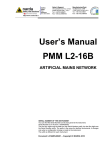
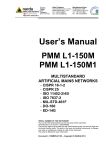
NARDA Safety Test Solutions S.r.l. Socio Unico Sales & Support: Via Leonardo da Vinci, 21/23 20090 Segrate (MI) - ITALY Tel.: +39 02 2699871 Fax: +39 02 26998700 Manufacturing Plant: Via Benessea, 29/B 17035 Cisano sul Neva (SV) Tel.: +39 0182 58641 Fax: +39 0182 586400 http://www.narda-sts.it User’s Manual PMM 6600 RF POWER METER 10 kHz - 1 GHz SERIAL NUMBER OF THE INSTRUMENT You can find the Series Number on the rear panel of the instrument. Series Number is in the form: 0000X00000. The first four digits and the letter are the Series Number prefix, the last five digits are the Series Number suffix. The prefix is the same for identical instruments, it changes only when a configuration change is made to the instrument. The suffix is different for each instrument. Document 6600EN-00705-1.10 – Copyright © NARDA 2007 NOTE: If the instrument is used in any other way than as described in this Users Manual, it may become unsafe Before using this product, the related documentation must be read with great care and fully understood to familiarize with all the safety prescriptions. To ensure the correct use and the maximum safety level, the User shall know all the instructions and recommendations contained in this document. This product is a Safety Class III and Installation Category II instrument according to IEC classification and has been designed to meet the requirements of EN61010-1 (Safety Requirements for Electrical Equipment for Measurement, Control and Laboratory Use). This product has a Pollution Degree II normally only non-conductive pollution occurs. Occasionally, however, a temporary conductivity caused by condensation must be expected. The information contained in this document is subject to change without notice. KEY TO THE ELECTRIC AND SAFETY SYMBOLS: You now own a high-quality instrument that will give you many years of reliable service. Nevertheless, even this product will eventually become obsolete. When that time comes, please remember that electronic equipment must be disposed of in accordance with local regulations. This product conforms to the WEEE Directive of the European Union (2002/96/EC) and belongs to Category 9 (Monitoring and Control Instruments). You can return the instrument to us free of charge for proper environment friendly disposal. You can obtain further information from your local NARDA Sales Partner or by visiting our website at www.narda-sts.it . Warning, danger of electric shock Earth Read carefully the Operating Manual and its instructions, pay attention to the safety symbols. Unit Earth Connection Earth Protection Equipotential KEY TO THE SYMBOLS USED IN THIS DOCUMENT: The DANGER sign draws attention to a potential risk to a person’s DANGER safety. All the precautions must be fully understood and applied before proceeding. WARNING The WARNING sign draws attention to a potential risk of damage to the apparatus or loss of data. All the precautions must be fully understood and applied before proceeding. CAUTION The CAUTION sign draws attention against unsafe practices for the apparatus functionality. NOTE: II The NOTE draw attention to important information. Note and symbols Contents General safety considerations and instructions......... EC Conformity Certificate……....................................... Page V VI 1 General Information 1.1 Documentation....................................................….... 1.2 Instruction Manual changes........................................ 1.3 Introduction………………........................................... 1.4 Instrument items........................................................ 1.5 Main specifications..................................................... 1.6 Front and rear panel................................................... 1.7 Functional description................................................. 1.8 Storage environment.................................................. Page 1-1 1-1 1-1 1-1 1-2 1-3 1-4 1-4 2 Installation 2.1 Introduction............................................................... 2.2 Initial inspection......................................................... 2.3 Packing and unpacking............................................. 2.4 Installation check list..............................................… 2.5 Environment......................…..................................... 2.6 Hardware installation.....…......................................... 2.7 Software installation........…....................................... 2.7.1 Confirm the directory name…………………………. 2.7.2 Installation completed message……………………. 2.7.3 PMM 6600 icon………………………………………. Page 2-1 2-1 2-1 2-1 2-1 2-1 2-2 2-2 2-3 2-3 3 Operating 3.1 Introduction................................................................. 3.2 Serial port connection.....…........................................ 3.2.1 Typical PMM 6600 display…………….................... 3.3 To connect PMM 6600 input to source………………. 3.3.1 PMM 6600 off or disconnected……………………... Page 3-1 3-1 3-1 3-1 3-2 4 Maintenance and Servicing 4.1 Return for service....................................................... 4.2 Equipment cleaning...............................….................. Page 4-1 4-1 5 Serial Communication Protocol 5.1 RS 232 protocol.........................…............................. 5.2 Calculation of power................................................... Page 5-1 5-1 Contents III Figures Figure 1-1 1-2 1-3 Page Front panel................................…...……........ Rear panel.................................…………....... Interconnection block diagram........................ 1-3 1-3 1-4 Tables Table Page Technical Specification…………………...…… 1-1 IV Contents 1-2 SAFETY RECOMMENDATIONS AND INSTRUCTIONS This product has been designed, produced and tested in Italy, and it left the factory in conditions fully complying with the current safety standards. To maintain it in safe conditions and ensure correct use, these general instructions must be fully understood and applied before the product is used. • When the device must be connected permanently, first provide effective grounding; • If the device must be connected to other equipment or accessories, make sure they are all safely grounded; • In case of devices permanently connected to the power supply, and lacking any fuses or other devices of mains protection, the power line must be equipped with adequate protection commensurate to the consumption of all the devices connected to it; • In case of connection of the device to the power mains, make sure before connection that the voltage selected on the voltage switch and the fuses are adequate for the voltage of the actual mains; • Devices in Safety Class I, equipped with connection to the power mains by means of cord and plug, can only be plugged into a socket equipped with a ground wire; • Any interruption or loosening of the ground wire or of a connecting power cable, inside or outside the device, will cause a potential risk for the safety of the personnel; • Ground connections must not be interrupted intentionally; • To prevent the possible danger of electrocution, do not remove any covers, panels or guards installed on the device, and refer only to NARDA Service Centers if maintenance should be necessary; • To maintain adequate protection from fire hazards, replace fuses only with others of the same type and rating; • Follow the safety regulations and any additional instructions in this manual to prevent accidents and damages. Safety consideration V EC Conformity Certificate (in accordance with the directives: EMC 89/336/EEC and low voltage 73/23/EEC) This is to certify that the product: PMM 6600 RF Power Meter 10 kHz - 1 GHz Produced by: NARDA S.r.l. Safety Test Solution Via Benessea 29/B 17035 Cisano sul Neva (SV) - ITALY complies with the following European Standards Safety: EN 60950 EMC: EN 55011 - EN 50082-1 This product complies with the requirements of the Low Voltage Directive 73/23/EEC, amended by 93/68/EEC, and the EMC Directive 89/336/EEC amended by 92/31/EEC, 93/68/EEC, 93/97/EEC. NARDA S.r.l. VI EC Conformity 1 - General Information 1.1 Documentation Enclosed with this manual are: • a service questionnaire to send back to NARDA in case of equipment service is needed • an accessories check list to verify all accessories enclosed in the packaging. 1.2 Instruction Manual changes Instruments manufactured after the printing of this manual may have a serial number prefix not listed on the title page; this indicates that instruments with different Serial Number prefix may be different from those documented in this manual. 1.3 Introduction The PMM 6600 is a simple and easy to use RF power measurement solution. It has been mainly designed for EMC application in order to calibrate CDNs and CLAMPs for conducted and induced immunity tests, or to measure input power forwarded to antennas or GTEMs cells. Using a directional coupler the forwarded as well the reflected input power can be also measured. Thanks to his internal temperature compensation, temperature drifting problems are overcome. NARDA supply simple but powerful drivers to be used with any WindowsTM environments. Just execute WindowsTM software and get your reading (dBm or Watt) into the PC monitor. If you are using PMM immunity software (conducted or radiated) all drivers are already embedded and ready to be used. 1.4 Instrument items PMM 6600 includes the following items: • PMM 6600 Power Meter; • PMM 6485 Interface; • Two RS232/485 cables; • Wall DC power supply (12VDC - 500 mA); • WindowsTM Drivers; • Operating Manual. Document 6600EN-00705-1.10 - © NARDA 2007 General information 1-1 1.5 Main specifications Table 1-1 lists the PMM 6600 performance specifications. The following conditions apply to all specifications: • The PMM 6600 needs at least a 15 minutes warm-up before operation. • The room temperature shall be 10° to 40° C. TABLE 1-1 Technical specifications Frequency Range 10 kHz to 1 GHz Power Level Range Connector 100 nW to 0,5 W (- 40 to +27 dBm) N (female) Maximum input Level 1 W (without damage) RF impedance Zin 50 Ω VSWR 1,25 Measuring error (10 kHz - 100 kHz) (100 kHz - 1 GHz) ± 1,5 dB (1 dB typical) ± 1 dB (0,5 dB typical) Power supply ± 12 VDC (from RS-485) Interface RS-485 (9 pin connector) Operating temperature 10° to 40° C PC required PC 486 with 4 Mbytes RAM and one available RS232 serial port Size 50 mm diameter, 120 mm long Weight 0,2 kg 1-2 General information 1.6 Front and rear panel Fig. 1-1 Front Panel Fig. 1-2 Rear Panel General information 1-3 1.7 Functional description PMM 6600 philosophy is based on high technology approach to offer high performance into small instrument. The block diagram give you an idea on how it works. Fig. 1-3 Interconnection block diagram 1.8 Storage Environment 1-4 The instrument should be stored in a clean and dry environment. The storage and shipping environment is specified to be within the following limitations: - 40° to + 50° C • Temperature < 95% relative • Humidity < 5.000 meters • Altitude General information 2 - Installation 2.1 Introduction This section provides the information needed to install your PMM 6600. Included are informations pertinent to initial inspection, power requirements, line voltage and fuse selection, power cables, interconnection, environment, instrument mounting, cleaning, storage and shipment. 2.2 Initial inspection To avoid any damage, do not turn on the instrument when there are signs of shipping damage to any portion of it. 2.3 Packing and Unpacking Inspect the shipping container for damage. If the shipping container or cushion material is damaged, it should be kept until the contents of the shipment have been checked for completeness and the instrument has been checked mechanically and electrically. Verify the accessories availability in the shipping referring to the accessories check list enclosed with the User Manual. Notify any damage to the carrier personnel as well as to NARDA Representative. 2.4 Installation Check list Before operation the following steps shall be taken: • Check the line voltage to ensure the compatibility with the equipment power supply operating voltage. A WARNING 2.5 Environment If this instrument is to be connected to other equipment or accessories, prior to energize either unit verify that a common ground exists between them. Any interruption or loosening of the protective earth ground conductor, either inside or outside the unit or in an extension cable will cause a potential shock hazard that could result in personal injury. The operating environment is specified to be within the following limitations: + 10° to + 40° C • Temperature < 90% relative • Humidity < 4’000 meters • Altitude 2.6 Hardware Installation PMM 6600 is delivered ready to use. Remove the Power Meter from his cardboard box and connect RS 485 cable to rear panel plug. Plug the opposite side of RS 485 cable in PMM 6485 interface module and connect RS 232 cable between PMM 6485 and PC serial port. Plug the provided DC power supplier to the mains wall outlet and to the PMM 6485 interface module. Refer to fig.1-3 for system interconnections Document 6600EN-00705-1.10 - © NARDA 2007 Installation 2-1 2.7 Software Installation PMM 6600 is provided with a simple Windows™ driver. This driver have to be installed before to use it. The procedure is: - insert the diskette into drive A; - invoke the program manager; - run the command File Run A:\Setup. 2.7.1 Confirm the directory name After few seconds the installation software will prompt the following window: Press Continue or type new directory name where the software should be installed. By default PMM proposes C:\WIN6600. 2-2 Installation When installation is complete you get the following window: 2.7.2 Installation completed message 2.7.3 PMM 6600 icon Click OK to confirm the installation. Then the driver will show the PMM 6600 icon. Click PMM 6600 icon to run the software. Installation 2-3 This page has been left blank intentionally 2-4 Installation 3 - Operating 3.1 Introduction Before starting to use the PMM 6600 RF power meter, provide for a correct hardware and software installation as recommended in Section 1. 3.2 Serial port connection By default software driver recognizes automatically PMM 6600 if connected at COM 2 serial port. If this serial port is already busy, click once on PMM 6600 icon and open Property window from Program Manager in Windows TM 3.11, or select the icon with the right mouse button and choose Property from menu in Windows TM 95, add the command COMM=N preceded by a space (in capital letters) at the end of the Destination field where N indicates the serial port to be used. Then confirm by selecting Apply. The assigned COM port nr. must be between 1 and 9. In other operating system the Destination field is enclosed in double quotation marks (“); in this case, the command COMM=N, preceded by a space must be outside. 3.2.1 Typical PMM 6600 display From Program Manager click on PMM 6600 icon. The software will then prompt: 3.3 To connect PMM 6600 input to source Connect the PMM 6600 input connector to the source you want to measure. The display will show the measured power expressed both in dBm and in Watt. Click EXIT if you want to terminate. Be sure not to apply more that 1 Watt to PMM 6600 input. A permanent damage could occur. Make sure that PMM 6600 input connector is well tight to the source N type RF connector. Grounding problems can cause wrong readings. Document 6600EN-00705-1.10 - © NARDA 2007 Operating 3-1 3.3.1 PMM 6600 off or disconnected If the power meter is off or disconnected from the PC you get the following message: Check all connections and DC power supply; then try again. 3-2 Operating 4 - Maintenance and Servicing 4.1 Return for service If the instrument should be returned to NARDA for service, please complete the service questionnaire enclosed with the User Manual and attach it to the instrument. To minimize the repair time, be as much specific as possible when describing the failure. If the failure only occurs under certain conditions, explain how to duplicate the failure. If possible, use of the original package to ship the equipment is preferable. In case other package should be used, ensure to wrap the instrument in heavy paper or plastic. Use a strong shipping container together with enough shock absorbing material all around the equipment, to provide a firm cushion and prevent movement in the container. To prevent damage during shipment in particular protect panels with display and connectors. Seal the shipping container securely. Mark the shipping container FRAGILE to encourage careful handling. 4.2 Equipment cleaning Use a non abrasive clean, soft and dry cloth for equipment cleaning. To clean the equipment do not use any solvent, thinner, turpentine, acid, acetone or similar matter to avoid damage to external enclosure. Document 6600EN-00705-1.10 - © NARDA 2007 Maintenance and Servicing 4-1 This page has been left blank intentionally 4-2 Maintenance and Servicing 5 - Serial Communication Protocol 5.1 RS 232 Protocol A reading of the measured RF power levels through any different software application can be also available using the following specifications to communicate via RS 232 with the 6600 Power Meter: • the communication is asynchronous and half duplex, where the computer is the master and the 6600 can only be the slave • the Baud Rate is 9600 with 8 bit for each string, 1 stop bit and no parity bit • the length of the strings is fixed, using the usual ASCII code from 00 to 127 (8FH); in dual configuration 6600+6600D, each string of the Primary unit (6600) starts with “#PM” and ends with “*”; instead, each string of the Secondary unit (6600D) starts with “#SM” and ends with “*”. By now the RF Power meter recognises up to 3 requests sent by the computer: 5.2 Calculation of Power #PMV* #SMV* to know type and firmware release number of the instrument; For the Primary unit, the answer is “ PMM6600 Vx ”, where “ x ” is the firmware release #PMp* #SMp* the answer are 2 bytes (H, the first transmitted, and L) to calculate the measured CW power (without modulation) #PMP* #SMP* the answer are 2 bytes (H, the first transmitted, and L) to calculate the measured modulated power The Power P have to be calculated as per the following formula: P= ( H ∗256 + L) − 1000 10 Example: At the enquiry “ #Pmp “ the 6600 answers “ 03H ” and “ 3FH” (3 and 63 in decimal), then the CW power (or the power without modulation correction) is P= (3∗256 + 63) − 1000 = − 16,9 dBm 10 Document 6600EN-00705-1.10 - © NARDA 2007 Serial Communication Protocol 5-1 This page has been left blank intentionally 5-2 Serial Communication Protocol NARDA Safety Test Solutions S.r.l. Socio Unico Sales & Support: Via Leonardo da Vinci, 21/23 20090 Segrate (MI) - ITALY Tel.: +39 02 2699871 Fax: +39 02 26998700 Manufacturing Plant: Via Benessea, 29/B 17035 Cisano sul Neva (SV) Tel.: +39 0182 58641 Fax: +39 0182 586400 http://www.narda-sts.it Mod. 18-1 Caro cliente grazie per aver acquistato un prodotto NARDA! Sei in possesso di uno strumento che per molti anni ti garantirà un’alta qualità di servizio. NARDA riconosce l'importanza del Cliente come ragione di esistenza; ciascun commento e suggerimento, sottoposto all'attenzione della nostra organizzazione, è tenuto in grande considerazione. La nostra qualità è alla ricerca del miglioramento continuo. Se uno dei Suoi strumenti NARDA necessita di riparazione o calibrazione, può aiutarci a servirla più efficacemente compilando questa scheda e accludendola all’apparecchio. Tuttavia, anche questo prodotto diventerà obsoleto. In questo caso, ti ricordiamo che lo smaltimento dell'apparecchiatura deve essere fatto in conformità con i regolamenti locali. Questo prodotto è conforme alle direttive WEEE dell’Unione Europea (2002/96/EC) ed appartiene alla categoria 9 (strumenti di controllo). Lo smaltimento, in un ambiente adeguato, può avvenire anche attraverso la restituzione del prodotto alla NARDA senza sostenere alcuna spesa. Può ottenere ulteriori informazioni contattando i venditori NARDA o visitando il nostro sito Web www.narda-sts.it. Dear Customer thank you for purchasing a NARDA product! You now own a high-quality instrument that will give you many years of reliable service. NARDA recognizes the importance of the Customer as reason of existence; in this view, any comment and suggestion you would like to submit to the attention of our service organization is kept in great consideration. Moreover, we are continuously improving our quality, but we know this is a never ending process. We would be glad if our present efforts are pleasing you. Should one of your pieces of NARDA equipment need servicing you can help us serve you more effectively filling out this card and enclosing it with the product. Nevertheless, even this product will eventually become obsolete. When that time comes, please remember that electronic equipment must be disposed of in accordance with local regulations. This product conforms to the WEEE Directive of the European Union (2002/96/EC) and belongs to Category 9 (Monitoring and Control Instruments). You can return the instrument to us free of charge for proper environment friendly disposal. You can obtain further information from your local NARDA Sales Partner or by visiting our website at www.narda-sts.it. 5 Servizio richiesto: 5 Service needed: Solo taratura Calibration only Riparazione Repair Riparazione & Taratura Repair & Calibration Taratura SIT Certified Calibration Altro: Other: Ditta: Company: Indirizzo: Address: Persona da contattare: Technical contact person: Telefono: Phone n. Modello: Equipment model: Numero di serie: Serial n. 5 Accessori ritornati con l’apparecchiatura: Nessuno Cavo(i) Cavo di alimentazione 5 Accessories returned with unit: None Cable(s) Power cable Altro: Other: 5 Sintomi o problemi osservati: 5 Observed symptoms / problems: 5 Guasto: Fisso Intermittente 5 Failure: Continuous Intermittent Sensibile a : Freddo Sensitive to: Cold Caldo Heat Descrizione del guasto/condizioni di funzionamento: Failure symptoms/special control settings description: Se l’unità è parte di un sistema descriverne la configurazione: If unit is part of system please list other interconnected equipment and system set up: Vibrazioni Altro Vibration Other Suggerimenti / Commenti / Note: Suggestions / Comments / Note: