1
i nsta l l a ti o n &
o perati ng i nstr ucti o ns
Armstrong Compass
5
auto (underfloor heating and two-pipe (parallel) systems)
auto function observes and adjusts the pump performance
to satisfy the system requirement. The pump adapts to the
system over time, it is recommended to leave the pump in
the auto position at least one week before selecting other
pump settings.
8. 2 venting the pump
Changing from recommended (auto) to alternative
pump setting:
Heating systems are 'slow' systems that cannot be set to the
optimum operation within minutes or hours.
Once the pump is vented (the noise has ceased), set the pump
mode according to the recommendations (see section 6).
If the recommended pump setting does not give the desired
comfort in some areas of the building, change the pump setting to the shown alternative.
See pump settings and pump performance (section 9) for
more details.
7.0 systems with bypass valve between flow and return pipes
Even with system vented, air may be still be present in the
pump. The air in the pump may cause noise but the noise
should cease after a few minutes running.
The venting process can be shortened by setting the pump to
run at speed III for a short period of time (20 seconds).
caution
The pump must not run dry.
9.0 pump settings and
pump performance
9.1 relation between pump setting
and pump performance
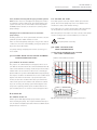
compass performance curves
7.5
7.1 purpose of bypass valve
A Compass circulator can eliminate the need for a differential
bypass valve when used in Auto or proportional pressure
modes, because the circulator will reduce speed when the
valves in the system close and the heat demand is reduced.
If you are servicing an existing system with a bypass valve
and you are replacing a fixed speed circulator with a Compass circulator, there is no need to remove the bypass valve.
8.0 start-up
8.1 before start-up
Fill the system with liquid and properly vent the system
before starting the pump. The required minimum inlet pressure in relation to liquid temperature must be available at the
pump inlet (see section 11).
6.5
6.0
5.5
head - meter (m)
The purpose of a differential pressure bypass valve is to ensure that the heat from the boiler can be distributed when all
valves in the underfloor-heating circuits and/or thermostatic
radiator valves are closed. These valves were commonly applied in multi zone systems with traditional fixed speed pumps.
7.0
5.0
4.5
pc3
pc4
4.0
3.5
3.0
2.5
auto
pc1
pc2
2.0
1.5
1.0
0.5
iii
i
ii
0
0
0.5
1.0
1.5
2.5
2.0
3.0
3.5
4.0
flow - m 3 /h
speed
pressure curve
iii
ii
pc4
pc2
i
pc3
pc1
au to
fig. 10 Pump setting in relation to pump performance
4.5
5.0