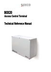
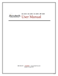
1
Temperature Monitor Temperature Monitor ° ° ° ° Reset POWER Supply & signal ALARM PT100 #1 Enter WARNING PT100 #2 PT100 #3 PT100 #4 Four PT100 temperature inputs Four alarm levels and four warning levels Individual high, low level or window Alarm and Warning function settings Readout of actual, min, average and max for temperatures Two dry contact relay outputs, for alarm and warning signaling Fast and easy installation - Magnets and standard M12 connectors Relays and Serial port galvanic isolated from the control system Built-in data logger - approx 114 days capacity Built-in RS485 interface for remote monitoring Suited for use in wind turbine nacelles or other harsh environments (-30°C…+70°C, vibration resistant and IP65 protected) O-LED display gives clear readout even in direct sunlight Temperature Monitor description The Temperature Monitor provides added surveillance to existing or new construction/machines (e.g. wind turbines) where critical parts need to be monitored (e.g. bearings or cooling liquid). Due to the magnets on the backside of the module, the Temperature Monitor can easily be mounted anywhere on a metal (iron) surface. All connections are done through prefabricated cables with moulded plugs to ensure a reliable and water tight connection (IP67). The PT100 sensors are delivered with 3 or 5 meter silicone cable (standard), complete with moulded M12 connector. Other cable length can be delivered on request. The Temperature Monitor is as standard delivered as a kit where all basic parts needed for installation is included. As standard two temperature sensors are included, if needed more sensors can be purchased separately. The Temperature Monitor is powered by 24VDC from the control system (e.g. from topbox or panel). Internally the system is galvanic isolated to prevent electrical surges (e.g. from lightning strike) from entering the control system. The signals to the control system (alarm and warning) are provided by galvanic isolated relay contacts (dry contacts). The signals and the power supply share the same cable to the topbox. The alarm output is wired to the external stop input of the turbine controller, using extra wires in the cable from topbox to CPU panel. If other equipment is connected to the external stop input, the relay contact from the Temperature Monitor can be connected in series. The relay contacts are Normally Closed. Function The Temperature Monitor has four temperature sensor inputs. A Warning level and an Alarm level can be set for each sensor. Furthermore a specific function can be selected for each sensor. Temperature HIGH – Trips when the temperature rises ABOVE the trip level. Temperature LOW - Trips when the temperature falls BELOW the trip level. Temperature WINDOW – Trips when the temperature moves OUTSIDE the window (Trip high or low). Disabled – No sensor attached (Not in use). The functions can be selected individually for Alarm and Warning for each sensor. Three examples are given for the working mode of the Alarm and Warning settings; The LOW trip, the HIGH trip and the Window functions. Study these three examples to gather knowledge of the functionality of the relay outputs. First example: ALARM is set to ‘Temp HIGH’ – triggers an alarm if the temperature increases above a certain level. WARNING is set to ‘Temp WINDOW’ – triggers a warning if the temperature moves outside the window limits. In the following paragraphs, the term ‘not defined state’ is used in the description of the Alarm and Warning RESET level. To achieve this, it is necessary to adjust the level setting of the function to the max. (190C) or min. (-40C) value. Then roll the value to the next step (the value between -40 and 190), and the display will show ‘---‘. This is the setting for ‘not defined’. Temperature HIGH function 1 ALARM FUNCTION HIGH Limit (Shown here: T1 Alarm relay is set to HIGH limit operation) First, make sure that the Alarm function of the Trip Config is set properly: MAIN PICTURE 1 3 31°C 57°C 2 4 54°C 17°C 1 MIN AVG MAX 26°C 62°C 78°C Reset Reset Reset Alarm / Warning Reset Reset Enter 1 RESET Hold 2s MIN/MAX (ENTER) Enter Reset values 1 (DONE) 1 ALARM TRIP LEVELS (ENTER) Reset Reset 1 WARNING TRIP LEVELS (ENTER) TRIP CONFIG (ENTER) Reset Reset Enter WARN. FUNCTION LOW Limit Enter Adjust Enter 1 1 ALARM FUNCTION HIGH Limit Reset Reset Enter NO FUNCTION HIGH Limit LOW Limit WINDOW Limit - NO ACTION ALARM/Man.RESET WARN./Man.RESET AL+WR/Man.RESET ALARM/AutoRESET WARN./AutoRESET AL+WR/AutoRESET Adjust Enter 1 SENSOR FAULT: ALARM/AutoRESET - Enter Adjust 54°C 17°C Reset Reset Reset Alarm / Warning 1 RESET Hold 2s MIN/MAX (ENTER) ALARM LEVELS TRIP (ENTER) 1 WARNING TRIP LEVELS (ENTER) MIN AVG MAX 26°C 62°C 78°C Reset Reset Reset values (DONE) 1 1 Enter Reset Reset Reset Reset Enter Enter Enter 1 TRIP CONFIG (ENTER) Reset Reset Enter If ’WINDOW Limit’ is selected 31°C 2 57°C 4 If ’LOW Limit’ is selected MAIN PICTURE 1 3 If ’HIGH limit’ is selected When this is set correct, then the working mode of the Alarm is selected: 1 ALARM TRIP LEVEL HI 90°C Enter 1 ALARM RESET LEVEL HI 80°C Enter 1 ALARM TRIP LEVEL LO 60°C Enter 1 ALARM RESET LEVEL LO ---°C Enter Adjust Adjust Adjust - --190 189 … -39 -40 --- Adjust When the temperature rises above the Alarm or Warning ‘TRIP’ level, the relay contact opens (in order to make it fail safe). The corresponding LED will also be lit, indicating the relay ‘open position’. If an Alarm or Warning ‘RESET’ level is defined, the relay contact closes when the temperature falls below the ‘RESET’ level (auto reset). The corresponding LED switches off. Left: RESET level defined. Right: No RESET level defined – here the Reset key needs to be pressed. For each input it is possible to have both an Alarm and a Warning level. In the below graph the Warning RESET is defined and the Alarm RESET level is not defined – this means that if the Alarm levels is reached, it is necessary for the service crew to reset the Temperature Monitor manually. If the warning level is reached the warning relay opens, and it closes again if the temperature falls below the RESET level (auto reset). The Alarm and Warning levels can be set in the range from -40..+190 C. When set above or below, the limit (trip or reset) is not active and the display shows ‘---‘. In the ‘TEST / CONFIG’ menu it is possible to force the outputs relays ‘OPEN’ or ‘CLOSED’ individually in order to test the connection to the control system. The relays will restore to their current positions according to the relevant measurements and settings when the menu is left. Temperature LOW function 1 ALARM FUNCTION HIGH Limit (Shown here: T1 Alarm relay is set to LOW limit operation) First, make sure that the Alarm function of the Trip Config is set according to the wanted function: MAIN PICTURE 1 3 31°C 57°C 2 54°C 4 17°C 1 MIN AVG MAX 26°C 62°C 78°C Reset Reset Reset Alarm / Warning Reset Reset 1 RESET Hold 2s MIN/MAX (ENTER) 1 (DONE) 1 ALARM TRIP LEVELS (ENTER) Enter Enter Reset values Reset Reset Enter Reset Reset Enter 1 1 WARNING TRIP LEVELS (ENTER) 1 TRIP CONFIG (ENTER) Reset Reset ALARM FUNCTION LOW Limit Enter WARN. FUNCTION LOW Limit Enter 1 SENSOR FAULT: ALARM/AutoRESET Enter Adjust - NO FUNCTION HIGH Limit LOW Limit WINDOW Limit - NO ACTION ALARM/Man.RESET WARN./Man.RESET AL+WR/Man.RESET ALARM/AutoRESET WARN./AutoRESET AL+WR/AutoRESET Adjust Enter Adjust 54°C 17°C Reset Reset Reset Alarm / Warning 1 RESET Hold 2s MIN/MAX (ENTER) Enter Reset values (DONE) 1 ALARM LEVELS TRIP (ENTER) 1 WARNING TRIP LEVELS (ENTER) 1 MIN AVG MAX 26°C 62°C 78°C Reset Reset Reset Reset Reset Reset Enter Enter Enter 1 TRIP CONFIG (ENTER) Reset Reset Enter If ’WINDOW Limit’ is selected 31°C 2 57°C 4 If ’LOW Limit’ is selected MAIN PICTURE 1 3 If ’HIGH limit’ is selected When this is set properly, the working mode of the Alarm is selected: 1 ALARM TRIP LEVEL HI 90°C Enter 1 ALARM RESET LEVEL HI 80°C Enter 1 ALARM TRIP LEVEL LO 60°C Enter 1 ALARM RESET LEVEL LO ---°C Enter Adjust Adjust Adjust - --190 189 … -39 -40 --- Adjust Mode of operation: When the temperature falls below the Alarm or Warning ‘TRIP’ level, the relay contact opens (in order to make it fail safe). The corresponding LED will also be lit, indicating the relay ‘open position’. If an Alarm or Warning ‘RESET’ level is defined, the relay contact closes when the temperature rises above the ‘RESET’ level (auto reset). The corresponding LED switches off. Left: RESET level defined. Right: The RESET level is not defined – here the Reset key needs to be pressed. For each input it is possible to have both an Alarm and a Warning level. In the below graph the Warning RESET is defined and the Alarm RESET level is not defined – this means that if the Alarm levels is reached, the service crew need to reset the Temperature Monitor manually. If the warning level is reached the warning relay is opened, and it closes again if the temperature falls below the RESET level (auto reset). The Alarm and Warning levels can be set in the range from -40…+190 C. When set above or below, the limit (trip or reset) is not active and the display shows ‘---‘. In the ‘TEST / CONFIG’ menu it is possible to force the outputs relays ‘OPEN’ or ‘CLOSED’ in order to test the connection to the control system. Temperature WINDOW function 1 ALARM FUNCTION WINDOW Limit (Shown here: T1 Alarm relay is set to WINDOW limit operation) Again, first thing to do is to set the Alarm function of the Trip Config correct: MAIN PICTURE 1 3 31°C 2 54°C 57°C 4 17°C 1 MIN AVG MAX 26°C 62°C 78°C Reset Reset Reset Alarm / Warning Reset Reset Enter 1 RESET MIN/MAX Hold 2s (ENTER) Enter Reset values 1 (DONE) 1 ALARM TRIP LEVELS (ENTER) Reset Reset Enter Reset Reset Enter 1 Reset Reset Enter MAIN PICTURE 31°C 2 54°C 57°C 4 17°C Reset Reset Reset Alarm / Warning 1 RESET MIN/MAX Hold 2s (ENTER) Enter Reset values (DONE) 1 ALARM TRIP LEVELS (ENTER) 1 WARNING TRIP LEVELS (ENTER) 1 MIN AVG MAX 26°C 62°C 78°C Reset Reset Reset Reset Reset Reset Enter Enter Enter 1 TRIP CONFIG (ENTER) Reset Reset Enter If ’WINDOW Limit’ is selected 1 3 If ’HIGH limit’ is selected 1 TRIP CONFIG (ENTER) Enter WARN. FUNCTION LOW Limit Enter 1 SENSOR FAULT: ALARM/AutoRESET If ’LOW Limit’ is selected 1 WARNING TRIP LEVELS (ENTER) FUNCTION Limit ALARM WINDOW Adjust - NO FUNCTION HIGH Limit LOW Limit WINDOW Limit - NO ACTION ALARM/Man.RESET WARN./Man.RESET AL+WR/Man.RESET ALARM/AutoRESET WARN./AutoRESET AL+WR/AutoRESET Adjust Enter Adjust 1 ALARM TRIP LEVEL HI 90°C Enter 1 ALARM RESET LEVEL HI 80°C Enter 1 ALARM TRIP LEVEL LO 60°C Enter 1 ALARM RESET LEVEL LO ---°C Enter Adjust Adjust Adjust - --190 189 … -39 -40 --- Adjust Then the settings of the levels can be made: Mode of operation When the temperature level rises above HIGH TRIP OR if it falls below the LOW TRIP setting, the Alarm or Warning relay contact opens (in order to make it fail safe). The corresponding LED will also be lit, indicating the relay ‘open position’. If an Alarm or Warning ‘RESET’ (HIGH/LOW) level is defined, the relay contact closes when the temperature moves within the two ‘RESET’ levels (auto reset), and the corresponding LED switches off. It is possible to have only one reset level, and one disabled. e.g. auto reset on low trip and manual reset on high trip. Left: RESET level defined. Right no RESET level defined – The Reset key needs to be pressed. To have the RESET level not defined, select the value between -40°C and 190°C in the “Warn. RESET” level field. For each input it is possible to have both an Alarm and a Warning level. In the below graph the Warning RESET HIGH/LOW and Alarm RESET low levels are defined. Alarm RESET HIGH is not defined – this means that if the Alarm HIGH level is reached, the service crew needs to reset the Temperature Monitor manually. However, if alarm LOW is reached, it will auto reset in the same way as if the warning level is reached, the warning relay is opened, and it closes again if the temperature moves within the RESET levels (auto reset). NOTE: In this example WARNING TRIP LOW and ALARM RESET LOW are set to the same temperature. Sensor fault function behavior For each sensor, it is possible to determine how the output should react in case of a faulty sensor (shorted or open circuit is defined as sensor fault). When a temperature sensor is disconnected, or if a sensor wire breaks, the display value will show ‘---‘ as an error indication for the current temperature sensor. If a faultless sensor is reconnected, either by itself (e.g. a periodic broken wire) or manually, the display value will flash between '---' and the measured temperature until the ‘Reset’ button is pressed. This indicates that the sensor has been faulty, but has recovered. The below list shows the possible settings for the sensor fault function: NO ACTION No reaction in case of sensor fault. Select this if no sensor is connected. ALARM/Man.RESET Alarm relay is opened in case of sensor fault – manual reset acquired (Press RESET). WARN./Man.RESET Warning relay is opened in case of sensor fault – manual reset acquired (Press RESET). AL+WR/Man.RESET Alarm and Warning relay is opened in case of sensor fault – manual reset acquired (Press RESET). ALARM/AutoRESET Alarm relay is opened in case of sensor fault – Resets automatically when the fault is removed/repaired. WARN./AutoRESET Warning relay is opened in case of sensor fault – Resets automatically when the fault is removed/repaired. AL+WR/AutoRESET Alarm and Warning relay is opened in case of sensor fault – Resets automatically when the fault is removed/repaired. The two relay contacts are common for all Alarm/Warning levels functions. This means that one or more alarm/warnings are able to open the relay contact. In case of trip or fault, the ‘normal’ display window will show an “A” or “!” sign to the right for the sensor number. This indicates that the actual sensor / function is causing an alarm or warning. In case of both alarm AND warning the display changes between “A” (Alarm) and "!" (Warning). Two LEDs on the front indicate the status of the alarm and warning relay. If lit = contact open. Temperature data The Temperature Monitor updates the actual temperature measurement approx. every second. The highest measured temperature is stored as ‘MAX’ and the lowest as ‘MIN’. At the same time an average temperature is calculated and is stored as ‘AVG’. MIN, MAX and AVG can be readout and, if decided, the values can be reset individually (manually). Every 5 minutes all three actual temperatures are stored in the internal memory (data logger). The memory contains 4 x 32767 values which are all temperatures, approx. 2730 hours back in time (equal to approx.114 days).The data can be extracted using the RS485 interface. The RS485 interface is intended for future connection to e.g. SCADA systems. For further information about the port, please contact us. Menu system The Menu structure of the Temperature Monitor is made as a tree structure. The four keys on the front is used to navigate, and in some cases also used to adjust values. Menu system overview Rev 2013-09-11 MAIN PICTURE 1 MIN AVG MAX 26°C 62°C 78°C Reset Reset 2 MIN AVG MAX 23°C 44°C 65°C Reset Reset 3 MIN AVG MAX 34°C 45°C 64°C Reset Reset 4 MIN AVG MAX 26°C 33°C 78°C 1 RESET MIN/MAX Hold 2s (ENTER) Reset Reset Reset Alarm / Warning Reset Reset Enter Reset values (DONE) 1 ALARM TRIP LEVELS (ENTER) Enter Enter 1 WARNING TRIP LEVELS (ENTER) 1 TRIP CONFIG (ENTER) Reset Reset Reset Reset Enter Enter Enter Reset Reset Enter If ’HIGH limit’ is selected 2 61°C 4 14°C If ’WINDOW Limit’ is selected 31°C 57°C If ’LOW Limit’ is selected 1 3 Enter Adjust: 1 ALARM TRIP LEVEL HI 60°C Enter 1 ALARM RESET LEVEL HI ---°C Enter 1 ALARM TRIP LEVEL LO 60°C Enter 1 ALARM RESET LEVEL LO ---°C Enter Adjust - Adjust --190 189 … -39 -40 --- Adjust Adjust Adjust/select up The settings of inputs 2, 3 and 4 equals input 1 Escape Reset Reset Enter Store Adjust/select down TEST / CONFIG (ENTER) Reset Reset TEST WARN. RELAY FORCE: CLOSED SYSTEM INFO Enter 1 WARN. FUNCTION LOW Limit Enter 1 SENSOR FAULT: ALARM/AutoRESET Enter Toggle output Enter Toggle output COMM (ENTER) Reset Reset MEMORY (ENTER) Reset Reset Reset Reset (ENTER) Enter Adjust - NO FUNCTION HIGH Limit LOW Limit WINDOW Limit - NO ACTION ALARM/Man.RESET WARN./Man.RESET AL+WR/Man.RESET NO ACTION ALARM/AutoRESET WARN./AutoRESET AL+WR/AutoRESET Enter TEST ALARM RELAY FORCE: OPEN SETUP 1 ALARM FUNCTION HIGH Limit Enter Enter Enter HW SW DATA DUMP DISABLED Enter SETUP MODULE Enter SETUP BAUD ID 244 RATE 19200 - Adjust - 0 - ... - 255 Adjust - 1200 - ... - 115200 Enter Adjust DEFAULT SETTINGS Hold 2s (ENTER) Default CLEAR LOG Hold 2s (ENTER) Clear DISABLED TYPE #1 TYPE #2 DUMP LOG Enter (DONE) Enter (DONE) Rev 2013-0218 Rev 2013-0911 SERIAL NO. 12345 PROD-WWYY 37.13 Reset Reset Enter DEBUG CMD - TC 00 ERR - Adjust Adjust ALARM TRIP LEVEL LO: ALARM TRIP LEVEL HI: ALARM RESET LEVEL HI: ALARM TRIP LEVEL LO: ALARM TRIP LEVEL LO: ALARM TRIP LEVEL HI: ALARM RESET LEVEL HI: ALARM TRIP LEVEL LO: ALARM TRIP LEVEL LO: ALARM TRIP LEVEL HI: ALARM RESET LEVEL HI: ALARM TRIP LEVEL LO: ALARM TRIP LEVEL LO: Temperature sensor #1 ALARM TRIP LEVEL LO: Temperature sensor #2 ALARM RESET LEVEL HI: Temperature sensor #3 ALARM TRIP LEVEL HI: Temperature sensor #4 Temperature sensor #4 Temperature sensor #3 Temperature sensor #2 Temperature sensor #1 My settings (See next page for default values) Warn. TRIP LEVEL HI: Warn. RESET LEVEL HI: Warn. TRIP LEVEL LO: - Warn. RESET LEVEL HI: Warn. TRIP LEVEL LO: Warn. RESET LEVEL HI: Warn. TRIP LEVEL LO: - Warn. RESET LEVEL HI: Warn. TRIP LEVEL LO: Warn. TRIP LEVEL LO: NO FUNCTION HIGH Limit LOW Limit WINDOW Limit SENSOR FAULT NO ACTION ALARM/Man.RESET WARN./Man.RESET AL+WR/Man.RESET ALARM/AutoRESET WARN./AutoRESET AL+WR/AutoRESET - NO FUNCTION HIGH Limit LOW Limit WINDOW Limit SENSOR FAULT - NO ACTION ALARM/Man.RESET WARN./Man.RESET AL+WR/Man.RESET ALARM/AutoRESET WARN./AutoRESET AL+WR/AutoRESET NO FUNCTION HIGH Limit LOW Limit WINDOW Limit SENSOR FAULT NO FUNCTION HIGH Limit LOW Limit WINDOW Limit - NO FUNCTION HIGH Limit LOW Limit WINDOW Limit WARN. FUNCTION - NO ACTION ALARM/Man.RESET WARN./Man.RESET AL+WR/Man.RESET ALARM/AutoRESET WARN./AutoRESET AL+WR/AutoRESET - NO FUNCTION HIGH Limit LOW Limit WINDOW Limit WARN. FUNCTION ALARM FUNCTION - - WARN. FUNCTION ALARM FUNCTION Warn. TRIP LEVEL LO: Warn. TRIP LEVEL HI: - ALARM FUNCTION Warn. TRIP LEVEL LO: Warn. TRIP LEVEL HI: NO FUNCTION HIGH Limit LOW Limit WINDOW Limit SENSOR FAULT Warn. TRIP LEVEL LO: Warn. TRIP LEVEL HI: WARN. FUNCTION ALARM FUNCTION - NO ACTION ALARM/Man.RESET WARN./Man.RESET AL+WR/Man.RESET ALARM/AutoRESET WARN./AutoRESET AL+WR/AutoRESET DATA DUMP SETUP MODULE ID SETUP BAUD RATE - NO FUNCTION HIGH Limit LOW Limit WINDOW Limit - DISABLED TYPE #1 TYPE #2 DUMP LOG - 0 : 255 - 1200 : 115200 Default values The values shown in the table refers to the default values of the Alarm and Warning functions. Alarm Setup: Alarm Hi Trip Alarm Hi Reset Alarm Lo Trip Alarm Lo Reset Warning Warning Warning Warning Hi Trip Hi Reset Lo Trip Lo Reset Function Setup: Alarm Function Warning Function Sensor Error: PT100 #1 75 65 0 0 PT100 #2 75 65 0 0 PT100 #3 75 65 0 0 PT100 #4 75 65 0 0 60 50 0 0 60 50 0 0 60 50 0 0 60 50 0 0 HIGH Lim HIGH Lim HIGH Lim HIGH Lim NO FUNCTION NO FUNCTION NO FUNCTION NO FUNCTION ALARM/Man.RES ALARM/Man.RES NO FUNCTION NO FUNCTION Technical Data Data Rating Range Notes Power supply voltage Current consumption Relay contact Temperature sensor 24VDC Approx. 70mA Max 0.1A/30V PT100 2/4W 18…34VDC 2,2W max (AC/DC) -40…+190°C Connections Tower base Nacelle Topbox / panel Controller panel Temperature Monitor WH - +24VDC PT100 #1 Main bearing PT100 #2 Gear front bearing PT100 #3 Gear rear bearing PT100 #4 Ambience BN - 0VDC Ext. stop Tower cable GY - Alarm YE - Warning Input GN - COM +24VDC PK – RS485 ’A’ BU – RS485 ’B’ RS485 RD – RS485 com M12-8 cable 8 pole M12 Pin 1 White Pin 2 Brown Pin 3 Green Pin 4 Yellow Pin 5 Gray Pin 6 Pink Pin 7 Blue Pin 8 Red +24VDC, Supply 0VDC, Supply Relay common Warning relay, NO Alarm relay, NO RS485 'A'/'+' RS485 'B'/'-' RS485 GND 8 pole M12 for Pin 1 Brown Pin 2 White Pin 3 Blue Pin 4 Black temperature sensors Signal 1 PT100 Signal 2 PT100 Signal 3 PT100 Signal 4 PT100 RS485 port Standard 2-wire RS485 levels. Serial protocol Contact us for further information. (isolated (isolated (isolated (isolated (isolated (isolated (isolated (isolated from from from from from from from from side side side side A B B A ground) ground) supply and supply and supply and supply and supply and supply and ground) ground) ground) ground) ground) ground) RED 1 RED 4 PT100 w/cable WHITE 3 WHITE 2 Outline 1 2 52°C 65°C 3 4 48°C 39°C Reset POWER ALARM Enter 64 Temperature Monitor WARNING SPICA TECHNOLOGY Supply & signal PT100 #1 PT100 #2 150 PT100 #3 PT100 #4 43 All dimensions in mm 0813029 0513029 UM 2013-11-18