1
AIR FORCE HANDBOOK 32-4014, Volume 3
1 February 1998
USAF OPERATIONS IN A CHEMICAL AND
BIOLOGICAL (CB) WARFARE ENVIRONMENT,
DEFENSE EQUIPMENT
DEPARTMENT OF THE AIR FORCE
BY ORDER OF THE
SECRETARY OF THE AIR FORCE
AIR FORCE HANDBOOK 32-4014, VOLUME 3
1 FEBRUARY 1998
Civil Engineer
USAF OPERATIONS IN A CHEMICAL AND BIOLOGICAL
WARFARE ENVIRONMENT, DEFENSE EQUIPMENT
This handbook implements AFPD 32-40, Disaster Preparedness and
AFMAN 32-4005, Personnel Protection and Attack Actions. AFH 32-4014,
Volume 3, provides Civil Engineer Readiness Flight personnel with general
information and technical data concerning fielded chemical and biological
warfare defense equipment. The information contained in this guide was
extracted from various Air Force Technical Orders and/or equipment
manuals. The information contained herein does not supersede any
published Technical Order (T.O.), Readiness Training Package (RTP), or
equipment manual. Information on planning and analysis, hazards, and
defense procedures can be found in Volumes 1, 2, and 4, respectively.
CHAPTER 1 - GENERAL INFORMATION ..........................................3
1.1. INTRODUCTION. ..............................................................................3
1.2. HISTORICAL PRECEDENCE AND THE THREAT TODAY. ........................3
CHAPTER 2 - INDIVIDUAL PROTECTIVE EQUIPMENT ................4
2.1. GROUNDCREW CHEM-DEFENSE ENSEMBLE (GCE)............................4
2.2. JOINT SERVICE LIGHTWEIGHT INTEGRATED SUIT TECHNOLOGY
OVERGARMENT (JSLIST OG)..................................................................8
2.3. MASK, MCU-2A/P........................................................................13
2.4. MASK, M17A2..............................................................................21
CHAPTER 3 - INDIVIDUAL DETECTION EQUIPMENT.................29
3.1. M8 PAPER, CHEMICAL AGENT DETECTION .....................................29
3.2. M9 CHEMICAL AGENT DETECTOR PAPER .......................................32
OPR: HQ AFCESA/CEXR (MSgt Steve Reed)
Certified by: HQ AFCESA/CEX (Colonel Randall L. Turner)
Pages: 100/Distribution: F
2
AFH 32-4014, Volume 3, 1 February 1998
3.3. M256A1 CHEMICAL AGENT DETECTOR KIT ...................................35
CHAPTER 4 - DECONTAMINATION EQUIPMENT ........................40
4.1.
4.2.
4.3.
4.4.
M258A1 PERSONAL DECONTAMINATION KIT .................................40
M291 SKIN DECONTAMINATING KIT ..............................................44
M295 INDIVIDUAL EQUIPMENT DECONTAMINATION KIT .................48
M17 DECONTAMINATING APPARATUS ............................................50
CHAPTER 5 - SPECIALIZED DETECTION EQUIPMENT ..............53
5.1.
5.2.
5.3.
5.4.
5.5.
5.6.
5.7.
5.8.
5.9.
AUTOMATIC LIQUID AGENT DETECTOR (ALAD) ............................53
CHEMICAL AGENT MONITOR (CAM) .............................................58
M8A1 CHEMICAL AGENT ALARM ..................................................61
M90 CHEMICAL AGENT DETECTOR................................................66
M22 AUTOMATIC CHEMICAL AGENT DETECTOR ALARM ................71
BIOLOGICAL WARFARE AGENT DETECTION ....................................75
CHARGER CDV-750/750-5 ............................................................77
DOSIMETER, IM 143PD.................................................................80
ADM 300, MULTI FUNCTIONAL RADIAC METER (MFR) ..............83
CHAPTER 6 - SUPPORT EQUIPMENT ..............................................90
6.1.
6.2.
6.3.
6.4.
M41 PROTECTION ASSESSMENT TEST SYSTEM ...............................90
NBC CONTAMINATION MARKING SET............................................92
MULTI-MAN INTERMITTENT COOLING SYSTEM (MICS)..................94
AN/PSN-11 NAVIGATION SET GLOBAL POSITIONING SYSTEM ........97
AFH 32-4014, Volume 3, 1 February 1998
3
CHAPTER 1 - GENERAL INFORMATION
1.1. Introduction.
The threat of the use of chemical and biological weapons occurs across the
spectrum of military operations. The number of nations capable of
developing and possessing these weapons is steadily increasing. Nations
are receiving these weapons, or means to develop them, through
technological transfer, overt or covert direct transfer, or support to
belligerent groups or governments. The potential for their use ranges from
blackmail or acts of terrorism during peace to escalation during conflict or
war.
1.2. Historical Precedence and the Threat Today.
Chemical and biological (CB) operations are not new. Historical records
show use of chemicals, smoke, and flame in warfare. During World War I,
the Allies and the Germans used them extensively. Many nations developed
and manufactured agents during World War II, and some have used these
agents since then. CB weapons capabilities, once available to only a select
few of the world’s most militarily powerful nations, today are in the hands
of several emerging and developing nations.
1.2.1. It is increasingly likely the United States could encounter the use of
CB at the operational and tactical levels in a regional conflict. Use of these
weapons at the operational level could be against rear area targets such as
air bases, considered critical to US efforts but far enough removed to permit
the use without seriously jeopardizing the attacker’s forces. The objective
of a CB attack against USAF forces would likely be to cause casualties and
degrade operations, greatly reducing sortie generation rates and denying the
US the critical advantage of air superiority.
4
AFH 32-4014, Volume 3, 1 February 1998
CHAPTER 2 - INDIVIDUAL PROTECTIVE EQUIPMENT
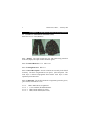
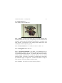
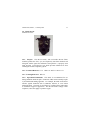
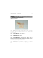
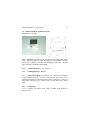
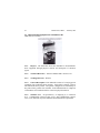
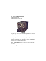
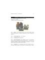
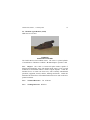
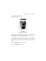
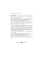
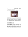
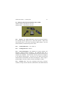
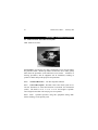
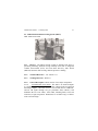
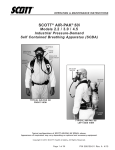
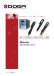
2.1. Groundcrew Chem-Defense Ensemble (GCE)
BDO 8415-01-137-1704 (Medium)
2.1.1. Purpose. The GCE provides the user with whole body protection
from solid, liquid, and vapor wartime chemical agents.
2.1.2. Technical Reference. T.O. 14P3-1-141
2.1.3. Training Reference. RTP C11
2.1.4. General Description. Several variations are currently in the USAF
inventory. The basic overgarment has two pieces: jacket and pants. The
inner layer is charcoal impregnated foam and the outer layer is water
repellent nylon/cotton twill.
2.1.5. Components. The GCE includes the overgarment, protective gloves,
glove inserts, and footwear covers.
2.1.5.1. BDO: Battle Dress Overgarment.
2.1.5.1.1. 8 sizes available, Woodland Pattern.
2.1.5.1.2. BDO, Desert Pattern (six color).
2.1.5.1.3. BDO, Desert Pattern (three color).
AFH 32-4014, Volume 3, 1 February 1998
5
2.1.5.2. Protective gloves: butyl rubber, gauntlet style. Two types: 7 mil
and 14 mil thickness. There are four sizes available (small, medium, large,
extra large)
2.1.5.2.1. 7 mil provides more dexterity.
2.1.5.2.2. 14 mil are standard issue.
2.1.5.3. Glove inserts: cotton, gauntlet style, three sizes available (small,
medium and large).
2.1.5.4. Footwear covers: come in three types: four eyelet, five eyelet,
and green or black vinyl overshoes (GVOs/BVOs).
2.1.5.4.1. Four eyelet type, two sizes: small and large.
2.1.5.4.2. Five eyelet type, two sizes: small and large.
2.1.5.4.3. GVO/BVO, available in 12 full sizes (3-14) -- no half sizes
available.
2.1.5.3. Multipurpose Overboot (MULO): A one-piece overboot worn
over combat or field boots utilizing an integrated strap/clip closure system.
2.1.5.3.1. Future fielding item that will replace current overboots.
2.1.6. Wartime User. All personnel in, or deploying to, a CB threat area.
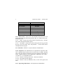
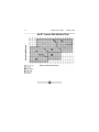
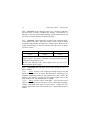
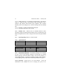
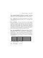
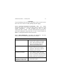
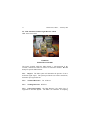
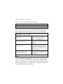
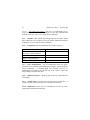
2.1.7. Fit. Proper size of GCE components is essential to provide whole
body protection. The table below describes proper fit of overgarment:
6
AFH 32-4014, Volume 3, 1 February 1998
Waist sizes.
Up to 19 inches
19 to 23 inches
23.1 to 27 inches
27.1 to 31 inches
31.1 to 35 inches
35.1 to 39 inches
39.1 to 43 inches
43.1 inches Up
Sizes.
XXX Small
XX Small
X Small
Small
Medium
Large
X Large
XX Large
2.1.8. Service Life. Service life is the amount of time the GCE will
provide protection once taken from protective bag. It is influenced by wear,
not exposure to air.
2.1.8.1. BDO: 22 days once removed from its protective bag. 24 hours
after contact with liquid chemical agents.
2.1.8.2. GVO/BVO: 14 days once removed from protective bag, provided
the bag is free from cracks, tears, and punctures. 12 hours after contact
with liquid chemical agents.
2.1.9. Shelf Life. Shelf life is 14 years after date of manufacturer.
2.1.10. Inspection. The individual user is responsible for inspection of the
GCE. Inspection must be done prior to use and every 12 months. Do Not
remove any item from its factory bag for the sole purpose of inspection or
sizing. Complete inspection of all components is identified in T.O. 14P3-1141, Table 5-1. As a minimum ensure:
2.1.10.1. Absence of wetting, holes, tears. Check for cleanliness.
2.1.10.2. All fasteners operate properly.
2.1.10.3. Absence of dry rot, brittleness, holes, or tears in the gloves and
boots.
2.1.11. Operating Temperatures. All temperatures and humidities.
AFH 32-4014, Volume 3, 1 February 1998
7
2.1.12. Donning/Doffing, Decontamination, Operational Use. Complete
procedures are identified in T.O.14P3-1-141. Failure to follow T.O.
procedures could result in contamination to the individual.
8
AFH 32-4014, Volume 3, 1 February 1998
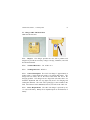
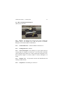
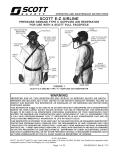
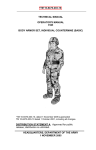
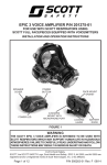
2.2. Joint Service Lightweight Integrated Suit Technology
Overgarment (JSLIST OG)
8415 01 444 1238 (Medium regular coat, woodland)
8415 01 444 2310 (Medium regular trousers, woodland)
2.2.1. Purpose. The JSLIST OG provides the user with whole body
protection from both liquid and vapor wartime chemical agents.
2.2.2. Technical Reference. T.O. 14P3-1-171
2.2.3. Training Reference. C14 (when published)
2.2.4. General Description. The JSLIST OG is a two-piece, coat and
trousers, overgarment with an integral hood that is compatible with existing
protective masks. The coat and trousers are issued separately, but worn
together as a uniform. The overgarment is made of permeable materials.
2.2.5. Components. The ensemble includes the JSLIST OG, protective
gloves, glove inserts, and footwear covers.
2.2.5.1. JSLIST OG Coat: 7 sizes available, Woodland Pattern. 7 sizes
available, Desert Pattern.
2.2.5.2. JSLIST OG Trousers: 7 sizes available, Woodland Pattern. 7
sizes available, Desert Pattern.
AFH 32-4014, Volume 3, 1 February 1998
9
2.2.5.3. Protective gloves: butyl rubber, gauntlet style. Two types: 7 mil
and 14 mil thickness. 7 mil provides more dexterity. 14 mil are standard
issue. There are four sizes available (small, medium, large, extra large)
2.2.5.4. Improved CB Protective Glove (ICBPG): A semi-permeable
glove in an integrated glove design. Future fielding item that will replace
rubber glove/Inserts by attrition.
2.2.5.5. Glove inserts: cotton, gauntlet style, three sizes available (small,
medium and large)
2.2.5.6. Footwear covers: come in three types: four eyelet, five eyelet,
and green or black vinyl overshoes (GVOs/BVOs): Four eyelet type, two
sizes: small and large. Five eyelet type, two sizes: small and large.
GVO/BVO, available in 12 full sizes (3-14) -- no half sizes available.
2.2.5.7. Multipurpose Overboot (MULO): A one-piece overboot worn
over combat or field boots utilizing an integrated strap/clip closure system.
Future fielding item that will replace current overboots.
2.2.6. Wartime User. All personnel in, or deploying to, a CB threat area.
2.2.7. Service Life. Service life is the amount of time the JSLIST will
provide protection once taken from protective bag. It is influenced by wear,
not exposure to air.
Uncontaminated wear time
Whichever comes first:
After 6
45 day wear
60 day service
10
launderings
life
year shelf life
Contaminated wear time:
24hrs (regardless of type of contamination).
GVO/BVO: 14 days once removed from protective bag, provided the bag
is free from cracks, tears, and punctures. 12 hours (extendible to 24)
after contact with liquid chemical agents.
10
AFH 32-4014, Volume 3, 1 February 1998
2.2.8. Inspection. The individual user is responsible for inspection of the
GCE. Inspections must be done prior to use and every 12 months. Do Not
remove any item from its factory bag for the sole purpose of inspection or
sizing. As a minimum ensure:
2.2.8.1. Absence of wetting, holes, tears. Check for cleanliness.
2.2.8.2. All fasteners operate properly.
2.2.8.3. Brittleness, holes, or tears in the gloves and boots.
2.2.8.4. Complete inspection of all items listed in T.O. 14P3-1-171.
2.2.9. Operating Temperatures. All temperatures and humidities.
2.2.10. Donning/Doffing, Decontamination, Operational Use. Complete
procedures are identified in T.O.14P3-1-171. Failure to follow T.O.
procedures could result in contamination to the individual.
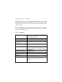
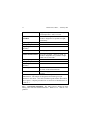
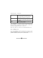
2.2.11. Fit. Proper size of JSLIST components is essential to provide
whole body protection.
The tables below describes proper fit of
overgarment:
AFH 32-4014, Volume 3, 1 February 1998
11
12
AFH 32-4014, Volume 3, 1 February 1998
AFH 32-4014, Volume 3, 1 February 1998
13
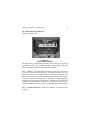
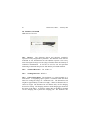
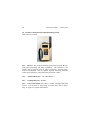
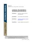
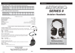
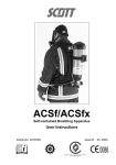
2.3. Mask, MCU-2A/P
2A/P: 4240-01-284-3615 thru 3617
2.3.1. Purpose. The MCU-2A/P mask with a serviceable canister filter
installed protects the faces, eyes, and respiratory tract from chemical and
biological warfare agents and radioactive dust particles. A properly worn
mask provides a gas-tight face seal which prevents unfiltered air from
reaching the wearer’s respiratory system.
2.3.2. Technical Reference. T.O. 14P4-15-1 and T.O. 14P4-1-151
2.3.3. Training Reference. RTP C10
2.3.4. Operational Limitations. This mask is not authorized for use
during industrial chemical spills. Chemicals of this nature normally require
a self-contained breathing apparatus. For example, the mask would not be
effective against chemicals such as ammonia, chlorine, or even carbon
monoxide fumes. The mask is not effective in confined spaces when there
is insufficient oxygen to support life. The MCU-2A/P mask is simply a
filter respirator; it does not supply or produce oxygen.
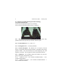
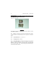
2.3.5. Features. The MCU-2A/P has the following features:
14
AFH 32-4014, Volume 3, 1 February 1998
2.3.5.1. Two voicemitters: the front one is for face-to-face speech and
the side one is for use with communications equipment.
2.3.5.2. Flexible lens: permits use of binoculars, a gunsight, or other
optical equipment.
2.3.5.3. Drinking tube: enables the user to drink from a canteen having
an M1 canteen cap.
2.3.6. Mask Size. The mask comes in three sizes (short, medium, long).
Correct mask size is determined by facial measurements. A spring caliper,
vernier dial, and/or the M-41 Protection Assessment Test System (PATS) is
required to determine proper fit. Proper mask size will be determined upon
issue.
2.3.7. Inspection and Documentation. The user must inspect the mask
upon issue, every six months during peacetime, and every seven days during
wartime.
Document the mask’s inspection on a DD Form 1574
(Serviceability Tag) or data automated product. When a serviceable C-2
canister is installed, annotate the canister lot number and the date it was
installed in the remarks section of the DD Form 1574 or in an area
designated on the data automated form.
2.3.8. Familiarization and Inspection of Components. The MCU-2/AP
mask consists of the following components:
2.3.8.1. Facepiece: The facepiece is molded of silicone rubber which
forms an effective seal on the face. Ensure it’s not cracked or deteriorated.
2.3.8.2. Head Harness: The head harness holds the mask to the face. It
has six elastic straps, a headpad, and a quick-don pull tab. Ensure the head
harness has elasticity for a proper seal.
2.3.8.3. Voicemitters: Voicemitters are located on the center and either
side of the facepiece. The voicemitters transmit the user’s voice outside the
mask. The side voicemitter is useful when using phones, radios, or other
communications equipment. Always make sure these voicemitters aren’t
damaged and are tightly seated.
AFH 32-4014, Volume 3, 1 February 1998
15
2.3.8.4. Outlet Valve Assembly: The outlet valve assembly has a one-way
valve at the bottom of the facepiece. The valve should be replaced if it’s
damaged or doesn’t seat properly.
2.3.8.5. Outlet Valve Cover: The outlet valve cover is a rubber cover that
holds the drinking tube coupling. It fits over the end of the outlet valve
body and can be easily replaced if torn, dry rot or otherwise damaged.
2.3.8.6. Drinking Tubes: The external and internal drinking tubes are
rubber tubes used with the M1 canteen cap to provide water to the wearer.
The tubes shouldn’t have any breaks or leaks in it.
2.3.8.7. Nosecup: The nosecup is made of silicone rubber and is located
inside the facepiece. The nosecup helps prevent the mask from fogging by
allowing air to enter through two nosecup valves and keeping warm air off
the eyelens. This is not a replacement item.
2.3.8.8. Inlet Valve Assembly: The inlet valve assembly consists of a
one-way valve disc and an air deflector assembly. As always, when
inspecting any disks make sure they’re flat; not ripped or curled.
2.3.8.9. Lens: The lens is made of transparent urethane and provides a
wide field of vision. The lens must be free from stains, excessive scratches,
and cracks.
2.3.8.10. Outsert: Check for scratches and damage.
2.3.8.11. Canister. The C-2 canister is made with layers of impregnated
charcoal which provide the filtration. The canister must be free from dirt,
debris, and water. Check it for physical damage around the seams and
threads.
2.3.9. Accessories. The mask also has the following accessories:
2.3.9.1.
Mask carrier.
2.3.9.2.
Protective hood.
2.3.9.3.
Mask outsert. The outserts are clear or tinted polycarbonate
shells. The outserts protect the lens from scratches, chemical droplets, and
oil and petroleum products.
2.3.9.4.
Special canteen cap. The MCU-2A/P is designed to allow the
wearer to drink from a canteen while wearing the mask. The canteen must
have the M1 cap installed in order to use the drinking system.
16
AFH 32-4014, Volume 3, 1 February 1998
2.3.9.5.
Waterproofing bag. The waterproofing bag will be used to store
the mask when operating in extremely wet areas. This will protect the filter
elements from getting wet.
2.3.9.6.
Spectacles inserts.
2.3.10. Wartime User. All personnel in, or deploying to, a CB threat
area.
2.3.11. Care and Use. When the MCU-2A/P series mask is issued, all
maintenance is the responsibility of the user.
2.3.12. Operational Factors. The MCU-2A/P series mask remains
serviceable as long as it meets operational inspection IAW T.O. 14P4-15-1.
C2 canister(s) must be replaced after CB contamination or shelf life
expiration.
2.3.12.1.
When directed by higher authority or a clear indication of
chemical use.
2.3.12.2.
15 days have elapsed after exposure to chemical-biological
agents (except blood agent)
2.3.12.3.
Exposure to BLOOD agent has occurred.
2.3.12.4.
Shows evidence of mechanical damage such as breaks or cuts
in material or edge of seal, a bent or split connector, etc.
2.3.12.5.
Immersed in water or wetted in anyway.
2.3.12.6.
Excessive breathing restriction is experienced.
2.3.12.7.
Filters have been exposed for two months in tropical climates.
(Panama, Puerto Rico, etc.)
2.3.12.8.
Filters have been exposed for 12 months in temperate climates.
(Korea, Europe, etc.)
2.3.12.9.
Filters have been exposed for 24 months in arctic climates.
(Alaska, etc.)
2.3.13. Fitting. With the mask ready for fitting (canister installed, head
harness straps loose and reversed over the front of the mask, and the outsert
removed) you can fit the mask as follows:
AFH 32-4014, Volume 3, 1 February 1998
17
2.3.13.1.
Place mask on face, keeping the hair out of the way and pull
the head harness over the head using the quick don tab.
2.3.13.2.
Tighten temple straps, one at a time, using small jerking pulls
until the mask feels snug.
2.3.13.3.
Check that the headpad is centered at the high point of rear of
head. Adjust if necessary.
2.3.13.4.
Tighten the neck straps then the forehead straps in the same
manner.
2.3.13.5.
The mask should be comfortable on the face with no straps
cuttings or pinching. The mask should not be so tight the nosecup presses
painfully on the nose.
2.3.13.6.
While wearing the mask, with the head harness properly
adjusted, check the internal and external drinking tubes for a secure fit.
2.3.13.7.
The last thing to check when fitting the mask is to perform a
negative pressure check ("leak check") by pressing your palm over the end
of the canister and inhaling. The mask will deflect and you shouldn’t feel
any air entering your mask. You will have to check and adjust your mask if
leaks occur.
2.3.13.8.
You can now remove the mask. Loosen ONLY the mask neck
straps. Grasp mask by pulling outlet valve assembly and remove by pulling
down, outward, and up.
2.3.14. Donning And Doffing Mask (With Hood Attached). Due to the
short time it takes for toxic agents to affect you, becoming an expert in
donning the mask and getting an air tight seal is imperative. With
suspected contamination, every step in donning the mask is important and
must be done quickly and accurately. You must put the mask on before you
take another breath.
WARNING
Perform the steps for putting on our mask quickly. You must put the mask
on before you take another breath. Toxic agents may be in the surrounding
air and cause sickness or death.
18
AFH 32-4014, Volume 3, 1 February 1998
2.3.14. Donning. Donning the mask with hood attached should take place
in 15 seconds. This allows you to don the mask and get an airtight seal in
nine seconds with an additional six seconds to pull the hood over the head
and tighten the neck cord. Follow these steps in this order:
2.3.15.1.
STOP BREATHING!
2.3.15.2.
Close eyes tightly.
2.3.15.3.
Remove headgear.
2.3.15.4.
Remove mask and hood from carrier.
2.3.15.5.
Hold outlet valve assembly in palm of one hand. Using free
hand, push forehead hair aside. Place mask on face forcing the chincup
very tightly against chin. Pull headharness over head using the quick-don
tab.
2.3.15.6.
Grasp a neck strap in each hand and tighten with small
jerking motions. The neck straps should be the only straps adjusted.
Temple and forehead straps are adjusted when you fit the mask and then left
in position.
2.3.15.7.
Expel air held in the lungs.
2.3.15.8.
Press palm of one hand over the canister opening. Inhale to
determine whether an airtight seal of mask against face has been obtained.
2.3.15.9.
Open eyes and RESUME NORMAL BREATHING.
2.3.15.10. Pull back of hood over your head so the hood covers your
head. Drape cape over shoulders. Make sure the cape is under neck cord.
2.3.15.11. Use neck cord fastener to tighten neck cord until hood is held
snugly around neck.
2.3.15.12. Pass straps under arms. Fasten ends to front of cape.
2.3.15.13. Replace headgear and close the carrier.
WARNING
You must check the mask for leaks when it is fitted and each time you put it
on. A leaky mask will not protect you from toxic agents which can cause
sickness or death.
AFH 32-4014, Volume 3, 1 February 1998
19
2.3.16. Doffing. Doffing the mask involves these five steps:
2.3.16.1.
Unfasten underarm straps and loosen neck cord.
2.3.16.2.
Pull back of cape forward over head and leave hood suspended
from front of mask.
2.3.16.3.
Loosen ONLY the mask neck straps. Grasp mask by pulling
outlet valve assembly and remove by pulling down, outward, and up.
2.3.16.4.
Shake or wipe any moisture or frost accumulations from inside
of hood and mask.
2.3.16.5.
Properly stow mask in carrier.
2.3.17. Hood. To increase operational efficiency, you must make sure
certain adjustments to the hood based on temperatures. In moderate
temperature (between 30o to 90o degrees Fahrenheit), place the hood over
the voicemitter/outlet valve cover. The exhausted air inflates the hood and
helps prevent contaminated air from entering the hood. In extreme weather
-- cold (below 30o F) or hot (above 90o F), uncover the voicemitter/outlet
valve cover. In cold weather, this prevents condensed moisture from
freezing inside the hood or from dripping into your clothing. In hot
weather, it prevents extreme heat and humidity buildup inside the hood.
2.3.18. Repair. The mask has no repair parts. All repair is accomplished
using replacement parts. Defective parts other than those listed in the T.O.
are cause for mask replacement. If mask replacement is required keep all
serviceable parts – replacement masks only include the facepiece.
2.3.18.1.
Have the proper size. Ensure you have a proper size mask by
using the proper measuring caliper. A leaking mask will not protect against
toxic agents.
2.3.18.2.
Don't over tighten the mask. Over tightening may actually
cause leaks.
2.3.18.3.
Check the mask for leaks every time you put it on by
performing your negative pressure or "leak" check.
20
AFH 32-4014, Volume 3, 1 February 1998
2.3.18.4.
Don the mask quickly. Remember it should be on and sealed
before you take another breath.
2.3.18.5.
Remember the limitations. The MCU-2/P Series Mask is not
intended for industrial chemical use and is not effective in confined spaces
where there is not enough oxygen to support life.
2.3.18.6.
When wearing the mask with the hood over the outlet valve do
not loosen the straps of the head harness for comfort. If the straps are
loosened, the wearer is in danger of suffocation by carbon dioxide and
unprotected against toxic agents.
2.3.18.7.
If you become overheated in cold weather, do not remove your
mask outdoors until your head cools and sweat has dried. Frostbite may
result if the mask is removed while your face is still wet.
2.3.18.8.
A serviceable C-2 canister must be installed in the MCU-2/P
Series Mask prior to use in a toxic chemical or biological environment.
2.3.19. Cleaning. Clean the mask with mild liquid detergent and warm
water. Alcohol towelettes may be used for expedient sanitation. Do not
place the mask in boiling water. Do not wash the canister. Do not dry wipe
the mask lens to avoid scratching.
2.3.20. Decontamination. The mask and hood should be decontaminated
as soon as practical after CB contamination has occurred. Perform
immediate decontamination using the M258A1 or M295 decontamination
kits. Perform operational and thorough decontamination in accordance
with the T.O.
AFH 32-4014, Volume 3, 1 February 1998
21
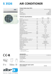
2.4. Mask, M17A2
4240-01-143-2017
2.4.1. Purpose. The M17A2 mask, with serviceable M13A2 filters
installed, protects the faces, eyes, and respiratory tract from chemical and
biological warfare agents and radioactive dust particles. A properly worn
mask provides a gas-tight face seal which prevents unfiltered air from
reaching the wearer’s respiratory system.
2.4.2. Technical Reference. T.O. 14P4-9-31 and T.O. 14P4-1-151
2.4.3. Training Reference. RTP C9
2.4.4. Operational Limitations. This mask is not authorized for use
during industrial chemical spills. Chemicals of this nature normally require
a self-contained breathing apparatus. For example, the mask would not be
effective against chemicals such as ammonia, chlorine, or even carbon
monoxide fumes. The mask is not effective in confined spaces when there
is insufficient oxygen to support life. The M17A2 mask is simply a filter
respirator; it does not supply or produce oxygen.
22
AFH 32-4014, Volume 3, 1 February 1998
2.4.5. Mask Size. The M17A2 X-small is the only mask of this type still
being fielded. The M-41 Protection Assessment Test System (PATS) is
required to determine proper fit.
2.4.1. Inspection and Documentation. The user must inspect the mask
upon issue, every six months during peacetime, and every seven days during
wartime.
Document the mask’s inspection on a DD Form 1574
(Serviceability Tag) or data automated product. When serviceable M13A2
filters are intsalled, annotate the lot number and the date it was installed in
the remarks section of the DD Form 1574 or in an area designated on the
data automated form.
2.4.2. Familiarization and Inspection of Components. The M17A2 mask
consists of the following components:
2.4.7.1.
Faceblank: Provides the sealing surface of the mask. Pouches
molded in the cheeks hold the filter elements. Deflector tubes direct filtered
air across the eyelenses. Inspect it for damage and dryrot and serviceable
lot numbers.
2.4.7.2.
Nosecup: Prevents fogging of the eyelenses by diverting air
through the outlet valves. Two nosecup valve assemblies, consisting of
valve discs and seats, permit filtered air to enter nosecup, but prevent
exhaled air from contacting the eyelenses. Inspect for damage, distortion,
proper attachment, and positioning.
2.4.7.3.
Eyelenses and Outserts: The eyelenses are made of clear glass
and are held in place by aluminum alloy eyerings. The outserts protect the
glass eyelenses from damage and reduces exterior fogging. Inspect for
condition of the lenses, looseness, and leakage.
2.4.7.4.
Head Harness: Holds the faceblank to the wearer to provide an
airtight seal. Inspect for tears and/or lack of elasticity.
2.4.7.5.
Voicemitter Outlet Valve Assembly: Permits the wearer to
communicate and to exhale air while preventing unfiltered air from
entering. A cover surrounds the voicemitter outlet valve assembly to protect
the valve seat and disk. Exhaled air passes through four holes molded in
AFH 32-4014, Volume 3, 1 February 1998
23
the lower edge of the cover. Inspect for damage, condition of valve disc,
and leakage.
2.4.7.6.
Clip And Buckle Assembly: Provides adjustable mounts for the
headharness at six locations. Inspect for condition and operation.
2.4.7.7.
Flap Buttons: Fastens the filter pouch flaps so that filtered air
will not escape into the main cavity of the mask except through the deflector
tubes.
2.4.7.8.
Inlet Valve Assemblies: Air enters the filter elements through
the inlet caps and discs and prevents air from flowing back out through the
filter element. They also protect the filter elements from rain, snow, course
particles, and physical damage. They fit over the connectors on the filter
elements. Inspect for damage to caps and discs, curling, tears, proper
functioning.
2.4.7.9.
Filters: Are located in pouches inside the mask. Filters have
different capabilities depending on their type.
2.4.7.10. Carrier - you may carry the mask in its carrier strapped to your
waist or hung over your shoulder. Inspect for damage, wear, and missing
components.
2.4.8. Accessories. There are some basics accessories associated with the
M17A2:
2.4.8.1.
Special canteen cap. The M17A2 is designed to allow the wearer
to drink from a canteen while wearing the mask. The canteen must have
the M1 cap installed in order to use the drinking system.
2.4.8.2.
Waterproofing bag. The waterproofing bag will be used to store
the mask when operating in extremely wet areas. This will protect the filter
elements from getting wet.
2.4.8.3.
Spectacles inserts.
2.4.8.4.
Winterization kit. The winterization kit is installed only when
field operations in subzero temperatures are anticipated. Once installed, the
winterized discs are not removed when the ambient temperature rises above
freezing.
2.4.9.
Wartime User. All personnel in, or deploying to, a CB threat area.
24
AFH 32-4014, Volume 3, 1 February 1998
2.4.10. Care and Use. When the M17A2 mask is issued, all maintenance
is the responsibility of the user.
2.4.11. Operational Factors. The M17A2 series mask remains serviceable
as long as it meets operational inspection IAW T.O. 14P4-9-31. M13A2
filters are the serviceable filters for the M17A2 mask. GREEN colored
connector ring can visually identify the M13A2s. Other colors may be used
for training, but are not considered serviceable. M13A2 filters must be
replaced after CB contamination or shelf life expiration.
2.4.11.1.
When directed by higher authority or a clear indication of
chemical use.
2.4.11.2.
15 days have elapsed after exposure to chemical-biological
agents (except blood agent)
2.4.11.3.
Exposure to BLOOD agent has occurred.
2.4.11.4.
Shows evidence of mechanical damage such as breaks or cuts
in material or edge of seal, a bent or split connector, etc.
2.4.11.5.
Immersed in water or wetted in anyway.
2.4.11.6.
Excessive breathing restriction is experienced. Excessive
breathing resistance is experienced (clogged filter element will increase
breathing resistance, but will not impair the ability of filter to remove
agents)
2.4.11.7.
Filters have been exposed for two months in tropical climates.
(Panama, Puerto Rico, etc.)
2.4.11.8.
Filters have been exposed for 12 months in temperate climates.
(Korea, Europe, etc.)
2.4.11.9.
Filters have been exposed for 24 months in arctic climates.
(Alaska, etc.)
2.4.12. Fitting. The mask will be fitted using the following procedures:
2.4.12.1.
Loosen the head harness straps and don the mask.
2.4.12.2.
Hold the mask firmly against the chin and center the head
harness pad in the middle of the back of the head.
2.4.12.3.
Hold it there with one hand.
AFH 32-4014, Volume 3, 1 February 1998
25
2.4.12.4.
Remove the hand from the chin position and tighten each of
the forehead straps with a rapid pull or jerk (just enough to remove any
slack).
2.4.12.5.
Tighten bottom straps with a rapid pull or jerk, followed by the
middle straps with steady, simultaneous pull toward the back of head.
2.4.12.6.
Examine eye positions to see that the eyes are centered in the
eyelenses.
2.4.12.7.
Check to see that the nosecup does not press painfully on the
nose of the edge or that the mask does not cut into the wearer’s throat.
2.4.12.8.
Check to be sure that the edge of the mask does not touch the
ears.
2.4.12.9.
Proper fit is attained when the mask comes well up on the
forehead and the edge of the facepiece is close to the ears.
2.4.13. Sealing. Test for a proper seal of the mask. This will determine
if there are leaks. Test for leaks by pressing the palms of the hands firmly
over the inlet valve cover openings. Do not press too hard as to distort the
mask. Block the inlets, inhaling normally and holding your breath for 10
seconds. If the facepiece collapses and remains collapsed during this test
period, you should have an effective airtight seal. Locate the leak and
eliminate the cause if the mask does not properly seal.
2.4.14. Donning And Doffing. Your mask should already be fitted to
your face; therefore, it’s just a matter of quickly donning your mask to
ensure survivability. Due to the short time from agent detection to mask
donning, the wearer must become an expert in donning the mask and
getting an airtight seal in only nine seconds with an additional six seconds
to adjust the hood when attached.
WARNING
Perform the steps for putting on our mask quickly. You must put the mask
on before you take another breath. Toxic agents may be in the surrounding
air and cause sickness or death.
26
AFH 32-4014, Volume 3, 1 February 1998
2.4.15. Donning. Don the mask in the following order:
2.4.15.1.
Stop breathing and close eyes.
2.4.15.2.
Remove headgear and place between knees.
2.4.15.3.
Remove Mask. With the left hand, open the carrier. Reach
into the carrier and, with the right hand, grasp the carrier by the
voicemitter-outlet valve assembly and remove the mask.
2.4.15.4.
Don Mask. Grasp the lower head harness straps near the
buckles. With the hands on the headharness straps, pull the mask up onto
the face. Settle the chin snugly in the chin pocket of the facepiece and
place the head pad in the middle of the back of the head.
2.4.15.5.
Clear Mask. Place the palm of one hand firmly over the
openings in the bottom of the voicemitter-outlet valve assembly cover.
Clear the mask by forcing exhaled air to escape around the facepiece and
clearing the mask of contaminated air.
2.4.15.6.
Seal Mask. Press the palms of the hands over the inlet valve
assemblies and inhale to ensure an airtight seal.
2.4.15.7.
Open eyes and resume breathing.
WARNING
You must check the mask for leaks when it is fitted and each time you put it
on. A leaky mask will not protect you from toxic agents which can cause
sickness or death.
2.4.15.8.
Once the mask is on, pull the back of the hood over the head
so that the hood covers the head. Drape the cape over the shoulders and
make sure the cape is under the neck cord. Fasten the neck cord and
underarm straps. Don your headgear and close the carrier.
2.4.16. Doffing. To doff the mask:
2.4.16.1.
Unfasten the underarm straps, loosen the neck cord, pull the
hood over in front of the mask, and remove the mask.
2.4.16.2.
Shake or wipe the moisture or frost accumulation from the
inside of the hood and mask.
AFH 32-4014, Volume 3, 1 February 1998
27
2.4.16.3.
Gather the cape of the hood to one side of the facepiece and
replace the mask and hood in the carrier.
2.4.17. Hood. To increase operational efficiency, you must make sure
certain adjustments to the hood based on temperatures. In moderate
temperature (between 30o to 90o degrees Fahrenheit), place the hood over
the voicemitter/outlet valve cover. The exhausted air inflates the hood and
helps prevent contaminated air from entering the hood. In extreme weather
-- cold (below 30o F) or hot (above 90o F), uncover the voicemitter/outlet
valve cover. In cold weather, this prevents condensed moisture from
freezing inside the hood or from dripping into your clothing. In hot
weather, it prevents extreme heat and humidity buildup inside the hood.
2.4.18. Repair. The mask has no repair parts. All repair is accomplished
using replacement parts. Defective parts other than those listed in the T.O.
are cause for mask replacement.
2.4.19. Operational Safety Tips. Safety is paramount when using any
protective equipment.
2.4.19.1.
Ensure you have a proper fit on your mask. A leaking mask
will not protect against toxic agents. Don’t over tighten the mask. Over
tightening may actually cause leaks.
2.4.19.2.
Check the mask for leaks every time you put your mask on.
2.4.19.3.
Don the mask quickly. Remember it should be on and sealed
before you take another breath. It should only take you nine seconds to don,
clear, and seal the mask.
2.4.19.4.
The M17A2 is not intended for industrial chemical use and is
not effective in confined spaces where there is not enough oxygen to support
life.
2.4.19.5.
When wearing the mask with the hood over the outlet valve,
do not loosen the straps of the head harness for comfort. If the straps are
loosened, the wearer is in danger of suffocation by carbon dioxide and
unprotected against toxic agents.
28
AFH 32-4014, Volume 3, 1 February 1998
2.4.19.6.
If you become overheated in cold weather, do not remove your
mask outdoors until your head cools and sweat has dried. Frostbite may
result if the mask is removed while your face is still wet.
2.4.19.7.
Serviceable M13A2 filters must be installed in the M17A2
prior to use in a toxic chemical or biological environment.
2.4.20. Cleaning. Clean the mask with mild liquid detergent and warm
water. Alcohol towelettes may be used for expedient sanitation. Do not
place the mask in boiling water. Do not wash the filters. To clean the
mask, prepare a solution of warm soapy water (ideally 110o to 125o degrees
Fahrenheit.)
2.4.20.1.
Remove the hood and eyelens outserts.
2.4.20.2.
Remove the filter elements.
2.4.20.3.
Remove the headharness.
2.4.20.4.
Remove the voicemitter cover.
2.4.20.5.
Wash the mask thoroughly inside and out with the warm soapy
water using a sponge or soft cloth.
2.4.20.6.
Rinse thoroughly with clear water.
2.4.20.7.
Allow the mask to dry ensuring all water is gone (Especially
inside the filter pouches.).
2.4.20.8.
Replace everything you took off the mask.
2.4.20.9.
You can use warm soapy water as well to clean the hood.
2.4.20.10. Soiled carriers should be cleaned by dry brushing or by
brushing with a wet brushed dipped in water.
2.4.21. Decontamination. The mask and hood should be decontaminated
as soon as practical after CB contamination has occurred. Perform
immediate decontamination using the M258A1 or M295 decontamination
kits. Perform operational and thorough decontamination in accordance
with the T.O.
AFH 32-4014, Volume 3, 1 February 1998
29
CHAPTER 3 - INDIVIDUAL DETECTION EQUIPMENT
3.1. M8 Paper, Chemical Agent Detection
NSN 6665-00-050-8529
3.1.1. Purpose. The M8 paper will detect liquid G and V nerve agents
and H blister agents. M8 paper provides the user with a manual liquid
detection capability.
3.1.2.
Technical Reference. T.O. 11H2-14-5-1
3.1.3.
Training Reference. RTP F1
3.1.4. General Description. M8 paper comes with 25 sheets of
chemically treated paper bound into a cardboard cover booklet. The cover
shows a color comparison chart and describes general instructions for use.
The booklet is four inches by two inches in size.
3.1.5.
area.
Wartime User. All personnel in, or deploying to, a CB threat
30
AFH 32-4014, Volume 3, 1 February 1998
3.1.6. Inspection. Inspect M8 paper prior to use. Discard any M8 paper
that shows signs of wetness, wrinkling, dirt, damage, or discoloration. If
M8 paper is out of its original plastic package, and the immediate user did
not remove it from the package, discard the M8 paper.
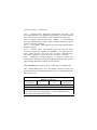
3.1.7. Operation. When liquid nerve or blister agents contact M8 paper,
a color change takes place. This color change is used to make an initial
assessment of the presence of liquid nerve or blister agent. Never use the
results from M8 paper as the sole indicator that liquid nerve or blister
agents are present.
GOLD
RED
GREEN
G-Series
H-Series
V-Series
Nerve
Blister
Nerve
If the paper turns red brown, it is an indication that a certain nerve (G)
agent is present. This positive indication is not represented on the color
comparison chart inside the cover.
Do not check M8 paper with a colored light, because you will not see
liquid chemical agent red spots.
3.1.8. Operational Use. M8 paper detects either through an active or
passive method.
3.1.8.1.
Active - Remove a sheet of M8 paper and dip the paper into the
liquid, or blot the area, to be tested. Do Not scrub or rub M8 paper on
suspected contaminated surfaces as false positives may result. Observe the
paper for color changes. Compare the color changes against those on the
inside booklet cover. Do Not touch paper to booklet.
3.1.8.2.
Passive - Remove a sheet of M8 paper. Secure the sheet to any
object in an area that would most likely receive contamination (building,
vehicle). Periodically check paper for color changes. Compare the color
changes against those on the inside booklet cover. Do Not touch paper to
booklet.
AFH 32-4014, Volume 3, 1 February 1998
31
3.1.9. Operational Limitations. M8 paper will function in snow, rain,
and sleet. However, if the M8 paper becomes saturated with water, false
color changes can occur. M8 paper reaction is immediate at temperatures
above 32°F. At temperatures below 32°F, reaction time may take up to two
minutes. The B1 dye that M8 paper is treated with will deteriorate rapidly
at temperatures above 125°F.
3.1.10. Decontamination. Discard as contaminated waste.
32
AFH 32-4014, Volume 3, 1 February 1998
3.2. M9 Chemical Agent Detector Paper
NSN 6665-01-049-8982
3.2.1. Purpose. The M9 paper will detect G and V Nerve agents and H
and L blister agents. M9 paper manually provides a visual image of liquid
chemical agent droplets. When worn on protective clothing or attached to
equipment, M9 paper provides one rapid assessment of detection.
3.2.2.
Technical Reference. T.O. 11H2-2-21
3.2.3.
Training Reference. RTP F1
3.2.4. General Description. M9 paper comes in a dispenser with one 30foot roll of 2-inch paper. The dispenser is 2.5 inches long, 3.5 inches wide
and 3.25 inches high. Each dispenser comes with a resealable plastic
storage bag.
3.2.5.
area.
Wartime User. All personnel in, or deploying to, a CB threat
3.2.6. Operating Range. 32°F to 125°F, with relative humidity between
0 - 99%.
AFH 32-4014, Volume 3, 1 February 1998
33
3.2.7. Operational Life. 1 year in temperate, tropic, and desert regions.
2 years, in frigid zones after removal from the shipping bag.
3.2.8. Shelf Life. The shelf life is six years from manufacturer’s date,
non-extendible.
3.2.9. Inspection. Inspection is a user responsibility. Inspect equipment
to include:
3.2.9.1.
Shipping bag and dispenser. If shipping bag is torn or open,
discard roll.
3.2.9.2.
Check for shelf life date that is stamped on the dispenser.
Discard if shelf life has expired.
3.2.9.3.
If dispenser is crushed, wet or cutting edge is missing, discard.
3.2.9.4.
Check paper for discoloration, tears, creases, or dirt. If paper
comes apart from backing, discard.
3.2.9.5.
Detector paper is serviceable unless the paper will not stick or
the paper is dirty or greasy.
Note: Do Not open shipping bag until ready for use; operational life of
detector paper will be shortened.
3.2.10. Operational Procedures. Tear open shipping bag and remove
dispenser and reusable storage bag. (Store M9 paper in plastic bag when not
in use.) Write the current date on dispenser. This date determines the
paper’s operational life. Remove cutting edge cover and discard. Start
paper through slot on dispenser with thumb or finger. Separate backing
from paper; backing should be exposed on one end of the dispenser and
paper on the other. Tear paper off about an inch from dispenser. Dispenser
is now ready for the next use.
3.2.11. Operational Use. M9 paper can be attached to protective
overgarment or equipment.
3.2.11.1.Overgarment: Attach paper to arm, wrist and ankle. Use the
buddy system to place paper on clothing. Configuration for wear is in T.O.
11H2-2-21. Overlap paper about an inch around each limb to prevent paper
34
AFH 32-4014, Volume 3, 1 February 1998
from coming loose. Paper must not be too tight around clothing or tears
will appear.
3.2.11.2. Equipment: Attach to vehicles, equipment, or supplies where it
can be seen. Attach detector paper on horizontal surfaces. For easy
removal, make a tab by folding adhesive side to adhesive side. When
attaching to equipment items, wrap detector paper around some part of the
equipment where it can attach adhesive side to adhesive side.
3.2.12. Paper Detection. M9 paper will turn different colors if liquid
agent comes in contact with paper. Color changes to M9 paper identify
agent presence, Not Agent Type. Positive liquid agents: pink, red, redbrown, red-purple. Blue, yellow, green, gray, or black spots are not from a
liquid chemical agent.
3.2.13. Operational Limitations. The following is a list of items that
cause false responses to M9 paper. Refer to T.O. 11H2-2-21 for complete
list.
3.2.13.1. Temperatures above 125°F.
3.2.13.2. Brake fluid, hydraulic fluid, gasoline, aircraft and automotive
grease.
3.2.13.3. DS-2 decontamination solutions.
3.2.13.4. Insect repellent.
3.2.14. Decontamination. Discard as contaminated waster.
AFH 32-4014, Volume 3, 1 February 1998
35
3.3. M256A1 Chemical Agent Detector Kit
NSN 6665-01-133-4964
3.3.1. Purpose. The M256A1 kit manually detects and classifies nerve,
blister, and blood agents in vapor or liquid form. The M256A1 samplerdetectors are capable of detecting and identifying vapors only. The M8
paper provided is to identify liquid agents.
3.3.2.
Technical Reference. T.O. 11H2-21-1
3.3.3.
Training Reference. RTP F2
3.3.4. General Description. The M256A1 kit contains 12 individually
wrapped sampler-detectors, one book of M8 detector paper, and a set of
operational instruction cards packaged in a plastic carrying case. The olive
drab plastic carrying case is 7 inches wide, 3 inches deep, and 5 inches
high.
3.3.5. Components.
3.3.5.1. Carrying case: Plastic shell, with a shoulder strap attached to
bottom of case.
36
AFH 32-4014, Volume 3, 1 February 1998
3.3.5.2. Sampler-detectors: 12 individually wrapped packets. The detectors
consist of: Blood and Nerve agent detector spots and ampoules with a
protective strip; Blister agent detector spots, ampoules, and a heating
assembly used in the testing process; Lewisite detecting tablet and rubbing
tabs.
3.3.5.3. M8 Paper: 1 booklet of chemically treated paper.
3.3.5.4. Operational instruction cards: 4 cards.
3.3.6. Wartime User. M256A1 kits are normally limited to those
personnel assigned to chemical detection duties such as reconnaissance and
shelter management teams. Prior to using the kit assume the proper MOPP
level.
3.3.7.
Operating Range. Between -25°F and 120°F.
3.3.8. Agents Detected.
Cyanogen Chloride
Mustard
Nitrogen Mustard
Distilled Mustard
Phosgene Oxime
Hydrogen Cyanide
Nerve Agents
Lewisite
CK
H
HN
HD
CX
AC
V and G Series
L
Blood
Blister
Blister
Blister
Blister
Blood
Nerve
Blister
3.3.9. Operational Limitations. The detector packages are a one-time
use item. If any of the following conditions exist, Do Not use: outdated
detector packages, discolored detector samples, open detector packages, or
water soaked samplers. Avoid direct sunlight on sampler when operating.
Avoid sampling in smoke and do not touch individual detector test spots.
3.3.10. Inspection: Inspect prior to use and annually. Verify the
manufacture’s date, stamped on cover of carrying case, prior to use.
AFH 32-4014, Volume 3, 1 February 1998
37
M256A1 kits are serviceable for 5 years from manufacture date. Complete
inspection procedures identified in T.O. 11H2-21-1.
3.3.11. Operational Use. Keep in mind the Cautions and Warnings
identified in the T.O. before using this kit. Complete procedures are
identified on the Operational Instruction Cards. Prior to using the kit
assume the proper MOPP level. Testing with the M256A1 takes about 20
minutes and is just one of a number of sources used to determine the
presence and extent of chemical contamination. When you conduct testing,
it is just as important to provide negative as well as positive results.
However, when checking for blood agents, a re-check is necessary if the
first results are positive. This is due to mercuric cyanide used in the blister
agent testing which could possibly be mistaken for hydrogen cyanide, a type
of blood agent. If the blood agent test is positive both times, call in a
positive result. When performing chemical testing, one ideal place to
monitor is around or above suspected areas of liquid agents. By using a box
or can, you can trap the vapors above the liquid for a better concentration.
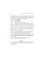
3.3.12. Operating the M256A1 Detector Kit. Breaking the ampoules
spreads the liquid contained in them over the separate testing spots. When
in contact with a chemical agent vapor, the liquid will react and change
colors on the test spot. This color change indicates a positive or negative
result. The lewisite tab works the same except it uses a tablet instead of
liquid. An initial rub mark is made on the tab for a color comparison,
against a second rub mark. The following indications summarize the test
results:
38
Lewisite
Blister
AFH 32-4014, Volume 3, 1 February 1998
After ten minutes of
exposure time Remember,
your first rub mark was a
tan color
Square test spot
(immediately after all
ampoules are broken)
Blood
Round test spot (after ten
minutes of exposure time)
Nerve
Star test spot (wait about
three minutes after
exposure)
1. Positive if the mark is
olive drab after rerub.
2. Negative if mark is tan
after rerub
3. Positive for H agent if
purple or blue.
4. Positive for CX agent if
red or purple.
5. Negative if colorless (if
temperature is high it may
be faint blue).
6. Positive if pink or blue.
7. Negative if yellow,
orange, tan, or colorless.
8. Positive if colorless or
peach.
9. Negative if blue.
3.3.13. Unusual Conditions. There are some special considerations based
on weather conditions. The procedures vary when using the kit in cold
weather as well as using the kit in a tropical climate.
3.3.13.1. Extend the wait times for the test spot by six minutes when
temperatures are between 32° and 50° degrees Fahrenheit or 0° and 10°
degrees Celsius.
3.3.13.2. Below 32 degree Fahrenheit (0°C) the reagent solution may
freeze. You must thaw it prior to use.
3.3.13.3. Retain a small amount of reagent after crushing ampoule marked
“3” in desert conditions, defined as high temperature and low humidity.
Rewet the nerve agent test spot after five minutes by squeezing the
remaining reagent from the ampoule “3” onto the nerve agent test spot.
3.3.13.4. For tropic conditions, a faint blue color may appear in
ABSENCE of blister agents H and HD. Otherwise, operation of the kit is
the same as it is for usual conditions. When judging the results, special
AFH 32-4014, Volume 3, 1 February 1998
39
care must be taken with the Lewisite rub marks. Since changes in color
may be vary slight, check the results with a second rub mark before making
a decision.
3.3.13.5. Protect the sampler-detector from rain or snow as much as
possible. Cover the detector with your body or use it under a roof or cover.
You could also use the same can or box that you used to trap vapors.
3.3.14. Decontamination. The carrying case is the only component that
can be decontaminated. All the internal components must be destroyed as
hazardous waste if contaminated. Decontaminate carrying case with
standard M258A1 or M295 kits. Follow procedures listed for use of the
decontaminating kits.
40
AFH 32-4014, Volume 3, 1 February 1998
CHAPTER 4 - DECONTAMINATION EQUIPMENT
4.1. M258A1 Personal Decontamination Kit
NSN 4230-01-101-3984
WARNING
The solutions are poisonous and caustic. Never allow solutions to contact
eyes, mouth, or wounds.
4.1.1. Purpose. The M258A1 kit provides the individual with a portable,
expedient, method of decontaminating the skin of liquid nerve and blister
agents.
4.1.2.
Technical Reference. T.O. 11D1-1-111
4.1.3.
Training Reference. RTP F5
4.1.4. General Description. The M258A1 kit contains six olive drab foil
packets in a plastic olive drab case. Three are numbered 1 and three are
numbered 2. The case is 2 inches by 4.25 inches in size. The lid is molded
to the case with a rubber o-ring. A nylon carrying strap with metal clip is
secured to the outside of the case.
AFH 32-4014, Volume 3, 1 February 1998
41
4.1.5.
area.
Wartime User. All personnel in, or deploying to, a CB threat
4.1.6.
Operating Ranges. Temperatures up to 110°F.
4.1.7. Storage Ranges. Temperatures up to 110°F. Store in clean, dry,
areas out of direct sunlight.
4.1.8. Operational Limitations. The packets are a one-time use item.
Do Not use if any of the following conditions exist: outdated or open
packets, seeping or swollen packets, or packets with dried residue. Packets
that have been subjected to direct sunlight or temperatures of 110°F should
not be used. Discard all defective packets as hazardous waste. Solutions in
packets are flammable; Do Not use around open flame.
4.1.9. Inspection. Inspection of M258A1 kit is the individual user’s
responsibility. Follow all procedures to prevent injuries.
4.1.9.1. Inspect the M258A1 prior to use.
4.1.9.2. Wear rubber gloves while inspecting kits.
4.1.9.3. Inspect for holes in packets.
4.1.9.4. Verify glass ampoules in packet 2 are not crushed.
4.1.9.5. Check if the case/packets is deformed, or packets have deteriorated.
4.1.9.6. Minor cracks in case, rubber O-ring missing, or nylon strap
missing do not constitute unserviceability.
4.1.10. Operational Use. When contamination is found or suspected on
skin, act immediately. If chemical protective clothing is not on put on your
mask and hood. Do not zip the hood. Do not pull the draw strings. Do not
fasten the shoulder straps. The M258A1 kit may be used to decontaminate
small equipment and the protective mask.
4.1.10.1. Follow the procedures below for skin decontamination:
4.1.10.1.1. Rubber gloves must be worn unless agent is on hand.
42
AFH 32-4014, Volume 3, 1 February 1998
4.1.10.1.2. Open lid, remove packet “1”.
4.1.10.1.3. Fold packet “1” in half at solid line, tear open at notches and
remove pad.
4.1.10.1.4. Unfold pad fully, wipe skin for 1 minute, discard pad.
4.1.10.1.5. Remove packet “2”, crush glass ampoules inside packet “2”.
4.1.10.1.6. Fold packet ”2” in half, tear open at notches, remove pad
letting screen fall.
4.1.10.1.7. Unfold the pad fully, wipe skin for 2-3 minutes, discard pad.
4.1.10.2.Follow these procedures if you have or suspect contamination on
your face:
4.1.10.2.1. Open lid, remove packet “1”.
4.1.10.2.2. Fold packet “1” in half at solid line, tear open at notches and
remove pad.
4.1.10.2.3. Unfold pad fully, wipe skin for 1 minute, discard pad.
4.1.10.2.4. Using pad “1”, wipe your hands.
4.1.10.2.5. Take a deep breadth and hold it, close your eyes, lift the mask
from the chin only far enough to get your hand inside. Quickly wipe the
lower part of the face and interior surfaces of the mask which contact the
skin.
4.1.10.2.6. Don mask, open eyes, and resume normal breathing.
4.1.10.2.7. Using the same “1” pad, wipe neck and ears.
4.1.10.2.8. Remove packet “2”, crush glass ampoules inside packet “2”.
4.1.10.2.9. Fold packet ”2” in half, tear open at notches, remove pad
letting screen fall.
4.1.10.2.10. Unfold the pad fully, Using pad “2”, wipe your hands.
4.1.10.2.11. Take a deep breadth and hold it, close your eyes, lift the mask
from the chin only far enough to get your hand inside. Quickly wipe the
lower part of the face and interior surfaces of the mask which contact the
skin.
4.1.10.2.12. Don mask, open eyes, and resume normal breathing.
4.1.10.2.13. Using the same “2” pad, wipe neck and ears.
AFH 32-4014, Volume 3, 1 February 1998
43
WARNING
Some skin reaction (reddening, itching) may result from the
decontamination process. The treated skin area should be washed with soap
and water as soon as practical after use.
4.1.11. Decontamination. The carrying case is the only component that
could require decontamination. If contaminated, destroy all internal
components as hazardous waste. Decontaminate carrying case with another
M28A1 or M291 kit.
Follow procedures listed for use of the
decontaminating kits.
4.1.12. Special Note. The M258A1 kit is not for training. A training kit
(M58A1) is available for training, NSN 6910-01-101-1768. Refill packets
are also available, NSN 6910-01-113-2434.
44
AFH 32-4014, Volume 3, 1 February 1998
4.2. M291 Skin Decontaminating Kit
NSN 6850-01-276-1905
4.2.1. Purpose. The M291 Skin Decontaminating Kit provides the user
capability to completely decontaminate through physical removal,
absorption, and neutralization of chemical agents on the skin.
4.2.2.
Technical Reference. T.O. 11D1-1-131
4.2.3.
Training Reference. RTP F7
4.2.4. General Description. The M291 kit consists of 6 individual
decon packets in a wallet sized carrying pouch. Each packet contains an
applicator pad filled with decon powder. Each kit will do three complete
skin decontaminations.
4.2.5.
area.
Wartime User. All personnel in, or deploying to, a CB threat
4.2.6.
Operating Ranges. -50°F to 120°F.
4.2.7.
Storage Ranges. -60°F to 160°F.
AFH 32-4014, Volume 3, 1 February 1998
45
4.2.8. Inspection. The user must do the following inspection prior to
use:
4.2.8.1. Inspect kit for loose black powder. If no loose powder is present,
the kit is serviceable.
4.2.8.2. If powder is detected, inspect each packet for leaks.
4.2.8.3. Discard all leaking packets.
4.2.8.4. Replace bad packets with new ones. Six total packets make a
complete kit.
Note: The M291 kit is for external use only. Powder may be slightly
irritating to skin or eyes. Keep powder out of eyes, cuts and wounds.
4.2.9. Operational Use. When contamination is found on skin, act
immediately. Put on your mask and hood. Do not zip the hood. Do not
pull the draw strings. Do not fasten the shoulder straps. Seek overhead
cover or use a poncho for protection against further contamination.
4.2.10. Skin Decontamination. Follow these procedures:
4.2.10.1.
Remove one packet, tear open at notch.
4.2.10.2.
Remove applicator pad from packet.
4.2.10.3.
Unfold applicator pad and slip gloved hand into handle.
4.2.10.4.
Thoroughly scrub exposed skin until completely covered
with black powder.
4.2.10.5.
If gross contamination exists, two pads may be required.
4.2.10.6.
Scrub gloved hand with powder.
4.2.10.7.
Place protective clothing on exposed skin.
4.2.10.8.
Discard contaminated pads as hazardous waste.
4.2.10.9.
Remove powder with soap and water when conditions
permit.
4.2.11. Face Decontamination. If contamination is suspected on face or
neck, complete procedures for removal are identified in T.O. 11D1-1-131.
Contamination around face or eyes requires detailed removal procedures.
46
AFH 32-4014, Volume 3, 1 February 1998
Some assistance may be required to remove the contamination. Buddy care
or buddy assistance may be needed. Follow these steps:
4.2.11.1. Hold your breath, close your eyes, grasp your mask beneath the
chin, and pull the hood and mask away from your chin enough to allow one
hand between the mask and your face. Hold the mask in this position while
accomplishing the remaining steps.
4.2.11.2. Starting at the front of one of your ears, scrub the pad across
your face to the corner of your nose. Scrub extra strokes at the corner of
your nose. Then scrub across your nose, to include the tip, to the other
corner of your nose. Again, scrub extra strokes at the corner of your nose.
Then scrub across your face to the front of your other ear.
4.2.11.3. Scrub across your cheek to the corner of your mouth. Keep your
mouth closed. Make extra strokes at the corner of your mouth. Then scrub
across your closed mouth to the center of your upper lip. Scrub extra
strokes above your upper lip. Continue to scrub across your closed mouth to
the other corner of your mouth. Again, scrub extra strokes at the corner of
your mouth.
4.2.11.4. Finish up by scrubbing across your cheek to the end of your
jawbone.
4.2.11.5. Scrub across and under your jaw to your chin, cupping the chin.
At the center of your chin, scrub extra strokes. Continue to scrub across
and under your jaw to the end of your jawbone.
4.2.11.6. Turn your hand out and quickly wipe the inside of your mask
that touches your face.
4.2.11.7. Discard the applicator pad and immediately seal, clear, and
check your mask.
4.2.11.8. Remove the second skin decon packet from its carrying pouch.
At the notch, tear open quickly. Remove the applicator from its packet and
discard the empty packet. Unfold the applicator pad and slip your finger(s)
into the handle.
4.2.11.9. Without breaking the seal between your face and mask,
thoroughly scrub your neck and ears until they are completely covered with
black powder.
AFH 32-4014, Volume 3, 1 February 1998
47
4.2.11.10. Redo your hands until they are completely covered with black
powder.
4.2.11.11. Discard the applicator pad and, if you are not wearing protective
gloves, put them on at this time. Fasten your hood.
4.2.11.12. Remove the black powder with soap and water when conditions
permit.
4.2.10. Decontamination. Discard carrying pouch and decontaminate
remaining kits with M295 or other M291 kits.
48
AFH 32-4014, Volume 3, 1 February 1998
4.3. M295 Individual Equipment Decontamination Kit
NSN 6850-01-357-8456
4.3.1. Purpose. The M295 Kit allows the individual to decontaminate
their equipment through physical removal and absorption of chemical
agents.
4.3.2.
Technical Reference. Technical Manual TM-3-4230-235-10
4.3.3.
Training Reference. RTP F9
4.3.4. General Description. Each M295 Kit consists of a carrying pouch
containing four individual decon packets. Each packet contains a decon
mitt filled with decon powder. The packet is designed to fit comfortably in
the pocket of the ground crew ensemble. Each individual mitt is comprised
of absorbent resin contained within a nonwoven polyester material.
4.3.5. Wartime User. All personnel in, or deploying to, a CB threat
area. Contamination Control Teams (CCT) and Contamination Control
Area (CCA) monitors may have additional decontamination requirements.
AFH 32-4014, Volume 3, 1 February 1998
4.3.6.
Operating Ranges. -25°F to 180°F
4.3.7.
Storage Ranges. -60°F to 180°F
49
4.3.8. Inspection. Inspect kit for loose black decon powder. If no
powder is detected, the kit is operational. If powder is detected, inspect
each packet for leaks. Discard all leaking packets. A complete kit consists
of 4 serviceable packets.
4.3.9. Operational Use. This kit is intended for equipment and may be
slightly irritating if used on the skin. To use, follow these procedures in
sequence:
4.3.9.1. Remove decontamination packet.
4.3.9.2. Tear open packet.
4.3.9.3. Remove decon mitt.
4.3.9.4. Discard empty packet.
4.3.9.5. Unfold decontamination mitt.
4.3.9.6. Grasp green (non pad) side of decontamination mitt with one
gloved hand, pat the other gloved hand until completely covered with
powder.
4.3.9.7. Insert decontaminated gloved hand into mitt, tighten wristband on
glove.
4.3.9.8. Decontaminate individual equipment by rubbing with mitt.
4.3.9.9. Decontaminate gloved hand that was holding equipment.
4.3.9.10. Discard mitt.
4.3.9.11. If more contamination is present, use another mitt following
procedures above.
4.3.9.12. All personal equipment can be decontaminated with the mitt.
4.3.10. Operational Limitations.
The contaminated mitt must be
destroyed as chemical hazardous waste.
50
AFH 32-4014, Volume 3, 1 February 1998
4.4. M17 Decontaminating Apparatus
NSN: 4230-01-251-8702
NSN: 4230-01-346-1778 (M17 A2)
WARNING
The M17 uses a variety of fuels and produces water pressure in excess of
100psi. To prevent death, injury, fire or explosion, follow all rules
established in T.O. 11D1-3-9-1.
4.4.1. Purpose. The M17 Decontamination Apparatus provides the user
with a portable decontaminating capability. Decontamination at an airbase
is essential to sustain operations once an airbase has been contaminated.
Fixed site decontamination is not supportable or practical once chemical or
biological agents are introduced on an airbase.
4.4.2. Technical Reference. T.O. 11D1-3-9-1, 11D1-3-9-2, and 11D13-9-1CL-1
4.4.3.
Training Reference. RTP F8
AFH 32-4014, Volume 3, 1 February 1998
51
4.4.4. General Description. The M17 decontamination apparatus is
comprised of seven major component systems: engine, engine fuel system,
electronic control system, air system, heater system, heater fuel system and
water system. These systems provide a supply of pressurized, temperature
controlled water. The apparatus weighs 360 lbs, is 40.2 inches long, 23.2
inches in width and is 33.9 inches in height.
4.4.5. Wartime User. The M17 requires special training to operate. Due
to its complexity of parts, handling requirements, and special operating
procedures, the M17 should be used only by personnel trained in its
operation. CCT team members are the primary users of this equipment.
4.4.6. Components. The following is a list of major components:
4.4.6.1.Engine: Single cylinder, two cycle, 197 cc, 7.3 hp, air cooled. Fuel
mixture: 2 cycle oil and unleaded gas, 1qt of oil to 5 gallons of gas.
4.4.6.2.Heater: Convection, jet fired, igniter plug ignition, 700,000 BTU.
Runs on leaded or unleaded gasoline and will run on diesel (DF2), jet fuel
(JP4), or kerosene.
4.4.7. Accessory Kit. Box weighs 143 lbs, 41.8 inches long, 20.5 inches
wide, 15.4 inches in height.
4.4.7.1. Suction hose, 33 feet long with quick disconnect.
4.4.7.2. Branch hose, 3 feet long with quick disconnect.
4.4.7.3. Pressure hoses, 50 feet in length quick disconnect.
4.4.7.4. Shower sets (2 each), 3-section with 6 jets each, 8 feet in length
with quick disconnect.
4.4.7.5. Spray wands, 3 foot single sections, trigger actuator with quick
disconnect.
4.4.7.6. Injector, 80/20 siphon, with cam coupling.
4.4.7.7. Water tank, 1580 gallon, collapsible, self-erecting rubberizednylon, weight 70 lbs (empty) and 5.8 feet in height (full). Stored separately.
4.4.8. Power Requirements. No external power is required to operate
this system. Only a source of water and fuel is needed.
52
AFH 32-4014, Volume 3, 1 February 1998
4.4.9. Operating Ranges. Two operating ranges for operation:
4.4.9.1. Usual conditions: Above 32°F, refer to Section III of T.O.
4.4.9.2. Unusual conditions: Below 32°F, refer to section IV of T.O.
4.4.10. Operational Limitations.
The M17 will operate in all
environments; however, extra care of the M17 components must be properly
maintained in weather below 32° to prevent failure. The M17 is limited
only by its water and fuel supply. The unit is heavy and moving it requires
at least four people.
4.4.11. Inspection. The inspection of the M17 requires Preventive
Maintenance Checks and Services (PMCS). These procedures are described
in detail in section II of T.O. 11D1-3-9-1, which gives user actions for
before, during, and after operations. The T.O. outlines unit maintenance
and specifies the semi-annual, annual, biennial, and hourly PMCS actions.
4.4.12. Decontamination.
The M17 and its components can be
decontaminated using spray wands.
Mixtures and pressures for
decontamination are identified in the T.O.
AFH 32-4014, Volume 3, 1 February 1998
53
CHAPTER 5 - SPECIALIZED DETECTION EQUIPMENT
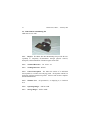
5.1. Automatic Liquid Agent Detector (ALAD)
NSN 6665-01-314-2086
AN/PSR-2 System and Auxiliary Alarms
5.1.1. Purpose. The ALAD provides the user with an automatic liquid
chemical agent detector. ALADs are intended for use with existing vapor
detectors.
5.1.2.
Technical Reference. T.O. 11H2-22-1
5.1.3.
Training Reference. RTP F10
5.1.4. General Description. The AN/PSR-2 system is a self-contained,
battery powered, portable liquid chemical agent detector. It will detect 200
micron-size droplets or larger of liquid GD, VX, Mustard, or Lewisite
chemical agents on the sensor within 60 seconds.
5.1.5. Components. The AN/PSR-2 Detector unit assembly consists of
one detector and five sensors. The detector is 12.62 inches long, 8.5 inches
54
AFH 32-4014, Volume 3, 1 February 1998
wide and weighs 9 pounds without battery. The auxiliary alarm is 15
inches long, 12 inches wide and weighs 23 pounds. The ALAD is
compatible with the M42A1 Auxiliary Alarm. Refer to Army technical
manual 3-665-302-34 for the care and use of the M42A1 alarm. The
detector unit has the following controls and features:
5.1.5.1. Sensor Pins: mate detector unit to chemical agent sensor.
5.1.5.2. Horn: gives a 75 decibel sound alarm (at 3 feet) in all directions
from unit.
5.1.5.3. Power Switch: applies AC or DC power to detector unit.
5.1.5.4. Lamp: gives a flashing light alarm that can be seen 25 feet from
unit.
5.1.5.5. Signal Post: allows connection to external alarms with field wire.
5.1.5.6. Sensor Mounting Plate: allows mounting of sensor and contains
sensor heater for cold weather operations.
5.1.5.7. Sensor Holder Clamp: assists in correct positioning of sensor.
5.1.5.8. Horn Enable/Off Switch: allows operator to enable/disable
detector unit horn.
5.1.5.9. Lamp Enable/Off Switch: allows operator to enable/disable
detector unit lamp.
5.1.5.10. Alarm/BIT Instructions: provides operator with signal codes and
instructions for alarm activation and unit Built-In-Test.
5.1.6. Theory of Operation. The ALAD theory of operation is divided
into five circuit groups: power, controller board, sensor, internal alarms,
and external alarms.
5.1.6.1. The ALAD operates on battery or AC power.
A
nonrechargeable BA-5588/U lithium sulfur dioxide battery provides DC
power to the ALAD. It provides power for at least 30 days. A power switch
controls both AC and DC power to the detector unit. When the power is set
to [ON] the unit starts a self-diagnostic test.
5.1.6.2. A microprocessor controls all functions of the detector unit. The
detector unit also has built-in protection from electro-magnetic pulses
(EMP).
AFH 32-4014, Volume 3, 1 February 1998
55
5.1.6.3. The sensor is a one time use item. When the sensor is placed on
the mounting plate, an electrical current is passed from contact to contact
through the metallic paint on the grooved surface. If attached to AC power,
the system will heat the sensor plate to 70oF if needed. (This occurs when
the outside temperature is less than 70oF.) When a 200 micron droplet or
more of chemical agent falls on the sensor, it causes the metallic paint in
the groove to swell. When the paint swells, the resistance of the sensor
changes, and the detector unit recognizes that a chemical agent is present.
This sends a signal to the alarm. It detects GD, VX, Mustard, Lewisite, and
simulant DEM type chemical agents. The sensor is not sensitive to most
flight-line chemicals.
5.1.6.4. The system has an internal horn and lamp alarm. The horn
sounds either, when chemicals are present, or when signals faults occur in
the system. The lamp alarm provides continuous flashing light when an
alarm signal is received from the ALAD. A low battery LED provides
continuous warning light when battery voltage is low. The test push-button
provides self-test to ensure the horn and lamp are working.
5.1.6.5. The unit is capable of operating with remote auxiliary alarms.
Two different auxiliary alarms can be connected to the detector unit, the
BZ-90/PSR-2 and the chemical agent automatic alarm unit ABCA-M42.
When a chemical agent is detected it sends a signal to these alarms. The
BZ-90/PSR-2, commonly referred to as the BZ-90 alarm comes with the
ALAD. The ABCA-M42, commonly referred to as the M42 is compatible
with the ALAD.
5.1.6.6. External alarms may be connected with field wire up to a
distance of 1000 feet from the detector unit assembly. Signal posts on the
system provides quick connections between the ALAD detector unit and
auxiliary alarms.
5.1.7. Wartime User. The ALAD can be operated by anyone trained in
the use of chemical agent detectors. NBC recon and shelter teams are the
primary users.
56
AFH 32-4014, Volume 3, 1 February 1998
5.1.8. Power Requirements. The ALAD will operate on both AC/DC
power.
5.1.8.1. AC: 110/220 VAC, 60/50 Hz, single phase.
5.1.8.2. DC: Non-rechargeable lithium sulfur dioxide battery. BA5588/U
5.1.8.3. Battery Service Life: 30 days.
5.1.8.4. The auxiliary alarm will only operate on DC power.
5.1.8.5. DC: Two rechargeable, sealed, lead-acid batteries, GC 1245-1.
5.1.8.6. Battery Service Life: 100 to 1000 recharges.
5.1.8.7. Recharge Time: 12 to 16 hours.
5.1.9. Operating Ranges. ALAD Operation: -30 to 125°F - Storage 75 to 165°F. Auxiliary Alarm Operation: -30 to 125°F Storage -75 to
165°F
5.1.10. Sensor Disc Service Life. 30 days after removal from package if
not contaminated. The Shelf life is 5 years. Expired sensor discs can be
used for training. If they are not available, simulated reading can be
obtained by making an electrical connection between the inner and outer
posts on the ALAD.
5.1.11. Sensor Disc Operating Ranges. -30 to 125°F.
5.1.12. Sensor Disc Storage Ranges. -30 to 160°F.
5.1.13. Special Tools. No special tools are required.
5.1.14. Operational Limitations. The sensor discs are a one-time use
only item. After removal from packaging, the discs are good for 30 days.
The sensor must be replaced if dirt or debris is visible on the sensor surface.
5.1.15. Inspection/Use. Refer to T.O. 11H2-22-1 before inspection and
use.
AFH 32-4014, Volume 3, 1 February 1998
57
5.1.16. Operations and Employment. Prior to operation, the ALAD
detector unit assembly must be setup. This includes an inspection of the
unit, battery installation, sensor card installation, and connection to AC
power.
5.1.16.1. After you prepare the unit for operations, the Built-In-Test
(BIT) will self-check the internal electronic circuitry, sensor, and battery as
soon as the power switch is set turned [ON]. The lamp will light during BIT
and, when the lamp goes off, all testing is complete and the unit is ready.
5.1.16.2. Faulty units will indicate failure signals. Corrective actions for
the following failure signals are listed in the technical order:
bad unit: three beeps
bad sensor: 2 beeps
bad battery: 1 beep
lamp on
lamp on
lamp off
5.1.16.3. Prior to operation, the remote alarms must be prepared for
operation. This includes an inspection of the unit, installation of the
batteries, and a test of the unit.
5.1.16.4. Employment. When both the detector unit assembly and the
auxiliary alarm are prepared for use, they may be deployed into the field.
The detector unit should be placed on a level surface free from overhead
cover. The auxiliary alarm should also be placed on a level or stable surface
and can be used both outside or indoors.
5.1.17. Calibration. None required.
5.1.18. Decontamination. The ALAD system is painted with a Chemical
Agent Resistant Coating (CARC). All components of the system except the
sensor disc can be cleaned with standard decontaminants (M295, soap and
water).
58
AFH 32-4014, Volume 3, 1 February 1998
AFH 32-4014, Volume 3, 1 February 1998
59
5.2. Chemical Agent Monitor (CAM)
NSN 6665-01-199-4153
WARNING
RADIATION HAZARD
The CAM contains a beta radiation source. The source is a plated cylinder
of 10 millicuries of Nickel-63 radiation. Do Not attempt to open the CAM.
5.2.1. Purpose. The CAM is a hand held point monitor capable of
detecting and identifying nerve and mustard agent vapors, giving a rough
indication of concentration within 1 minute of agent exposure. CAMs are
intended for use to search out clean areas, and to identify contaminated
personnel, equipment, aircraft, vehicles, buildings and terrain. CAMs will
determine the effectiveness of decontamination and can be used in collective
protection shelters.
5.2.2.
Technical Reference. T.O. 11H2-20-1
5.2.3.
Training Reference. RTP F19
60
AFH 32-4014, Volume 3, 1 February 1998
5.2.4. General Description. CAMs utilize Ion Mobility Spectrometry
(IMS) technology to detect GA, GB, GD, VX, HN, and L. The CAM
weighs a little over three pounds with battery and is 15.5 inches in length.
5.2.5. Wartime User. The CAM can be operated by anyone trained in
the use of chemical agent detectors. NBC recon, CCA, and shelter teams
are the primary users.
5.2.6. Components.
The basic CAM comes with the following
components: carrying case assembly, CAM, carrying harness assembly,
filtered nozzle package assembly, spare battery, large handle strap, small
handle strap, confidence sample, spare nozzle protective cap assembly,
nozzle protective cap assembly, nozzle assembly, battery, battery cap
assembly and environmental cap. Available auxiliary equipment includes an
optional battery used for operational check-out and training, and a buzzer to
provide audible alarm when the detector reads three bars or more.
5.2.7. Power Requirements. The CAM uses one internal 6-volt lithium
sulfur dioxide battery (BA-5800/U). Do Not immerse battery in water or
decontamination solution, crush, or burn batteries. Do Not attempt to
recharge batteries. Batteries are considered hazardous waste; dispose of
IAW local hazardous waste procedures. Battery life varies with frequency
of use and temperature. The following are benchmarks for temperature
versus battery life:
113°F
68°F
32°F
-13°F
(45°C)
(20°C)
(0°C)
(-25°C)
5.2.1.
Operating Ranges. -13 to 113°F.
5.2.2.
Storage Ranges. -67 to 158°F.
14 hours
12 hours
10 hours
2 hours
AFH 32-4014, Volume 3, 1 February 1998
61
5.2.3. Operational Limitations. The CAM is a monitor, not a detector,
and can become contaminated or overloaded (saturated) if not used
properly. The CAM can only detect vapors at the inlet nozzle. It will not
give the vapor hazard over an area from a single point.
5.2.4. Inspection. The inspection of the CAM requires Preventive
Maintenance Checks and Services (PMCS). These procedures are described
in detail in T.O. 11H2-20-1.
5.2.5. Decontamination. Do Not decontaminate the CAM or its
accessories with the M258A1 Decontamination kits. False readings may
occur and render the CAM inoperative. To decontaminate, discard the
filtered nozzle standoff. Turn the CAM off. Wipe the nozzle assembly,
using a cloth dampened with water only. Install the nozzle protective cap
on the CAM nozzle. Turn the CAM on. The display should clear within 15
minutes. If the CAM does not clear within 15 minutes, repeat procedures.
If problems still exist, turn CAM in for replacement.
62
AFH 32-4014, Volume 3, 1 February 1998
5.3. M8A1 Chemical Agent Alarm
NSN 6665-01-105-5623
WARNING
RADIATION HAZARD
The cell module of the M43A1 Detector contains a radioactive source:
Americium-241. The cell module is potentially dangerous if broken. Do
Not attempt to remove the cell or pump modules.
5.3.1. Purpose. The M8A1 Detector provides an automatic detection
capability for nerve agent vapors (GA, GB, GD and VX). The M8A1 can
be used at fixed sites, hand carried, carried on a backpack, or mounted on a
vehicle.
5.3.2.
Technical Reference. T.O. 11H2-17-1
5.3.3.
Training Reference. RTP F3
AFH 32-4014, Volume 3, 1 February 1998
63
5.3.4. General Description.
The M8A1 alarm consists of two
components: an M43A1 detector and an M42 Alarm unit. Major
components are listed below separately.
5.3.5. Wartime User. The M8A1 can be operated by anyone trained in
the use of chemical agent detectors. NBC recon, CCA, and shelter teams
are the primary users.
5.3.6. Components. The following components make up the M8A1
system. The system provides the user the option of deciding what
components are needed. They are:
5.3.6.1. M43A1 Detector: Automatically detects nerve agent vapors. It
will alarm and send a signal to a connected M42 Alarm. (weight 7 pounds,
length 7 inches, width 7.75 inches, height 10.75 inches)
Power requirements.
18 volt DC to 36 volt DC
BA3517/U Battery or
BB501/U Battery (M253 Winterization kit) or
M10 Power supply (115/220 volt AC, 50-400 Hz) or
Vehicle Power
5.3.6.2. M42 Alarm Unit: Provides a warning light and horn at a remote
location (up to 400 meters away) when the M43A1 detects nerve agent
vapors. (weight 4 pounds, length 8 inches, width 6 inches, height 2.25
inches)
Power requirements
Battery, dry, 1.5 volt, BA3030/U (4 each)
5.3.6.3. M10A1 Power Supply: Converts power from an AC source to
DC power for the M43A1 Detector. It accepts 115 or 220 VAC, 50 to 400
HZ and switches automatically to the standby battery if output drops below
64
AFH 32-4014, Volume 3, 1 February 1998
18 VDC. The M10A1 attaches directly to the bottom of the M43A1
Detector. (weight 6.5 pounds, length 7.5 inches, width 6.5 inches, height
3.2 inches)
5.3.6.4. M10 Power Supply: Provides DC power to the M43A1 detector
by converting 115/220 volt AC, 50-400 Hz power. (weight 18 pounds,
length 12 inches, width 6 inches, height 7 inches)
5.3.6.5. BA3517/U Battery: Supplies 36 volt DC power to M43A1
Detector weight (7.5 pounds, length 6.3 inches, width 7.7 inches, height 5
inches). Non-rechargeable
5.3.6.6. M273 Maintenance Kit: Contains 10 air filters and 10 test
paddles.
5.3.6.7. Probe Assembly: Contains 5 probes, 5 rubber bands, and 5
instruction cards. Enables the M43A1 detector to monitor equipment,
vehicles and personnel for vapor contamination.
5.3.7.
Operating Ranges. -40°F to 120°F, 3 to 99% relative humidity
5.3.8. Operational Limitations. The M8A1 is limited by both battery
power life and airfield interference. Refer to T.O. 11H2-17-1 for guidance.
5.3.9. M8A1 Assembly And Operation. The M8A1, used as a fixed
emplacement alarm system, can be assembled and used in any of three
power configurations and with or without an M42 alarm connected. The
three power configurations are:
5.3.9.1. M43A1 Detector with the BA3517/U Battery.
5.3.9.2. M43A1 Detector with the M10A1 Power Supply.
5.3.9.3. M43A1 Detector with both the BA3517/U Battery and M10A1
Power Supply.
WARNING.
Do not operate M43A1 detector indoors unless an outlet filter is installed.
Do not operate inside moving vehicle with or without filter. Radiation
exposure could occur.
AFH 32-4014, Volume 3, 1 February 1998
65
CAUTION
To prevent damage to the electronics component, do not use power sources
above 125 VAC or 230 VAC when operating the power supply.
5.3.10. Operating The M8A1 In Cold Weather. When the outside
temperature reaches 20°F or below, the M8A1 must be operated in a cold
weather configuration.
To help accomplish this task, an M253
Winterization Kit is available. The M253 Winterization Kit provides DC
power when temperature ranges from 20°F to -40°F. The kit contains two
BB501/U rechargeable batteries and one M168 cable.
5.3.11. M8A1 Malfunctions. The M8A1 may malfunction. You may
correct some of the common malfunctions that can include:
M43A1 DETECTOR MALFUNCTIONS ARE:
Doesn't register in green band. Low
airflow can be caused by a clogged
filter. Make sure that the air filter
plug is screwed tight, outlet cap
removed, and air outlet clean.
Detector
Doesn't register in black area with
battery test and reset press button
depressed. This may be a problem
with the power connectors.
Detector meter doesn't
Install flowmeter and adapter in air
register in green band.
inlet. With the detector operating,
wait 5 to 60 minutes and read detector
meter. If it does not read in the green
band send the unit to maintenance.
Detector meter doesn't
Attach the M253 Winterization Kit
register in green area when
and test the system.
temperature is below 20°F.
Flowmeter
æ
æ
æ
æ
66
M42 alarm
M43A1 detector doesn’t
register in the black area
with battery test and reset
press button depressed.
AFH 32-4014, Volume 3, 1 February 1998
æ
æ
Does not sound during tests or when
nerve agent is detected by M43A1
detector. Check the batteries, power
connections, and wires to the M43A1.
Check the fuses and power
connectors.
5.3.12. Employment of M43A1s. M43A1 Detectors may be employed at
widespread indoor and outdoor locations around the installation in a DICE
5 pattern. The M10A1 Power Supply should be used whenever possible.
5.3.13. Employment of M42s. M42 Alarms should be installed primarily
in work centers (preferably ones with collective protection) to remotely
monitor the M43A1s. NOTE: The M42 alarm may not be heard in high
noise areas. Also, the M43A1 may falsely alert to some aftershaves and
smokes.
5.3.14. Inspection/Use/Calibration/Decontamination.
Due to the
complexity of the M8A1 system, detailed procedures must be followed to
use this system. Because of the radioactive source inside the unit, a "wipe
test" must also be performed to ensure that the units are not leaking any
radioactive sources. Technical Order procedures in all phases of use,
maintenance, calibration and decontamination must be followed to prevent
detector system failure. USAF M8A1s do not require calibration.
AFH 32-4014, Volume 3, 1 February 1998
67
5.4. M90 Chemical Agent Detector
NSN 6665-01-408-5108
WARNING
RADIATION HAZARD
The M90 utilizes a small sealed radioactive source, AM-241, as a part of
the detection system. The unauthorized repair or disassembly of the M90
may result in Alpha radiation contamination and exposure.
5.4.1. Purpose. The M90 Detector provides the Air Force with standalone nerve and blister agent detection. The M90 will detect nerve and
blister agent vapors at levels that prevent over exposure to personnel. The
M90 can be networked to provide airfield chemical detection and warning,
as well as a shelter monitoring device. The M90 is a multi-application
instrument which is capable of operating as a point detector to provide early
warning of approaching toxic chemicals or as a chemical agent monitor to
identify and monitor personnel, vehicles, and equipment for contamination.
5.4.2. Technical Reference. M90 Users Manual, no technical order
assigned.
68
5.4.3.
AFH 32-4014, Volume 3, 1 February 1998
Training Reference. RTP F4
5.4.4. General Description. The M90 uses Ion Mobility Spectrometry
(IMS) to determine the presence of toxic vapors. The detector is portable or
can be vehicle mounted. Weight with battery is 15 pounds. Dimensions are
length 11 inches x width 4 inches x height 11 inches.
5.4.5. Wartime User. The M90 can be operated by anyone trained in the
use of chemical agent detectors. NBC recon, CCA, and shelter teams are
the primary users.
5.4.6. Components. The M90 does not come in a kit. Various
components are available to allow different uses in the field. Following is a
complete list of all components:
M90 detector unit
M90-RH2 Remote alarm unit
M90-BC Battery charger
M90-IT2 Inlet tube
M90-CC Communications
cable
M90-CB Carrying bag
Battery case
M90-MP1 Main power supply
M90-VP1 Vehicle power supply
M90-FT/S Filter tool
Sample kit containing 2 stimulants,
nerve and blister
5.4.7. Power Requirements. The M90 is capable of being powered by
several different batteries and power supplies. The batteries must be
capable of providing at least 11 volts of power. Different power
requirements are based on intended usage. The following list describes the
various requirements:
5.4.7.1. M90-NB NiCd rechargeable D-cell battery, comes standard with
detector; 8 hours use.
5.4.7.2. M90-LB Lithium non-rechargeable battery, BA-5598/U; 16
hours use.
AFH 32-4014, Volume 3, 1 February 1998
5.4.7.3.
hours use.
5.4.7.4.
5.4.7.5.
DC.
5.4.7.6.
69
M90-MB Magnesium non-rechargeable battery, BA-4386; 16
M90-MP1 Main power supply, 115/240 volt AC, 60Hz.
M90-VP1 Vehicle power supply, AC/DC converter 10-32 volt
M90-VP2 Vehicle power supply, 24-34 volt DC converter.
5.4.8. Battery Life. This is dependent on climatic conditions. Cold
temperatures degrade battery life and decrease battery voltage. At room
temperature, the NiCd battery will last about 8 hours. Operational tests
show a realistic battery life of about 4-6 hours for NiCd batteries in the
field.
5.4.9. Battery Recharge. The M90-BC battery charger only recharges
one NiCd battery pack at a time. The battery charger requires 6 hours to
charge one battery pack. The NiCd batteries will only take a charge when
temperatures are between 32°F and 104°F.
5.4.10. Operating Ranges. M90 will operate in temperatures between 22°F and 131°F with 10 to 95% humidity.
5.4.11. Care and Use. The M90 has a specific set of operational
procedures to make the unit ready for use. Complete details on these
procedures are outlined in the “M90 Users Manual”. Failure to adhere to
these procedures will render this device inoperable.
5.4.12. Inspection. Refer to chapter 2 of the M90 Users Manual for
complete details. Preventive maintenance checks and services include
preparation for operation, starting, testing the detector, alarms, operations
under unusual conditions, shutdown procedures, and troubleshooting. The
operator must perform the following checks to insure proper operation of
the M90 and avoid failure of alarms:
70
AFH 32-4014, Volume 3, 1 February 1998
5.4.12.1. Inspect both the air inlet and outlet are open and free from
blockage.
5.4.12.2. Check that the internal air filter and the external pump port caps
are tightly closed.
5.4.12.3. Visually inspect that a serviceable battery or power supply is
connected.
5.4.12.4. The detector sensor should be tested with the stimulant after
every startup, or if in continuous operation, once a month. The testing is
done with the simulant tube once startup is completed. The simulant tub
contains nerve agent simulant. The simulant needs to be warmed to at least
+50 F(+10 C) to react correctly. Ensure testing is conducted away from
strong wind or drafts.
5.4.13. Concept of Employment. The M90 should be employed around
an air base in a DICE 5 pattern for early detection and warning of chemical
agent vapors.
5.4.13.1. Because it is a point source detector, every effort must be made
to place a sufficient number of detectors upwind of the air base and missioncritical areas.
5.4.13.2. Place M90 units no closer than 500 meters apart within the
confines of the base. This placement can change due to the prevailing
winds, likely attack routes, threat assessment, proximity to major lines of
travel, work-area noise levels, etc.
5.4.13.3. Place the M90 units no closer than 25 feet from any major
structure to ensure maximum exposure to prevailing winds and limit
interference caused by buildings.
5.4.13.4. Be sure to avoid place the M90 around smoke, jet fuel vapors,
and diesel exhaust. The M90 has shown sensitivity to these interferents and
will possibly detect them as chemical agents.
5.4.13.5. The M90 should be at least 3 feet, but no higher than 6 feet, off
the ground to ensure maximum exposure to the contaminating environment.
5.4.14. Inclement Weather Conditions. To prevent damage to the
instrument from inclement weather, place the M90 in a protective cage.
AFH 32-4014, Volume 3, 1 February 1998
71
The cage should be made out of wood or sheet metal with air slots and a
locking, front door.
5.4.14.1. The top of the cage should prevent rain or falling particulates
from affecting the M90’s operation.
5.4.14.2. The M90 can suffer adverse effects if operated unprotected
during inclement weather conditions (e.g. constant rainfall, dust, etc.)
5.4.14.3. If the rain caps on the M90 are not properly positioned, water
can be sucked in the inlet valve and damage the instrument.
5.4.14.4. Do not place the units in low lying areas where the alarm cannot
be seen or heard. Likewise, do not place units on tops of buildings since
most chemical warfare agents are heavier than air.
5.4.15. Detector Maintenance and Decontamination. Refer to chapter 3
of the M90 User Manual for complete details. Topics covered include
Cleaning, Decontamination (both external and internal), Internal Filter
Replacement, External Filter Replacement, and Battery Replacement. The
M90 CAD can be decontaminated internally and externally. Before
decontaminating the detector check that all air and electric protector caps
are tightly closed and the power is turned off.
5.4.15.1. Internal. If the internal parts have been contaminated two
options are possible:
5.4.15.2. Use the M90 chemical filter adapter with a charcoal filter fitted
to the air inlet port, and operate until the alarm light is extinguished.
5.4.15.3. Use the UIP and run the decontamination option.
5.4.15.4. The outside casing and top panel of the detector can be
decontaminated by using a decontamination solution of mild soap and
water.
72
AFH 32-4014, Volume 3, 1 February 1998
5.5. M22 Automatic Chemical Agent Detector Alarm
NSN: 6665-01-438-6963
WARNING
RADIATION HAZARD
The sensor assembly inside the M88 detector, a sub-component of the
ACADA, contains two Nickel-63 sources of radioactive material. Do Not
attempt to open the M88 Detector.
5.5.1. Purpose. The M22 system will determine the presence of nerve
and blister agent vapors. The system provides the user with a stand alone,
automatic vapor agent detector.
5.5.2.
Technical Reference. T.O. 11H2-23-1
5.5.3.
Training Reference. RTP F18
5.5.4. General Description. The M88 Detector is the main piece of
equipment in the M22 System. The M88 is an automatic air sampling
AFH 32-4014, Volume 3, 1 February 1998
73
chemical detector for G and H series agents. The M-88 draws air into a port
and samples the air for nerve and blister agents. The M-88 provides both
visible and audible alarms (such as the M42 alarm) when chemical agent
vapors are present.
5.5.5. Wartime User. The ACADA can be operated by anyone trained
in the use of chemical agent detectors. NBC recon, CCA, and shelter
teams are the primary users.
5.5.6.
Components.
M88 DETECTOR
Operating temperature
Storage temperature
Operating relative
humidity
Power requirements
BATTERY BOX.
Operating temperature
Storage temperature
Operating relative
humidity
Power requirements
6.5 inches in length, 7.0 inches in width,
10.75 inches in height and 10.63 pounds in
weight, without battery.
-22°F to 125°F
-80°F to 160°F
5 to 99%
24Volt DC at 0.6 amps at 20°C
6 inches in length, 7 inches in width, 3
inches in height and 3.3 pounds in weight,
with battery.
-40°F to 125°F
-80°F to 160°F
5 to 99%
24 volt DC at 7.2 amps
Holds one BA5590/U non-rechargeable
lithium sulfur dioxide battery, weight 2.2
pounds.
74
BATTERY LIFE.
M42 REMOTE
ALARM.
Operating temperature
Storage temperature
Operating relative
humidity
Power requirements
M28 POWER SUPPLY.
Operating temperature
Storage temperature
Operating relative
humidity
Power requirements
AFH 32-4014, Volume 3, 1 February 1998
Approximately 15 hours at normal temp; in
cold temperatures -22°F, 3-4 hours.
8.8 inches in length, 6 inches in width, 6
inches in height and 3.8 pounds in weight,
with battery.
-40°F to 125°F
-80°F to 160°F
5 to 99%
Battery, dry, 1.5 volt, BA3030/U (4 each)
4.5 inches in length, 7 inches in width, 4.3
inches in height and 12.9 pounds in weight.
NSN 6120-01-438-6960
-40°F to 125°F
-67°F to 158°F
5 to 99%
96 to 136 volt AC, or 190 to 256 volt AC, 47
to 60 Hz at 200 watts maximum.
M28 will supply 24 volt DC +/- 1 volt DC at
2 Amps.
A confidence sample is used to determine the operational state of the
M88 detector. The sample was designed to have both agent vapor
modules in one device. One end is for blister agents and the other end for
nerve agents. Complete procedures for use and care are identified in T.O.
11H2-23-1.
5.5.7. Operational Limitations. The M22 system is limited by both
battery power life and airfield interference. Refer to T.O. 11H2-23-1 for
guidance.
AFH 32-4014, Volume 3, 1 February 1998
75
5.5.8. Concept of Employment. The M22 should be employed around
an air base in a DICE 5 pattern for early detection and warning of chemical
agent vapors.
5.5.8.1. Because it is a point source detector, every effort must be made
to place a sufficient number of detectors upwind of the air base and missioncritical areas.
5.5.8.2. Place M22 units no closer than 500 meters apart within the
confines of the base. This placement can change due to the prevailing
winds, likely attack routes, threat assessment, proximity to major lines of
travel, work-area noise levels, etc.
5.5.8.3. Place the M22 units no closer than 25 feet from any major
structure to ensure maximum exposure to prevailing winds and limit
interference caused by buildings.
5.5.8.4. Be sure to avoid place the M22 around smoke, jet fuel vapors,
and diesel exhaust. The M22 has shown sensitivity to these interferents and
will possibly detect them as chemical agents.
5.5.8.5. The M22 should be at least 3 feet, but no higher than 6 feet, off
the ground to ensure maximum exposure to the contaminating environment.
5.5.9. Inspection/Use/Calibration/Decontamination. Due to the
complexity of the M22 system, detailed procedures must be completed in
order to use this system. Technical Order procedures in all phases of use,
maintenance, calibration and decontamination must be followed to prevent
detector system failure.
76
AFH 32-4014, Volume 3, 1 February 1998
5.6. Biological Warfare Agent Detection
Advance Concept Technology Demonstration - Portal Shield
NSN: NA
5.6.1. Purpose. Portal Shield provides the user with a biological detection
system with a chemical add-on consisting of the ACADA. The system is
hard-wired with comm back up to provide continuous information through a
computer terminal located at the command and control centers chosen by
the installation. The computer terminal indicates when an agent is detected
and can identify the specific biological agent triggered upon in near real
time.
5.6.2. Technical Reference. Pending
5.6.3. Training Reference. Pending
5.6.4. General Description.
The Portal Shield Advanced Concept
Technology Demonstration provides an interim capability for a limited
number of installations until Joint Biological Point Detector System
(JPBDS) are developed and fielded. The system is able to detect biological
agents in 5 minutes or less, identifies the agent in 20 minutes or less and
can currently identify 8 biological agents delivered with wet aerosol or dry
powder dissemination systems.
AFH 32-4014, Volume 3, 1 February 1998
77
5.6.5. Components. The system consists of a Global Positioning System,
weather station, particle counter, CPU radio modem, optical immunoassay
ticket reader, and cyclone sampler. It is fielded in a quadcon configuration
with environmental control unit. It has several leave behinds most notably
a decontamination unit for sensitive equipment items to include the unit
itself, and hand held assays known as SWUBE’s. The chemical add on is
the addition of the ACADA’s integrated into the system to allow both
biological and chemical sampling and notification.
5.6.6. Wartime User. The wartime users of the system are those bases in
Korea and South West Asia that are currently programmed to receive the
systems in FY 98-99.
5.6.7. Power Requirements. Total power requirements for each quadcon
unit (this includes the power to run the ECU and the UPS and sensor) is
approximately 3200 watts.
5.6.8. Operating Ranges. The sensors normal operating range (without
cooling) is 32-80 degrees F. The antibodies in the optical ticket reader
(used for ID of the BW agents) needs to be kept at a fairly constant
temperature resulting in the need for the ECU.
5.6.9. Operational Limitations. The only known limitation is the number
of units available for the United States Air Force. Two bases in Korea, a
limited number of sites in SWA and the potential for the addition of
additional sites makes the capability useful but not available to all required
sites.
5.6.10. Inspection/Use. The Portal Shield ACTD comes with a two year
contractor support. At the end of those two years all maintenance and
support is scheduled to revert to the bases possessing the systems. The
support of the systems in the out years is expected to be substantial and
requires advanced planning to ensure the capability is maintained.
78
AFH 32-4014, Volume 3, 1 February 1998
AFH 32-4014, Volume 3, 1 February 1998
79
5.7. Charger CDV-750/750-5/750-6
NSN 6665-00-856-8813
5.7.1. Purpose. The charger provides the user with a portable unit
designed to provide the necessary voltage to charge, illuminate, and read
the IM-143 dosimeter.
5.7.2.
Technical Reference. T.O. 11H4-2-12-1
5.7.3.
Training Reference. RTP F11
5.7.4. General Description. The CDV-750 charger is approximately 4
inches square, 3 inches high and weighs 1.25 pounds with battery. The
charger has two bulbs, one on the circuit card inside and one in the
charging pedestal. The charger has one large knob (left side) that is for
dosimeter adjustment and one cap (right side), that is for charging and
reading the dosimeter. The CDV 750-6 (pistol grip) is also available in the
field. All references in this handbook, however, will refer to the CDV 750.
5.7.5. Power Requirements. The CDV-750 charger is powered by one
1.5 volt, D-cell battery. Battery life is dependent upon use and freshness of
battery.
80
AFH 32-4014, Volume 3, 1 February 1998
5.7.6. Operational Use. Unscrew center screw and open the case.
Install the battery, observing the correct polarity and replace lid. Remove
cap on left side. Place thumb or finger nail on the charging pedestal and
apply slight pressure downward; a 1.5 volt bulb should illuminate. Two
procedures follow:
5.7.6.1. Reading a Dosimeter: Depress the charging pedestal with thumb
or finger nail to activate the bulb. Orient the charging end of the dosimeter
on or near the pedestal, close enough to read the dosimeter. Do not apply
pressure. Discharge may occur if the dosimeter is used to apply pressure,
and the reading may be lost.
5.7.6.2. Charging the Dosimeter: Press it down on the charging pedestal
and hold (at least 8 pounds of pressure) until the dosimeter body touches the
threaded portion of the charging pedestal. Slowly move the knob left or
right until the dosimeter hairline indicates zero. Remove the dosimeter,
hold up to a light source, and read dosimeter. If not on zero, repeat
previous steps.
5.7.7.
Special Tools. Refer to T.O. 11H4-2-12-1 for specific tools.
5.7.8. Wartime User. Primary users are SMT members or anyone using
the IM-143 Dosimeter.
5.7.9. Preventive Maintenance (PM). Accomplish PM every 28 days
when charger is in use and 180 days when charger is in storage.
Documentation to support PM should accompany charger. The following
procedures apply:
5.7.9.1. Clean the battery contacts and battery terminals to remove any
corrosion. Use denatured alcohol and a soft cloth, no water.
5.7.9.2. Check the battery and the two bulbs. Replace the spare bulb if it
is missing from its holder.
5.7.9.3. If the battery has leaked, remove the case bottom and fill with
warm water. The corrosion will be loosened in a short time and can be
AFH 32-4014, Volume 3, 1 February 1998
81
rinsed out. Dry the case bottom, replace the battery, and check the electrical
operation by charging a dosimeter.
5.7.10. Calibration. None; however, field level repair is authorized but
some restrictions do apply. See T.O. 11H4-2-12-1, chapter 2 for
instructions.
5.7.11. Decontamination. Wash the outside with a damp cloth.
5.7.12. CDV 750-6: The CDV 750-6 is the latest version of dosimeter
charger. It’s advantages over older models include: easier handling, faster
loading, charging, and zeroing, and it uses no batteries. It has a pistol grip
handle with rapid dosimeter loading using the short yellow trigger. Instead
of battery power, this model uses a magneto to charge the dosimeter. This
is done by loading a dosimeter and squeezing the black lever repeatedly
until the light located near the top of the pistol grip flashes. To zero the
dosimeter, the operator looks through the dosimeter at the scale and
squeezes the black lever to move the hairline down to zero. The small black
button is used for fine adjustment (moves the hairline upscale in small
increments with every press)
82
AFH 32-4014, Volume 3, 1 February 1998
5.8. Dosimeter, IM 143PD
NSN 6665-01-134-9714
5.8.1. Purpose.
The dosimeter detects and measures cumulative
exposure to X-ray and gamma-ray radiation. The dosimeter can be used for
individual or area measurement for total radiation exposure. This survey
meter is designed for large area surveying to find the extent and intensity of
radioactive contamination. It can also be used for area and personnel
monitoring to determine the presence and intensity of residual radiation.
5.8.2.
Technical Reference. T.O. 11H4-6-1-1
5.8.3.
Training Reference. RTP F11
5.8.4. General Description. The dosimeter is a sealed assembly in a
metal barrel. A magnifying optical system is contained within the metal
barrel for reading the image on a calibrated scale. The dimensions and
weight are approximately 4.5 inches in length, .5 inches in diameter and 1.5
ounces in weight. The dosimeter has two distinct ends, one for charging
and one for viewing. The charging end has a metal charging post located in
the center of the barrel. A protective rubber dust cap should be mounted
over the charging end to protect the charging post. The dosimeter will
AFH 32-4014, Volume 3, 1 February 1998
83
operate with or without the dust cap. The viewing end has a glass window
and does not require a dust cap.
5.8.5. Wartime User. dosimeters are worn by anyone operating in or
near radiation.
5.8.6.
Power Requirements. None
5.8.7. Operation. Two phases of operation are applicable to the
dosimeter, preoperational and operational:
5.8.7.1. Preoperational: The dosimeter must be charged before use. To
charge the dosimeter, a “charger” must be used. The standard charger for
the dosimeter is the CDV-750 charger. Operation of the charger is
identified in T.O. 11H4-2-12-1. Charging the dosimeter realigns the scale
and clears any readings on the scale.
5.8.7.2. Operational: Once charged, the dosimeter is worn in clothing
(pocket), or attached to clothing (vest), for personal use. If used in a
shelter, it is usually placed in occupied rooms. To read the dosimeter, a
light source is required. Hold dosimeter in hand and look at a light. Rotate
the dosimeter to a horizontal position to align the internal scale. Read the
hairline on the scale. The reading obtained is the accumulative amount of
radiation received from the time the dosimeter is charged to when it is read.
5.8.7. Operational Limitations. Once charged, do not subject the
dosimeter to severe shock, excessive dampness or high temperatures.
5.8.8. Preventive Maintenance (PM). Charging must be done every 28
days in standby and every 14 days in operational status. If dosimeters are
not maintained in operational status, leakage could occur and dosimeters
may be unserviceable. Three phases of maintenance are required for the
dosimeter; preventive, verification of leakage rate and calibration. Refer to
T.O. 11H4-6-1-1 for complete procedures.
84
5.8.9. Calibration.
Annually
Equipment Laboratory (PMEL).
AFH 32-4014, Volume 3, 1 February 1998
through
Precision
Measurement
5.8.10. Decontamination. Decontamination of the dosimeter consists of
washing the dosimeter in a solution of detergent and clean water. Wash
thoroughly in solution but Do Not use brushes or sharp objects. Air dry and
replace dust cap on charging end.
AFH 32-4014, Volume 3, 1 February 1998
85
5.9. ADM 300, Multi Functional RADIAC Meter (MFR)
ADM 300, Kit B - NSN 6665-01-342-7747
ADM 300, Kit C - NSN 6665-01-320-4712
5.9.1. Purpose. The ADM-300 RADIAC meter will locate and measure
low and high intensity gamma rays or detect beta particles. When used
with external probes, it will locate and measure alpha, gamma, x-ray and
neutron radiation, and detect the presence of beta.
5.9.2.
Technical Reference. T.O. 11H2-2-31
5.9.3.
Training Reference. RTP 14
5.9.4. General Description. The ADM-300 is a battery operated, self
diagnostic, multiple function instrument. The ADM-300 meter has a
Liquid Crystal Display (LCD), a programmable meter and is RS-232 serial
computer port compatible. The meter has a internal probe and is configured
to use optional external probes. The meter can be vehicle powered and
mounted and has both audible and visible alarm displays. Meter weight 3
pounds, height 1.88 inches, width 4.38 inches and length 8.5 inches.
5.9.5. Wartime User. Due to the complexity and severity of nuclear
radiation, training in nuclear detection, identification, and radiation hazards
86
AFH 32-4014, Volume 3, 1 February 1998
is required to operate this device. NBC recon team members are the
primary users.
5.9.6. Components. The ADM-300A radiological assessment kit is
configured several ways to provide user-specific requirements. The
following are basic pieces; refer to T.O. 11H2-2-31, chapter 5 for itemized
components by kit type:
ADM-300A - Multi-function survey meter, part # 702454-001/2
AP-100A - Alpha probe, part # 801473-001
BP-100 - Beta probe, part # 702456
KC-100 - Probe cable, part # 702459
XP-100 - X-ray probe, part # 702461
CC-100 - Carry Case, part # 702464
HG-100 - Gun Handle, part # 703231
EM-100 - Headset, part # 702463
5.9.7. Power Requirements. The ADM-300A will operate on both
AC/DC power. AC: 100 to 240 VAC, 50 or 60 Hz. DC: Two standard 9volt batteries, 100 hours battery life. Vehicle Power: 12-24 volts.
5.9.8. Operating Ranges.
5.9.8.1. Altitude operating range: Up to 15,000 feet above sea level.
5.9.8.2. Humidity: 0 to 95%.
5.9.8.3. Operating Temperature: -22oF to 122oF.
5.9.8.4. Storage Temperature: -40oF to 140oF.
5.9.9. Unit of Measurement and Range. The radiation range and units
of measurement adjust automatically depending on the MODE selected and
the probe attached. The ADM-300A detects, measures, and digitally
displays levels of gamma radiation from 10 µR/h (micro roentgen per hour)
to 10,000 R/h. The analog display is a bar graph which covers 10µR/h to
1,000 R/h. The Alpha and X-ray probes use a different unit of
measurement than the basic meter.
AFH 32-4014, Volume 3, 1 February 1998
5.9.9.1.
87
Three units of measurement are available:
Curie/MxM (µCi/MxM)
DPM/Cm x Cm (disintegrations per minute/cpm)
C/mn ALPHA (counts per minute)
5.9.9.2. The survey meter will automatically provide and display the
proper readings and units of measurement over its entire operating range.
Survey Meter. The survey meter will automatically select one of four
operating modes (2 low and 2 high)
The low-range detector in the dose Detects and measures gamma and
RATE mode
detects beta radiation. Ranges
from
10 µR/h to 5 R/h.
The low-range detector in the
Measures gamma and detects beta
accumulated DOSE mode
radiation. Ranges from 1 µR/h to
1,000 R.
The high-range detector in the
Detects and measures gamma
dose RATE mode
radiation only. Ranges from 3 R/h
- 10,000 R/h. Note: Detects and
measures up to 10,000 R, but only
displays 1,000 R.
The high range detector in the
Detects and measures gamma
accumulated DOSE mode
radiation only. Ranges from 1 µR
to 1,000 R.
Alpha Probe. The range of the Alpha probe is 0 - 1,200,000 counts per
minute.
5.9.10. Capabilities and Limitations. The instrument will display both a
dose rate as well as an accumulated dose amount. With additional auxiliary
probes, the ADM-300A has extended capability such as detecting and
measuring alpha radiation. In its stand alone configuration it detects and
measures gamma and detects beta radiation.
88
AFH 32-4014, Volume 3, 1 February 1998
5.9.10.1. Highly Resistant. The ADM-300A operates in temperatures
from -25o to 50oC (-14o to 122oF) and in humidity up to 100%. It is highly
resistant to most harsh environmental conditions. For example, it is
engineered to operate even after being accidentally immersed in water.
NOTE. The unit will not operate under water.
5.9.10.2. Operates On Two 9 Volt Batteries. The meter primarily operates
on two standard 9 volt alkaline batteries and will last about 100 hours at
25oC (76oF).
5.9.11. Electromagnetic Pulse. The instrument is also electromagnetic
pulse (EMP) hardened and will not saturate at a dose rate of up to 100,000
R/h.
5.9.12. Principles Of Operation. The ADM-300A is microprocessorbased. This means that the internal electronics control all functions
including detection, calculation, compensation, and display. The central
processing unit (CPU) control both low range and high range Geiger Mueller (GM) tubes. The two GM detectors produce electrical signals when
exposed to gamma rays and beta particles.
5.9.13. Normal Operating Procedures.
5.9.13.1. Install batteries.
5.9.13.2. Turn unit on by pressing and holding the POWER ON/OFF
switch for 2 seconds. The display indicates "PLEASE WAIT." The meter
will conduct the programmed self-diagnostic test. The “RATE” display will
appear and ambient gamma rates will be indicated.
5.9.13.3. Power Off. Press and hold POWER ON/OFF for 2 seconds.
5.9.14. Modes of Operation. Press the MODE switch until the desired
reading is displayed. The mode is displayed as follows:
AFH 32-4014, Volume 3, 1 February 1998
MODE
DOSE Rate
Dose
Dose Rate Alarm
Dose Alarm
Scaler (used for accumulation over
a preset period of time)
Survey (used for tracking up to 100
pre-designated monitoring points)
89
DISPLAY
RATE
DOSE
RaAlm
DoAlm
Scaler
Survey
5.9.15. Alarm Set Points. To see the current alarm set points, repeatedly
press the MODE switch until RaAlm or DoAlm is displayed. The default
point for rate alarm is 600 µR/h and the dose alarm default is 100 mR. The
unit memory retains the last setting when the power is turned off. To adjust
the desired RaAlm or DoAlm, use the MODE switch to select the
appropriate alarm. Then use the UP ARROW
to set the desired points
before the display stops flashing. After selecting the desired adjustment
points, reset the accumulated dose. To reset accumulated dose:
5.9.15.1. Move to DOSE display (using the MODE switch).
5.9.15.2. Press and hold SET switch.
5.9.15.3. While holding SET press UP ARROW for at least 3 seconds.
"CLEAR DOSE" will be displayed.
5.9.15.4. Release all switches.
Ñ
Ñ
5.9.16. Alarm Display. When the survey meter has detected radiation
above the preset alarm levels, the audible and flashing visual alarms are
activated. The display shows the type of alarm.
5.9.17. Gamma Surveying. To perform gamma surveys with the ADM300A, the beta window on the meter’s rear panel must be closed. The
survey meter will auto range to detect gamma radiation without
interruption. During ground radiological reconnaissance the instrument
90
AFH 32-4014, Volume 3, 1 February 1998
should be at a consistent angle to the ground to assure accuracy and
uniformity of readings.
5.9.18. Beta Monitoring. To monitor for beta, hold the ADM-300A in
your hand or by the handle, if attached. Open the window cover and point
window towards the suspected contaminated area. In the "low range" mode,
the beta particles will enter the window if contamination is present. If the
reading is 15 or higher with the window cover open, then Beta particles are
present. Gamma reading can be observed while the window is closed.
5.9.19. External Probe Operation. Both the Alpha and Beta external
probes lend themselves to convenient personnel and material contamination
checks. The X-ray probe is designed to find gross contamination under
cover of dust, snow etc., where alpha detectors would have no sensitivity.
When the X-ray probe is attached the internal detectors and alarm set points
are de-activated and the accumulation of Dose is suspended. The neutron
probe is an accessory to the ADM-300A kit and is used to measure neutrons
in a nuclear environment. The probe is not a standard component to the kit;
it must be ordered as a separate component.
5.9.20. Preventive Maintenance. Preventive maintenance or routine
checks include a visual inspection, operational check, cleaning, and storing
the unit. When turned on, the ADM-300A automatically runs a diagnostic
test. It will display any malfunctions if they occur. Any problems other
than low batteries will be displayed as FAILURE and then the type of
failure. If this occurs, turn unit off, retry unit after 30 seconds. If failure
still exists, turn unit off and contact NRC or box unit and return to NRC for
repair.
5.9.21. Calibration. The ADM-300A requires an annual calibration. A
performance test on the instrument and probe accuracy should be
accomplished prior to use and every 180 days. Accuracy verification of the
meter and probes is done using a test set containing test sources and a
fixture to position the test sources.
AFH 32-4014, Volume 3, 1 February 1998
91
5.9.22. Repair. The ADM-300 meter is not field level repairable. The
only parts to replace are the batteries. However, the various probes can be
repaired. Each probe is identified in T.O.11H2-2-31 with its repair
procedures. Repairs should be made only if no additional probes are
available. Only personnel trained in RADIAC repair should work on this
item.
5.9.23. Decontamination. Surface contamination can be decontaminated
with a cloth or brush.
92
AFH 32-4014, Volume 3, 1 February 1998
CHAPTER 6 - SUPPORT EQUIPMENT
6.1. M41 Protection Assessment Test System
NSN: 4240-01-365-8241
6.1.1.Purpose. Provides the user with a standard device for correctly fitting
the protective masks. Mask fit procedures for the M17 series masks greatly
differ from the procedures of the MCU2A/P series masks. Variations in
training, procedures, and fit equipment will be eliminated, resulting in
protective masks that provide proper fit and protection.
6.1.2.
Technical Reference. T.O. M41 Operators Manual.
6.1.3. General Description. The M41 refers to the whole system or kit.
The test instrument is called the Protection Assessment Test Instrument
(PATI). The PATI is 9.5 in. x 7.5 in. x 5.5 in. and weighs 4.2 pounds.
Total weight for the M41 with carrying case is 22 pounds.
6.1.4. User. Qualified operators using this equipment during NBC
defense training, are the primary users.
AFH 32-4014, Volume 3, 1 February 1998
93
6.1.5. Power Requirements. 115 VAC to 230 VAC or lithium-sulfur
dioxide battery. Hours of operation per battery charge are 8 hours at 70°F.
6.1.6.
Operating Ranges. 35 to 100°F.
6.1.7.
Storage Ranges. -40 to 160°F.
6.1.8. Set-Up. Detailed procedures are explained in Chapter 2 of the
Operator's Manual.
6.1.9. Operational Use. Complete the procedures in Chapter 2, Set-up
before any fit testing. can be accomplished, the procedures in Chapter 2,
Set-Up, must be completed. Chapter 3 of the Operator’s Manual describes
in detail these procedures for proper fit test.
6.1.10. Operational Limitations. Operate inside at ambient temperatures
between 35 and 100°F. Inaccurate readings will result if the M41 PATS is
operated in temperatures below 35°F and temperatures above 100°F. Do
not smole in the immediate area and with in 30 minutes prior to the test.
For valid results, the airman should not talk during the mask fit test.
6.1.11. Calibration. The PATI should be calibrated every 18 months or
500 hours of operation, whichever comes first. It is the operator's
responsibility to track and maintain the usage hours of the device. Refer to
Chapter 6 of the Operator's Manual for cleaning and calibration
instructions.
Decontamination. Decontamination of the PATI and most of the
components of the M41 system is not authorized. The carrying case can be
decontaminated using the M258A1 or M295 kits. Procedures for their use
are in their respective technical orders.
94
AFH 32-4014, Volume 3, 1 February 1998
AFH 32-4014, Volume 3, 1 February 1998
95
6.2. NBC Contamination Marking Set
NSN 9905-01-346-4716
6.2.1. Purpose. The marking kit provides the user with a lightweight,
portable, easy to use marking set to mark the presence of Nuclear,
Biological, and Chemical (NBC) contamination.
6.2.2.
Technical Reference. Technical Manual 3-9905-001-10
6.2.3.
Training Reference. RTP F6
6.2.4. General Description. The marking set is green plastic with two
carrying straps for backpack or frontal wear. The set has three individual
rollers integrated in the plastic case. Basic weight with components is less
than 10 pounds, length is 13.6 inches, width is 9.3 inches, and height is 3.6
inches.
6.2.5. Wartime User. All personnel involved with identification and
marking of NBC hazards.
6.2.6.
Components. The marking set consists of:
96
AFH 32-4014, Volume 3, 1 February 1998
Carrying container
60 marking flags, 20 for each type of NBC hazard:
•
•
•
20 yellow
20 blue
20 white
(Chemical)
(Biological)
(Nuclear)
48 metal stakes each 11.4 inches in length.
2 red marking crayons
13 s eparate rolls (66 feet in length) of yellow marking ribbon
6.2.7.
Operating Ranges. Operates in all climatic conditions.
6.2.8.
Operational Limitations. None.
6.2.9. Inspection.
Inspection of this equipment is the user’s
responsibility. All components are expendable. Inspect the kit to ensure all
required components are present.
6.2.10. Operational Use. Technical Manual 3-9905-001-10 describes
general instructions for use, and how the components of the marking set
work. Air Force procedures for identifying and marking NBC hazards are
listed in AFMAN 32-4005, Personnel Protection and Attack Actions.
6.2.11. Decontamination. The marking set can be decontaminated with
the M258A1 or M295 kit. Basic decontamination consists of wiping or
washing the carrying case and the components. Hot soap and water will
also remove the contamination from the surfaces. If straps become
contaminated, remove and replace straps.
AFH 32-4014, Volume 3, 1 February 1998
97
6.3. Multi-Man Intermittent Cooling System (MICS)
NSN: 4240-01-298-4140
6.3.1. Purpose. The MICS provides cooling to alleviate heat stress to
personnel performing moderate to high intensity work such as Integrated
Combat Turn-arounds (ICTs) and some Base Recovery After Attack
(BRAAT) functions while wearing chemical protective clothing.
6.3.2.
Technical Reference. T.O. 35EA4-7-6-1
6.3.3.
Training Reference. RTP C13
6.3.4. General Description. MICS consists of two major components:
6.3.4.1. Air Distribution Unit (ADU). The ADU is an external adapter
to a standard flight line ground air conditioner equipped with an eight-inch
duct flange adapter. The ADU receives cool air from the air conditioner,
removes CB agents through two gas particulate filters (M-48s), and
distributes the air to ten outlets. Each ADU, including filters, hoses and
connectors, weighs 360 pounds. Dimensions are 36 inches long x 32 inches
wide x 42 inches high.
98
AFH 32-4014, Volume 3, 1 February 1998
6.3.4.2. Air Cooling Vest (ACV). The ACV is a lightweight (30 oz.)
nylon vest with hose attachment to distribute cool, dry air to both the front
and rear of the torso. The ACV is worn over the undershirt.
6.3.5. Wartime User. Anyone performing high intensity tasks during
times when heat stress conditions exceed an ambient temperature/moisture
combination of 70° F with 50% relative humidity.
6.3.6.
Components. The Air Distribution Unit (ADU) consists of:
Gas particulate filter (M048)
Chemical resistant rubber hose, 10
feet long x 1 inch in diameter
Y connector with regulator
Silicon hose, extendible, 24 inches
long x ¾ inch in diameter
MCU-2/P connectors
2 each.
10 each
10 each
10 each
10 each
6.3.7. Power Requirements. The air conditioning source and power
generator will be operated and maintained by aerospace ground equipment
(AGE) technicians. A standard flight line generator and any air
conditioning unit producing at least 200 cfm of air, with an 8-inch duct
flange adapter can operate the ADU.
6.3.8. Replacement parts. The M-48 filter is the only expendable part
of the MICS.
6.3.9. Special Tools. No special tools are required to service the ADU. A
common wrench set and screw drivers are the only tools required.
6.3.10. Maintenance. Three levels of maintenance exist for the ADU:
Organization, Intermediate and Depot:
AFH 32-4014, Volume 3, 1 February 1998
Organization
Intermediate
Depot
99
Consists of servicing the ADU,
removal/replacement of the M-48 filters and
repair to the structure. Procedures for M-48 filter
replacement are found in T.O. 35EA4-7-6-1
Consists of replacement accessories, ACV and
similar items. No intermediate repair to the ADU
is required.
Consists of major component replacement to the
ADU, performed by AFMC.
6.3.11. Inspection. Air Conditioner inspection will be performed by unit
personnel owning the equipment IAW technical guidance. ADUs will be
performed by using personnel IAW T.O. 35EA4-7-6-1.
6.3.12. Use. Refer to T.O. 35EA4-7-6-1 for detailed instructions on use.
6.3.13. Calibration. None.
6.3.14. Decontamination. Normal decontamination procedures for AGE
equipment will apply to the ADU. The ACV will be decontaminated using
procedures established for the Ground Crew Ensemble (GCE).
100
AFH 32-4014, Volume 3, 1 February 1998
6.4. AN/PSN-11 Navigation Set Global Positioning System
NSN: 5825-01-374-6643
6.4.1. Purpose. The Global Positioning System (GPS) provides the user
with global positioning and siting capabilities. The AN/PSN-11 will
provide data for missions such as general navigation, siting/surveying,
tactical reconnaissance, close air support, engineer surveying, electronic
warfare (EW) operations, and ground-based forward air control.
6.4.2.
Technical Reference. T.O. 31R4-2PSN11-1
6.4.3.
Training Reference. RTP H6
6.4.4. General Description. The GPS is a sealed, watertight, hand held
receiver. It is less than 9.5 inches long, 4.1 inches wide, and 2.6 inches
deep. It weighs 2.75 pounds with batteries.
AFH 32-4014, Volume 3, 1 February 1998
101
6.4.5. Wartime User. Personnel who have been trained in its use.
Primarily members of any type of reconnaissance or damage assessment
teams.
6.4.6. Components. The GPS set contains 16 parts. Following are the
major components:
Navigation set,
Part # 822-0077-002
Battery memory,
Part # LS6 BA
Power adapter (AC to DC),
Part # 218-0325-020
Battery holder,
Part # 221-0135-020
Case nylon,
Part # 021-0706-010
Helmet antenna,
Part # AU72611GPS-RW
External power cable assembly,
Part # 4C-6196
6.4.7. Configurations. The GPS can be used:
6.4.7.1. By itself (internal battery and integral antenna)
6.4.7.2. With an external antenna; remote RA or helmet HA
6.4.7.3. With external DC power cable, or AC power adapter
6.4.7.4. With the vehicle mount
6.4.7.5. Any combination of AN/PSN-11, external antenna, external
power cable/adapter, or mount
6.4.8. Power Requirements. The GPS will operate with both battery and
external power. The internal power adapter is hardwired for a 110/220 volt
AC power source via an external AC power adapter. The following are
battery specifications and battery life estimates:
6.4.8.1. Lithium (nonrechargeable), BA-5800/U, >10 hours life
6.4.8.2. Nickel Cadmium (rechargeable), Rockwell part# 221-0134-010,
>1.5 hours life
6.4.8.3. AA-alkaline (nonrechargeable), WB101, 8 each, >4.0 hours life
6.4.8.4. AA-lithium (nonrechargeable), L-91, 8 each, TBD
102
AFH 32-4014, Volume 3, 1 February 1998
6.4.8.5. Lithium (nonrechargeable) (memory battery), LS6 BA, 1 year
(change annually)
6.4.9. Operating Ranges. -4 to 158°F and 0 to 100% relative humidity.
Elevations from -1312 to 29,856 feet at Mean Sea Level.
6.4.10. Storage Ranges. -76 to 158°F (without batteries).
from -1312 to 49,213 feet.
Elevations
6.4.11. Interface. The GPS is designed to interface with several types of
external equipment, including:
6.4.11.1. Other GPS
6.4.11.2. HAVE QUICK radios
6.4.11.3. SINCGARS radios
6.4.11.4. RS-232 serial port
6.4.11.5. RS-422 serial port
6.4.12. Operational Use. Due to the complexity of the GPS and its many
functional capabilities, training in specific use is required. Sections 2
through 7 and 9 through 10 of T.O. 31R4-2PSN11-1 will provide detailed
procedures for operation.
6.4.13. Maintenance/Inspection. Refer to chapters 1 through 3 and
chapter 8 of T.O. 31R4-2PSN11-1 for complete details.
6.4.14. Decontamination. No decontamination procedures are identified
in the technical order for the AN/PSN11; however, the unit is sealed and
could be decontaminated. Restrict decon to surface areas of the receiver and
its components. Use M258A1, M295 kits to decontaminate the equipment.
WILLIAM P. HALLIN, Lt General, USAF
DCS/Installation & Logistics
AFH 32-4014, Volume 3, 1 February 1998
THIS PAGE IS INTENTIONALLY LEFT BLANK.
103