1
®
VM2860/VM2862
Commercial Video Modulator
(For use in NTSC systems)
Instruction Manual
® is a registered trademark of the R.L. Drake Company
© Copyright 2003 R.L. Drake Company
P/N: 3852471C-2-2003
Printed in the U.S.A.
2
Cautions Statements
WARNING: TO PREVENT FIRE OR
ELECTRICAL SHOCK DO NOT
EXPOSE TO RAIN OR MOISTURE
¡WARNING!
RISK OF ELECTRIC SHOCK
DO NOT OPEN
WARNING: TO REDUCE THE RISK OF ELECTRIC SHOCK,
DO NOT REMOVE POWER SUPPLY COVERS
NO USER-SERVICEABLE PARTS INSIDE
REFER SERVICING TO QUALIFIED PERSONNEL
An appliance and cart combination should be moved with care. Quick stops,
excessive force and uneven surfaces may cause the appliance and cart combination to overturn.
The lightning flash with arrow head symbol, within an equilateral triangle, is
intended to alert the user to the presence of uninsulated "dangerous voltage"
within the product's enclosure that may be of sufficient magnitude to constitute a
risk of electric shock to persons.
The exclamation point within an equilateral triangle is intended to alert the user to
the presence of important operating and maintenance (servicing) instructions in
the literature accompanying the appliance.
WARNING:
TO REDUCE THE RISK OF FIRE OR ELECTRIC SHOCK, DO NOT EXPOSE THIS
APPLIANCE TO RAIN OR MOISTURE. DO NOT OPEN THE CABINET, REFER SERVICING TO QUALIFIED PERSONNEL ONLY.
CAUTION:
TO PREVENT ELECTRIC SHOCK, DO NOT USE THIS (POLARIZED) PLUG WITH AN
EXTENSION CORD RECEPTACLE OR OTHER OUTLET UNLESS THE BLADES CAN BE
FULLY INSERTED TO PREVENT BLADE EXPOSURE.
ATTENTION: POUR
PREVENIR LES CHOCS ELECTRIQUES, NE PAS UTILISER CETTE FICHE
POLARISEE AVEC UN PROLONGATEUR, UNE PRISE DE COURANT OU UNE AUTRE
SORTIE DE COURANT, SAUF SI LES LAMES PEUVENT ETRE INSEREES A FOND SANS
EN LAISSER AUCUNE PARTIE A DECOUVERT.
Important Safety Instructions
1. Read Instructions—All the safety and operating instructions should be read before the product
is operated.
2. Retain Instructions—The safety and operating instructions should be retained for future
reference.
3. Heed Warnings—All warnings on the product and in the operating instructions should be
adhered to.
4. Follow Instructions—All operating and use instructions should be followed.
5. Cleaning—Unplug this product from the wall outlet before cleaning. Do not use liquid cleaners
or aerosol cleansers. Use a damp cloth for cleaning.
6. Attachments—Do not use attachments that are not recommended by the product manufacturer as they may cause hazards.
7. Water and Moisture—Do not use this product near water—for example, near a bathtub, wash
bowl, kitchen sink or laundry tub; in a wet basement; or near a swimming pool; and the like.
8. Accessories—Do not place this product on an unstable cart, stand, tripod, bracket, or table.
The product may fall, causing serious injury to a child or adult, and serious damage to the product.
Use only with a cart, stand, tripod, bracket, or table recommended by the manufacturer, or sold
with the product. Any mounting of the product should follow the manufacturer's instructions, and
should use a mounting accessory recommended by the manufacturer.
9. A product and cart combination should be moved with care. Quick stops, excessive force, and
uneven surfaces may cause the product and cart combination to overturn.
10. Ventilation—Slots and openings in the cabinet are provided for ventilation and to ensure
reliable operation of the product and to protect it from overheating, and these openings must not
be blocked or covered. The openings should never be blocked by placing the product on a bed,
sofa, rug, or similar surface. This product should not be placed in a built-in installation such as
bookcase or rack unless proper ventilation is provided or the manufacturer's instructions have
been adhered to.
11. Power Sources—This product should be operated only from the type of power source
indicated on the marking label. If you are not sure of the type of power supplied to your home,
consult your product dealer or local power company. For products intended to operate from battery
power, or other sources, refer to the operating instructions.
12. Grounding or Polarization—This product may be equipped with a
polarized alternatingcurrent line plug (a plug having one blade wider than the other). This plug will fit into the power outlet
only one way. This is a safety feature. If you are unable to insert the plug fully into the outlet, try
reversing the plug. If the plug should still fail to fit, contact your electrician to replace your obsolete
outlet. Do not defeat the safety purpose of the polarized plug.
Alternate Warnings—If this product is equipped with a three-wire grounding-type plug, a plug
having a third (grounding) pin, the plug will only fit into a grounding-type power outlet. This is a
safety feature. If you are unable to insert the plug into the outlet, contact your electrician to replace
your obsolete outlet. Do not defeat the safety purpose of the grounding-type plug.
12 a. Mise à la terre ou Polarisation—Cet appareil est équipé avec un cordon d'alimentation à
trois fils. Il est a brancher sur une prise ayant un connecteur a la terre. Assurez-vous que la
connection a la terre ne manque pas.
13. Power-Cord Protection—Power-supply cords should be routed so that they are not likely to
be walked on or pinched by items placed upon or against them, paying particular attention to cords
at plugs, convenience receptacles, and the point where they exit from the product.
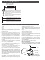
14. Outdoor Antenna Grounding—If an outside antenna or cable system is connected to the
product, be sure the antenna or cable system is grounded so as to provide some protection against
voltage surges and built-up static charges. Article 810 of the National Electrical Code, ANSI/NFPA
70, provides information with regard to proper grounding of the mast and supporting structure,
grounding of the lead-in wire to an antenna discharge unit, size of grounding conductors, location
of antenna-discharge unit, connection to
grounding electrodes, and requirements for the
grounding electrode. See Figure A.
15. Lightning—For added protection for this product during a lightning storm, or when it is left
unattended and unused for long periods of time, unplug it from the wall outlet and disconnect the
antenna or cable system. This will prevent damage to the product due to lightning and power-line
surges.
16. Power Lines—An outside antenna system should not be located in the vicinity of overhead
power lines, other electric light or power circuits, where it can fall into such power lines or circuits.
17. Overloading—Do not overload wall outlets, extension cords, or integral convenience
receptacles as this can result in a risk of fire or electric shock.
18. Object and Liquid Entry—Never push objects of any kind into this product through openings
as they may touch dangerous voltage points or short-out parts that could result in a fire or electric
shock. Never spill liquid of any kind on the product.
19. Servicing—Do not attempt to service this product yourself as opening or removing covers may
expose you to dangerous voltage or other hazards. Refer all servicing to qualified service
personnel.
20. Damage Requiring Service—Unplug this product from the wall outlet and refer servicing to
qualified service personnel under the following conditions:
a. When the power-supply cord or plug is damaged,
b. If liquid has been spilled, or objects have fallen into the product,
c. If the product has been exposed to rain or water,
d. If the product does not operate normally by following the operating instructions. Adjust only
those controls that are covered by the operating instructions as an improper adjustment of other
controls may result in damage and will often require extensive work by a qualified technician to
restore the product to its normal operation,
e. If the product has been dropped or damaged in any way, and
f. When the product exhibits a distinct change in performance—this indicates a need for service.
21. Replacement Parts—When replacement parts are required, be sure the service technician
has used replacement parts specified by the manufacturer or have the same characteristics as
the original part. Unauthorized substitutes may result in fire, electric shock or other hazards.
22. Safety Check—Upon completion of any service or repairs to this product, ask the service
technician to perform safety checks to determine that the product is in proper operating condition.
23. Wall or Ceiling Mounting—The product should be mounted to a wall or ceiling only as
recommended by the manufacturer.
24. Heat—The product should be situated away from heat sources such as radiators, heat
registers, stoves, or other products (including amplifiers) that produce heat.
NOTE TO CATV SYSTEM INSTALLERS:
THIS REMINDER IS PROVIDED TO CALL THE CATV SYSTEM INSTALLER'S ATTENTION TO
ARTICLE 820 - 40 OF THE NEC THAT PROVIDES GUIDELINES FOR PROPER GROUNDING
AND, IN PARTICULAR, SPECIFIES THAT THE CABLE GROUND SHALL BE CONNECTED TO
THE GROUNDING SYSTEM OF THE BUILDING, AS CLOSE TO THE POINT OF CABLE ENTRY
AS PRACTICAL.
EXAMPLE OF ANTENNA GROUNDING
ANTENNA
LEAD IN
WIRE
GROUND CLAMP
ANTENNA
DISCHARGE UNIT
(NEC SECTION 810-20)
ELECTRIC
SERVICE
EQUIPMENT
GROUNDING
CONDUCTORS
(NEC SECTION 810-21)
GROUND CLAMPS
POWER SERVICE GROUNDING ELECTRODE
SYSTEM (NEC ART 250, PART H)
Table of Contents / Description / Specifications
3
TABLE OF CONTENTS
2
2
3
4
5
Caution Statements
Important Safety Instructions
Table of Contents / Description / Specifications
Front Panel Controls and Indicators
Rear Panel Controls and Connections
6
7
9
10
11
Installation / Installation Diagram
Channel Assignments
Internal Jumper Settings
Service / If You Need To Call For Help
Warranty
VM2860 VIDEO MODULATOR
VIDEO
LEVEL
POWER
NORMAL
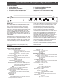
DESCRIPTION
The R.L Drake VM2860 and VM2862 Video Modulators are high
quality, vestigial sideband units with synthesized visual and aural
carriers. They are designed to accept NTSC video and audio
baseband signals from a satellite receiver or similar equipment.
Front panel video and audio level controls with accompanying
modulation indicators permit easy setup of the proper modulation
levels. The A/V ratio and RF output level controls are also provided
on the front panel. A rear panel EAS alternate IF input is also
provided. The VM2860 model is for applications with mono audio
and the VM2862 model provides BTSC stereo encoded audio. If
SAP is required, this option is available for the VM2862 model, and
is field installable.
Synthesized operation provides complete frequency agility, allowing
front panel selection of any standard CATV channel from 2 to 135
(54 to 862 MHz band). FCC required offsets for aeronautical
channels are automatically provided for each channel that requires
an offset. For special applications, IRC or HRC CATV frequencies
or off-air broadcast frequencies can be selected after moving an
internal jumper.
A high quality IF SAW filter with FCC predistortion eliminates
adjacent channel interference and provides optimum delay
characteristics.
A / V RATIO
AUDIO
LEVEL
OVER-MOD
NORMAL
CATV CATV +100
OVER-MOD
RF OUTPUT
CHANNEL
2
5
EAS ACTIVE
An auto-switching alternate IF input, labeled EAS input, is provided
for connection of an Emergency Alert System 44 MHz IF signal.
When the EAS IF signal appears at the EAS input, the main video
and audio modulated IF is replaced by the EAS input signal.
A 4.5 MHz video trap may be selected via an internal jumper
(VM2862 has 4.5 MHz trap on as factory setting). This may be used
to filter off a 4.5 MHz sound subcarrier or undesired video
components to prevent interference to the stereo or SAP channels.
The RF section of the modulator contains bandpass filtering that
divides the 54 to 862 MHz output range into four bands, each
approximately 200 MHz wide. This filtering, in conjunction with the
use of high level, low noise floor mixing, ensures very low
broadband noise at the output. Thus a full complement of up to all
134 available channels from VM2860 or VM2862 modulators may
be combined while maintaining an excellent C/N of each channel.
All of the mentioned features, combined with a carefully designed
low noise and low distortion output stage, provide reliable operation
in a densely crowded SMATV or CATV environment.
The inclusion of a fan in the VM2860 and VM2862 permits rack
mounting of this equipment without leaving the typical 1U air space
between modulators.
SPECIFICATIONS - VM2860 / VM2862
RF
Frequency Range: 54 MHz to 864 MHz.
Standard CATV channels 2 to 135.
Broadcast, HRC, and IRC channel plans available by
internal jumper.
FCC Offsets: Automatic, positive.
Output Level: +60 dBmV minimum, 12 dB minimum adjustment
range.
Amplitude Stability: ± 1 dB.
Output Impedance: 75 Ohms, 12 dB return loss within output filter
passband.
A/V Ratio: -12 dB to -25 dB.
Frequency Stability: ± 5 ppm. All oscillators locked to the same internal
reference.
Spurious Outputs: -60 dBc at +60 dBmV output level, 5 MHz to
1000 MHz, 15 dB A/V ratio.
Phase Noise: -85 dBc at 10 kHz offset.
Output Filter Bands: 54 MHz to 258 MHz, 258 MHz to 462 MHz, 462 MHz
to 660 MHz, 660 MHz to 864 MHz.
Broadband Noise: -80 dBc, 4 MHz bandwidth, +60 dBmV output level,
±18 MHz offset within output filter passband, -90 dBc
outside of output filter passband, output filtered into 4
approximately 200 MHz wide bands.
VIDEO
Input Level: 1 Vp-p ± 3 dB, manual gain adjustment with
modulation indicators.
Input Impedance: 75 Ohms, 25 dB return loss.
Frequency Response: 20 Hz to 4.2 MHz, ± 1 dB with 4.5 MHz trap off,
20 Hz to 4.1 MHz, ±1 dB with 4.5 MHz trap on.
In-channel C/N: 65 dB.
L/C Delay: ±50 nS of FCC predistortion with 4.5 MHz trap off,
-20 +80 nS of FCC predistortion with 4.5 MHz trap on.
Differential Gain: ± 3%.
Differential Phase: ± 30.
MONO AUDIO
Input Level: 250 mVrms to 2.5 Vrms, manual gain adjustment with
LED modulation indicators.
Input Impedance: 10K Ohms, unbalanced.
MONO AUDIO, cont'd.
Pre-emphasis:
Frequency Response :
THD:
S/N:
75 µS.
50 Hz to 15 kHz, ±1 dB.
0.5% maximum.
65 dB.
BTSC STEREO AUDIO (VM2862 only)
Input Level: 250 mVrms to 2.5 Vrms, manual gain adjustment with
LED modulation indicators.
Input Impedance: 10K Ohms, unbalanced.
Separation: 30 db, 50 Hz to 12.5 kHz; 25 dB, 12.5 kHz to 14 kHz.
Frequency Response: ± 0.5 dB, 50 Hz to 14 kHz.
THD: 0.5% maximum.
S/N: 65 dB.
SAP AUDIO Option (VM2862 only)
Input Level: 250 mVrms to 2.5 Vrms, manual gain adjustment with
over-modulation indicator.
Input Impedance: 10K Ohm, unbalanced.
Frequency Response: ±2 dB, 50 Hz to 10 kHz.
THD: 1% maximum.
S/N: 80 dB.
EAS INPUT
Level :
Impedance:
Isolation:
Auto Switching Level:
+30 dBmV, ±1 dB (visual carrier).
75 Ohm, 20 dB return loss.
60 dB.
+20 dBmV.
GENERAL
AC Power: 115 VAC ± 10%, 60 Hz,
23 Watts (VM2860), 28 Watts (VM2862).
Fuse: 1/2 Amp Slo-Blo 5 X 20 mm.
Temperature Range: 0° to 50° C.
Cooling: Internal 1.85 CFM fan allows operation in the rack
without air spaces between units.
Radiated Emissions: FCC Part 15.
Size: 11.25" D x 1.75" H x 19" W
Weight: 8 lbs. 8 oz.
4
Front Panel Controls and Indicators
F1
F2
F6 F7
F4
F8
F9
F10
VM2860 VIDEO MODULATOR
VIDEO
LEVEL
POWER
NORMAL
F3
A / V RATIO
AUDIO
LEVEL
OVER-MOD
CATV CATV +100
OVER-MOD
NORMAL
RF OUTPUT
CHANNEL
2
5
EAS ACTIVE
F5
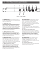
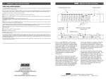
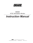
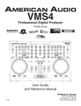
Figure 1 - FRONT PANEL
F1 - POWER Indicator
This LED lights when the unit is connected to a source of
AC power. The LED flashes when on an invalid channel or
if there is a synthesizer error.
F2 - VIDEO LEVEL Control
The setting of this screwdriver adjustment determines the
video modulation level. Clockwise rotation increases the
depth of modulation. After installing the unit, and with a
nominal 1 Vp-p video source connected, adjust the VIDEO
LEVEL control to a point where the red LED modulation
indicator (see item F3) just remains off (87.5% depth of
modulation). It is normal for the green modulation indicator
to be on with only sync level video input.
F3 - MODULATION Indicators (Video)
The green LED will be turned on continuously with sync
level or higher video input. An overmodulation condition is
noted with the red LED turned on continuously. The
VIDEO LEVEL control should be set to a point where the
red LED just remains off (see item F2).
F4 - AUDIO LEVEL Control
The setting of this screwdriver adjustment determines the
audio deviation level. Clockwise rotation increases the
level. After installing the unit and with the audio source
connected, adjust the AUDIO LEVEL control to a point
where the green LED is turned on continuously and the red
LED just remains off (25 kHz peak deviation).
F5 - MODULATION Indicators (Audio)
The green LED will be turned on continuously for peak
deviations of approximately 2.5 kHz (10% of 25 kHz
maximum) or greater. An overmodulation condition is
noted with the red LED turned on continuously. The
AUDIO LEVEL control should be set to a point where the
red LED just remains off (see item F4).
F6 - A/V RATIO Control
This screwdriver adjustment varies the level of the aural
carrier over a range from 12 to 25 dB below the visual
carrier. The aural carrier should be adjusted to
approximately 15 dB below the visual carrier (normal
operation). Clockwise rotation increases the aural carrier
level and thus decreases the A/V ratio.
F7 - EAS ACTIVE Indicator
This indicator lights when a signal is present at the EAS
input (R2) indicating that the modulator has switched to the
EAS signal.
F8 - CATV, CATV +100 CHANNEL Switch
This two position switch allows selection of the desired
operating channel from 02 to 99 (when the switch is in the
CATV position) and channels 100 to 135 (when the switch
is in the CATV +100 position). See the CHANNEL
ASSIGNMENTS section for a list of the corresponding
operating frequency, and offset, if any, for each channel
number.
F9 - CHANNEL Switch
These pushwheel switches allow the selection of the
desired operating channel from 01 to 135. See the
CHANNEL ASSIGNMENTS section for a list of the
corresponding operating frequency, and offset, if any, for
each channel number.
F10 - RF OUTPUT LEVEL Control
This screwdriver adjustment varies the RF OUTPUT level.
Clockwise rotation increases the level.
Rear Panel Controls and Connections
R3 R4
SAP LEVEL
MADE IN THE U.S.A. BY
®
R8
SAP AUDIO IN
AUDIO IN
RF OUTPUT
L
EAS IN
SERIAL #
VIDEO IN
R
SAP
OVERMODULATION
5
R10
CAUTION:-
RISK OF
FIRE-REPLACE FUSE AS
MARKED AFTER
DISCONNECTING
UNIT FROM AC LINE.
FUSE
.5 A / 250 V
SLO-BLO
115 VAC, 60 Hz
27 WATT
ATTENTION:
-RISQUE D'INCENIDEREMPLACEZ FUSIBLE DU
TYPE INDIQUÉ APRÉS
DEBRANCHER DU SECTEUR.
R1
R2
R5
R6
R7
R9
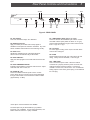
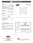
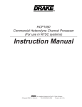
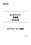
Figure 2 - REAR PANEL
R1 - RF OUTPUT
This is the modulator output, 54 to 864 MHz.
R2 - EAS IN Connector
Apply a 44 MHz (45.75 MHz video carrier) signal at
30 dBmV to this input from an EAS IF modulator. Any level
above +20 dBmV will activate the auto switching circuitry.
R3 - SAP Level *
Adjusts the modulation level of the SAP subcarrier.
Advance level until indicator R5 just illuminates.
R4 - SAP AUDIO IN *
Apply the audio program for the SAP audio channel to this
input.
R5 - SAP OVERMODULATION *
Indicates overmodulation of the SAP audio channel. Adjust
audio with SAP level control, R3.
R6 - AUDIO IN, L/R
These are unbalanced audio inputs to the IF circuits.
These “RCA” (phono) connector inputs accept baseband
through 15 kHz audio at a nominal level of 250 mV RMS
(approximately -10 dBu).
* SAP option must be installed in the VM2862.
The SAP option may be field installed, by a qualified
technician, into a VM2862. For purchase information, call
Drake Customer Service at 1 (937) 746-6990.
R7 - VIDEO INPUT ("RCA" type or "F" type)
These are used as the baseband input to the IF circuits.
Use ONE of these inputs (either the "RCA" or "F" type)
which accepts baseband through 4.2 MHz video at levels
from 0.7 Vp-p to 1.5 Vp-p.
R8 - Fan Vents
To ensure proper cooling of the unit, do not block these
vents for the cooling fan.
R9 - FUSE
Always replace this fuse with one of the same type and
rating: .5 Amp, 250 V SLO-BLO®, 5 x 20 mm type.
R10 - LINE CORD
This is a three-wire power cable. When the cable is
connected to a properly wired AC power line outlet, this
cable grounds the instrument cabinet. Connect to a
nominal 115 VAC ±10%, 60 Hz source. Do not defeat the
safety purpose of the center ground prong on the attached
line cord plug.
6
Installation / Installation Diagram
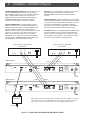
CONNECTIONS AND CONTROLS - All connections to and
from the VM2860/VM2862 are made through the rear
panel. Figure 3 shows a typical two channel installation
using a typical satellite receiver as a signal source.
Additional channels can be added by using additional
VM2860/VM2862 modulators and either multi-port
combiners or combinations of two-port combiners.
INSTALLATION NOTES - Level adjustment provides
optimum performance in multichannel installations. The
modulator outputs should be checked periodically with a
spectrum analyzer to maintain a ±1 dB variation of
adjacent channel carriers. Aural/Visual (A/V) ratios should
be held to -15 dB or less. The 'Output Level' and 'A/V
Ratio' controls are used respectively to make these
adjustments. If an output level of less than +50 dBmV is
required from the VM2860/VM2862, add an attenuator of
the appropriate value to the modulator output.
Example: For an output level of +45 dBmV, add a 12 dB
attenuator pad to the modulator output and set the
VM2860/VM2862 output level to +57 dBmV ahead of
the pad.
RACK MOUNTING - Adequate ventilation is very important
in multichannel installations. Units should be spaced apart
by at least one panel height wherever possible, and some
air movement is advisable in enclosed rack cabinets.
Excessive heat will shorten component life and modulator
performance will be degraded without proper cooling.
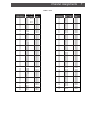
FCC PART 76.612 - The VM2860/VM2862 synthesizer has
been programmed to comply with FCC requirements for
offsets on cable channel frequencies assigned to aviation
and navigation communications. The programmed offset
for each channel is listed in the following chart.
TYPICAL SATELLITE RECEIVER
REAR PANEL
AUDIO
OUT
L
R
V
H
TYPICAL SATELLITE RECEIVER
REAR PANEL
VIDEO
OUT
H
V
AUDIO
OUT
L
R
VIDEO
OUT
VM2860/VM2862
AUDIO
SAP LEVEL
MADE IN THE U.S.A. BY
®
SAP AUDIO IN
AUDIO IN
RF OUTPUT
L
EAS IN
SERIAL #
VIDEO
VIDEO IN
R
SAP
OVERMODULATION
CAUTION:-
RISK OF
FIRE-REPLACE FUSE AS
MARKED AFTER
DISCONNECTING
UNIT FROM AC LINE.
FUSE
.5 A / 250 V
SLO-BLO
115 VAC, 60 Hz
27 WATT
FUSE
.5 A / 250 V
SLO-BLO
115 VAC, 60 Hz
27 WATT
ATTENTION:
-RISQUE D'INCENIDEREMPLACEZ FUSIBLE DU
TYPE INDIQUÉ APRÉS
DEBRANCHER DU SECTEUR.
VM2860/VM2862
AUDIO
SAP LEVEL
MADE IN THE U.S.A. BY
®
VIDEO
SAP AUDIO IN
AUDIO IN
RF OUTPUT
L
SERIAL #
EAS IN
VIDEO IN
R
SAP
OVERMODULATION
CAUTION:-
RISK OF
FIRE-REPLACE FUSE AS
MARKED AFTER
DISCONNECTING
UNIT FROM AC LINE.
ATTENTION:
-RISQUE D'INCENIDEREMPLACEZ FUSIBLE DU
TYPE INDIQUÉ APRÉS
DEBRANCHER DU SECTEUR.
COMBINER
NOTE: When connecting the audio output of a stereo receiver to a VM2860, connect both
Left and Right channels. The VM2860 will sum these to make a complete mono audio
signal. When a mono source is used, either input of the VM2860 may be chosen.
RF OUT
Figure 3 - TYPICAL MULTIPLE MODULATOR INSTALLATION
Channel Assignments
TABLE 1: CATV
EIA CH# /
Output Channel
Switch Setting
01
02
03
04
05
06
07
08
09
10
11
12
13
14
15
16
17
18
19
20
21
22
23
24
25
26
27
28
29
30
31
32
33
34
35
36
37
38
39
40
41
42
43
44
45
46
47
48
49
50
51
52
53
54
55
56
57
58
59
60
61
62
63
64
65
66
67
68
Visual Carrier
Frequency (MHz)
STD
IRC
N/A
73.25
55.25
61.25
67.25
79.25
77.25
85.25
83.25
175.25
181.25
187.25
193.25
199.25
205.25
211.25
121.2625
127.2625
133.2625
139.25
145.25
151.25
157.25
163.25
169.25
217.25
223.2625
229.2625
235.2625
241.2625
247.2625
253.2625
259.2625
265.2625
271.2625
277.2625
283.2625
289.2625
295.2625
301.2625
307.2625
313.2625
319.2625
325.2625
331.275
337.2625
343.2625
349.2625
355.2625
361.2625
367.2625
373.2625
379.2625
385.2625
391.2625
397.2625
403.25
409.25
415.25
421.25
427.25
433.25
439.25
445.25
451.25
457.25
463.25
469.25
475.25
481.25
487.25
HRC
72.00
54.00
60.00
66.00
78.00
84.00
174.00
180.00
186.00
192.00
198.00
204.00
210.00
120.00
126.00
132.00
138.00
144.00
150.00
156.00
162.00
168.00
216.00
222.00
228.00
234.00
240.00
246.00
252.00
258.00
264.00
270.00
276.00
282.00
288.00
294.00
300.00
306.00
312.00
318.00
324.00
330.00
336.00
342.00
348.00
354.00
360.00
366.00
372.00
378.00
384.00
390.00
396.00
402.00
408.00
414.00
420.00
426.00
432.00
438.00
444.00
450.00
456.00
462.00
468.00
474.00
480.00
486.00
EIA CH# /
Output Channel
Switch Setting
69
70
71
72
73
74
75
76
77
78
79
80
81
82
83
84
85
86
87
88
89
90
91
92
93
94
95
96
97
98
99
100
101
102
103
104
105
106
107
108
109
110
111
112
113
114
115
116
117
118
119
120
121
122
123
124
125
126
127
128
129
130
131
132
133
134
135
Visual Carrier
Frequency (MHz)
STD
IRC
493.25
499.25
505.25
511.25
517.25
523.25
529.25
535.25
541.25
547.25
553.25
559.25
565.25
571.25
577.25
583.25
589.25
595.25
601.25
607.25
613.25
619.25
625.25
631.25
637.25
643.25
91.25
97.25
103.25
109.275
115.275
649.25
655.25
661.25
667.25
673.25
679.25
685.25
691.25
697.25
703.25
709.25
715.25
721.25
727.25
733.25
739.25
745.25
751.25
757.25
763.25
769.25
775.25
781.25
787.25
793.25
799.25
805.25
811.25
817.25
823.25
829.25
835.25
841.25
847.25
853.25
859.25
HRC
492.00
498.00
504.00
510.00
516.00
522.00
528.00
534.00
540.00
546.00
552.00
558.00
564.00
570.00
576.00
582.00
588.00
594.00
600.00
606.00
612.00
618.00
624.00
630.00
636.00
642.00
90.00
96.00
102.00
108.00
114.00
648.00
654.00
660.00
666.00
672.00
678.00
684.00
690.00
696.00
702.00
708.00
714.00
720.00
726.00
732.00
738.00
744.00
750.00
756.00
762.00
768.00
774.00
780.00
786.00
792.00
798.00
804.00
810.00
816.00
822.00
828.00
834.00
842.00
848.00
854.00
860.00
7
8
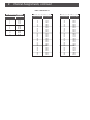
Channel Assignments, continued
TABLE 2: BROADCAST TV
VHF BROADCAST CHANNELS
Channel Number
Visual Carrier
Frequency (MHz)
2
3
4
5
6
7
8
9
10
11
12
13
55.25
61.25
67.25
77.25
83.25
175.25
181.25
187.25
193.25
199.25
205.25
211.25
UHF BROADCAST CHANNELS
UHF BROADCAST CHANNELS
Channel Number
Visual Carrier
Frequency (MHz)
Channel Number
Visual Carrier
Frequency (MHz)
14
15
16
17
18
19
20
21
22
23
24
25
26
27
28
29
30
31
32
33
34
35
36
37
38
39
40
41
471.25
477.25
483.24
489.25
495.25
501.25
507.25
513.25
519.25
525.25
531.25
537.25
543.25
549.25
555.25
561.25
567.25
573.25
579.25
585.25
591.25
597.25
603.25
609.25
615.25
621.25
627.25
633.25
42
43
44
45
46
47
48
49
50
51
52
53
54
55
56
57
58
59
60
61
62
63
64
65
66
67
68
69
639.25
645.25
651.25
657.25
663.25
669.25
675.25
681.25
687.25
693.25
699.25
705.25
711.25
717.25
723.25
729.25
735.25
741.25
747.25
753.25
759.25
765.25
771.25
777.25
783.25
789.25
795.25
801.25
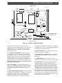
Internal Jumper Settings
9
REAR PANEL
(2) IF LOOP
(5) AUDIO LOOP
(6) VIDEO LED
(7) CLAMP
NORM SLOW
(3) AUDIO PRE-EMPHASIS
ON OFF
OFF ON
(8) 4.5 MHz TRAP
VM2862
VM2860
(4) MODEL
SETTING
IRC
(1) CHANNEL PLAN
HRC NO JUMPER = STD
BCTV
FRONT PANEL
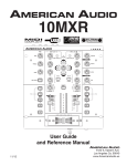
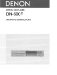
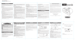
Figure 4 - INTERNAL JUMPER SETTINGS
There are a number of internal jumpers that may be
programmed to change certain parameters from the factory
default settings. Some of these jumpers should not be
changed in the field. In most cases, the factory default
settings should prevail.
(1) - CHANNEL PLAN JUMPER - The factory setting for
this configuration is to have no jumper. This provides a
standard EIA CATV plan. If IRC frequencies are required,
add a shorting jumper across the two pins pointed out by
the IRC arrow in Figure 4. For HRC, use the two pins
indicated for HRC. If broadcast frequency assignments are
needed, jumper the two pins indicated by the BCTV arrow.
NOTE: Never install more than one shorting jumper at a
time at this block of headers.
(2) IF LOOP JUMPER - The factory setting is shown in
Figure 4. If this jumper is removed, the 44 MHz IF loop will
be opened and the modulator output will go away. This is
used for special applications and will not normally be
changed.
(3) AUDIO PRE-EMPHASIS JUMPER - This jumper should
normally be in the ON position to enable the 75 µSec audio
pre-emphasis. ON is the correct setting for both the
VM2860 and VM2862 models. If the VM2860 model is
used with an external stereo encoder that provides the
pre-emphasis, VM2860 pre-emphasis may be defeated by
moving this jumper to OFF. The VM2862 internal stereo
encoder requires this setting to be ON.
(4) MODEL SETTING - This jumper must be set to match
the model number of this modulator.
(5 & 6) AUDIO LOOP and VIDEO LED - These jumpers
must be present in the VM2860. They are not present in
the VM2862.
(7) CLAMP JUMPER - This jumper affects the time
constant of the video clamp. The factory setting is NORM.
(8) 4.5 MHz TRAP - The factory settings are OFF for the
VM2860 and ON for the VM2862. When set to ON, a
4.5 MHz notch filter is inserted in the video input path to
prevent any possible 4.5 MHz energy in the video from
interfering with the stereo or SAP performance. A slight
degradation in video response and LC delay is incurred.
The VM2862 thus requires an ON setting for the jumper.
Mono operation is less critical and the default setting for
the VM2860 is OFF. If audio interference from the video
source is observed on the VM2860, move this jumper to
the ON position. See the Specifications section for details
of the jumper's affect on performance.
10
Service / If You Need To Call For Help
SERVICE INFORMATION
You may contact the R.L. DRAKE Service Department for
additional information or assistance by calling
+1 (937) 746-6990, Monday through Friday, between
8:00 A.M. and 4:00 P.M. Eastern Time, except on holidays.
You may also contact the R.L. DRAKE Service Department by
E-mail at the following address:
[email protected]
or by Telefax:
+1 (937) 743-4576.
IF YOU NEED TO CALL FOR HELP
Call our Customer Service/Technical Support line at
+1 (937) 746-6990 between 8:00 A.M. and 4:00 P.M.
Eastern Time, weekdays. Please have the unit’s serial
number available. We will also need to know the specifics of
any other equipment connected to the unit.
When calling, please have the unit up and running, near the
phone if possible. Our technician(s) will likely ask certain
questions to aid in diagnosis of the problem. Also, have a
voltmeter handy, if possible.
R.L. DRAKE also provides technical assistance by
e-mail: [email protected]
or by Telefax: +1 (937) 743-4576.
Many of the products that are sent to us for repair are in
perfect working order when we receive them. For these
units, there is a standard checkout fee that you will be
charged. Please perform whatever steps are applicable
from the installation sections of the Owner's Manual before
calling or writing—this could save unnecessary phone
charges. Please do not return the unit without contacting
R.L. DRAKE first: it is preferred to help troubleshoot the
problem over the phone (or by mail) first, saving you both
time and money.
Inside the carton, enclose a note with your name, address,
daytime phone number, and a description of the unit’s
problem.
The unit must be sent to the following address:
Service Department
R.L. DRAKE COMPANY
230 Industrial Drive
Franklin, Ohio 45005 U.S.A.
Be sure to include your street address which will be needed
for UPS return. UPS Surface (Brown Label) takes 7-10 days
to reach us depending on your location, Blue takes 2-3
days.
Should you want to return your unit for service, package the
unit carefully using the original carton or other suitable
container.
Write your return address clearly on the shipping carton and
on an enclosed cover letter describing the service required,
symptoms or problems. Also include your daytime telephone number and a copy of your proof of purchase.
The unit will be serviced under the terms of the
R.L. DRAKE COMPANY Limited Warranty and returned
to you.
Red is an overnight service. Send the unit in a way that it
can be traced if we can’t verify receipt of shipment. We
suggest UPS or insured postal shipment.
If the unit is still under the original owner’s warranty,
R.L. DRAKE will pay the cost of the return shipment to you.
Our return shipping policy is that we will return it UPS Brown
if received Brown or by US Mail, it will be returned Blue if
received Blue or Red—or it will be returned however you
prefer if you furnish the return cost for the method you
select.
If the unit is out of warranty, use one of the following
methods for return shipment:
1) You designate billing to American ExPress, VISA,
MasterCard or Discover card;
2) You prepay the service charges with a personal check,
or
3) You specify some other method of return and payment.
When calling, the technician can estimate the repair charges
for you over the phone. This is another good reason to call
before sending a unit in for repair.
Typically, equipment is repaired in five to ten working days
after it arrives at R.L. DRAKE if we have all the facts. If we
must call you, it may take longer. R.L. DRAKE is not
responsible for damage caused by lightning, nonprofessional alterations, “acts of God”, shipping damage, poor
storage/handling, etc. R.L. DRAKE will make note of any
shipping damage upon receipt.
You will need to send proof of purchase to receive warranty
service. Typically, a copy of the invoice from an R.L. DRAKE
dealer will suffice. The warranty is for the original owner only
and is not transferable.
Warranty
11
Warranty
Three Year Limited Warranty
R.L. DRAKE COMPANY warrants to the original purchaser this product shall be free from defects in material or
workmanship for three (3) years from the date of original purchase.
During the warranty period the R.L. DRAKE COMPANY or an authorized Drake service facility will provide, free
of charge, both parts and labor necessary to correct defects in material and workmanship. At its option,
R.L. DRAKE COMPANY may replace a defective unit.
To obtain such a warranty service, the original purchaser must:
(1) Retain invoice or original proof of purchase to establish the start of the warranty period.
(2) Notify the R.L. DRAKE COMPANY or the nearest authorized service facility, as soon as possible after discovery
of a possible defect, of:
(a) the model and serial number,
(b) the identity of the seller and the approximate date of purchase; and
(c) A detailed description of the problem, including details on the electrical connection to associated equipment and
the list of such equipment.
(3) Deliver the product to the R.L. DRAKE COMPANY or the nearest authorized service facility, or ship the same
in its original container or equivalent, fully insured and shipping charges prepaid.
Correct maintenance, repair, and use are important to obtain proper performance from this product. Therefore
carefully read the Instruction Manual. This warranty does not apply to any defect that R.L. DRAKE COMPANY
determines is due to:
(1) Improper maintenance or repair, including the installation of parts or accessories that do not conform to the
quality and specifications of the original parts.
(2) Misuse, abuse, neglect or improper installation.
(3) Accidental or intentional damage.
All implied warranties, if any, including warranties of merchantability and fitness for a particular purpose, terminate
three (3) years from the date of the original purchase.
The foregoing constitutes R.L. DRAKE COMPANY’S entire obligation with respect to this product, and the original
purchaser shall have no other remedy and no claim for incidental or consequential damages, losses or expenses.
Some states do not allow limitations on how long an implied warranty lasts or do not allow the exclusions or
limitation of incidental or consequential damages, so the above limitation and exclusion may not apply to you.
This warranty gives you specific legal rights and you may also have other rights which vary from state to state.
This warranty shall be construed under the laws of Ohio.
For Service, contact:
R.L. DRAKE COMPANY
230 Industrial Drive
Franklin, Ohio 45005 U.S.A.
Customer Service and Parts Telephone: +1 (937) 746-6990
Telefax: +1 (937) 743-4576
World Wide Web Site: http://www.rldrake.com
R.L. Drake Company
230 Industrial Drive
Franklin, Ohio 45005 U.S.A.
Customer Service and Parts Telephone: +1 (937) 746-6990
Telefax: +1 (937) 743-4576
World Wide Web Site: http://www.rldrake.com