1
4
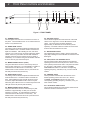
Front Panel Controls and Indicators
F1
F2
F6 F7
F4
F8
F9
F10
VM2860 VIDEO MODULATOR
VIDEO
LEVEL
POWER
NORMAL
F3
A / V RATIO
AUDIO
LEVEL
OVER-MOD
CATV CATV +100
OVER-MOD
NORMAL
RF OUTPUT
CHANNEL
2
5
EAS ACTIVE
F5
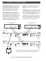
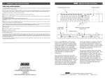
Figure 1 - FRONT PANEL
F1 - POWER Indicator
This LED lights when the unit is connected to a source of
AC power. The LED flashes when on an invalid channel or
if there is a synthesizer error.
F2 - VIDEO LEVEL Control
The setting of this screwdriver adjustment determines the
video modulation level. Clockwise rotation increases the
depth of modulation. After installing the unit, and with a
nominal 1 Vp-p video source connected, adjust the VIDEO
LEVEL control to a point where the red LED modulation
indicator (see item F3) just remains off (87.5% depth of
modulation). It is normal for the green modulation indicator
to be on with only sync level video input.
F3 - MODULATION Indicators (Video)
The green LED will be turned on continuously with sync
level or higher video input. An overmodulation condition is
noted with the red LED turned on continuously. The
VIDEO LEVEL control should be set to a point where the
red LED just remains off (see item F2).
F4 - AUDIO LEVEL Control
The setting of this screwdriver adjustment determines the
audio deviation level. Clockwise rotation increases the
level. After installing the unit and with the audio source
connected, adjust the AUDIO LEVEL control to a point
where the green LED is turned on continuously and the red
LED just remains off (25 kHz peak deviation).
F5 - MODULATION Indicators (Audio)
The green LED will be turned on continuously for peak
deviations of approximately 2.5 kHz (10% of 25 kHz
maximum) or greater. An overmodulation condition is
noted with the red LED turned on continuously. The
AUDIO LEVEL control should be set to a point where the
red LED just remains off (see item F4).
F6 - A/V RATIO Control
This screwdriver adjustment varies the level of the aural
carrier over a range from 12 to 25 dB below the visual
carrier. The aural carrier should be adjusted to
approximately 15 dB below the visual carrier (normal
operation). Clockwise rotation increases the aural carrier
level and thus decreases the A/V ratio.
F7 - EAS ACTIVE Indicator
This indicator lights when a signal is present at the EAS
input (R2) indicating that the modulator has switched to the
EAS signal.
F8 - CATV, CATV +100 CHANNEL Switch
This two position switch allows selection of the desired
operating channel from 02 to 99 (when the switch is in the
CATV position) and channels 100 to 135 (when the switch
is in the CATV +100 position). See the CHANNEL
ASSIGNMENTS section for a list of the corresponding
operating frequency, and offset, if any, for each channel
number.
F9 - CHANNEL Switch
These pushwheel switches allow the selection of the
desired operating channel from 01 to 135. See the
CHANNEL ASSIGNMENTS section for a list of the
corresponding operating frequency, and offset, if any, for
each channel number.
F10 - RF OUTPUT LEVEL Control
This screwdriver adjustment varies the RF OUTPUT level.
Clockwise rotation increases the level.