1
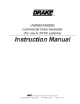
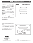
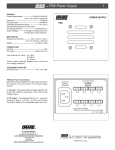
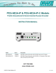
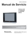
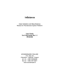
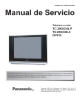
DSE 2 PLUS
Dual HD Digital Encoder with Multiplexed QAM Output
INSTRUCTION MANUAL
is a registered trademark of R.L. Drake Holdings, LLC.
© Copyright 2014 R. L. Drake Holdings, LLC P/N 651232800 A
Printed in U.S.A.
DSE 2 PLUS | 2
Instruction Manual
Rev: 20140701
Table of Contents
IMPORTANT SAFETY INSTRUCTIONS ...................................................................................................................................................... 2
SPECIFICATIONS ............................................................................................................................................................................................ 4
GENERAL DESCRIPTION .............................................................................................................................................................................. 6
FEATURES ........................................................................................................................................................................................................ 6
INSTALLATION AND MOUNTING.............................................................................................................................................................. 6
REAR PANEL CONNECTIONS ..................................................................................................................................................................... 7
ETHERNET ACCESS ....................................................................................................................................................................................... 8
SETUP AND PROGRAMMING ................................................................................................................................................................... 10
FIRMWARE UPDATE .................................................................................................................................................................................... 14
SERVICE / IF YOU NEED TO CALL FOR HELP ........................................................................................................................................ 18
WARRANTY .............................................................................................................................................................................................................. 19
Caution Statements:
WARNING: TO PREVENT FIRE OR ELECTRICAL
SHOCK, DO NOT EXPOSE TO RAIN OR MOISTURE.
A product and cart combination should be moved
with care.
Quick stops, excessive force and uneven surfaces may
cause the product and cart combination to overturn.
The lightning flash with arrow head symbol, within an
equilateral triangle, is intended to alert the user to
the presence of uninsulated "dangerous voltage"
within the product's enclosure that may be of
sufficient magnitude to constitute a risk of electric
shock to persons.
The exclamation point within an equilateral triangle
is intended to alert the user to the presence of
important operating and maintenance (servicing)
instructions in the literature accompanying the
product.
WARNING:
THE SOCKET-OUTLET SHALL BE INSTALLED NEAR THE EQUIPMENT AND SHALL BE EASILY ACCESSIBLE.
WARNING:
TO REDUCE THE RISK OF FIRE OR ELECTRIC SHOCK, DO NOT EXPOSE THIS PRODUCT TO RAIN OR
MOISTURE. DO NOT OPEN THE CABINET, REFER SERVICING TO QUALIFIED PERSONNEL ONLY.
CAUTION:
TO PREVENT ELECTRIC SHOCK, DO NOT USE THIS (POLARIZED) PLUG WITH AN EXTENSION CORD
RECEPTACLE OR OTHER OUTLET UNLESS THE BLADES CAN BE FULLY INSERTED TO PREVENT BLADE
EXPOSURE.
ATTENTION: POUR PREVENIR LES CHOCS ELECTRIQUES, NE PAS UTILISER CETTE FICHE POLARISEE AVEC UN
PROLONGATEUR, UNE PRISE DE COURANT OU UNE AUTRE SORTIE DE COURANT, SAUF SI LES LAMES
PEUVENT ETRE INSEREES A FOND SANS EN LAISSER AUCUNE PARTIE A DECOUVERT.
Important Safety Instructions:
1.
2.
3.
4.
5.
6.
7.
8.
Read Instructions: All the safety and operating instructions should be read before the product is operated.
Retain Instructions: The safety and operating instructions should be retained for future reference.
Heed Warnings: All warnings on the product and in the operating instructions should be adhered to.
Follow Instructions: All operating and use instructions should be followed.
Cleaning: Unplug this product from the wall outlet before cleaning. Do not use liquid cleaners or aerosol cleansers. Use a damp cloth for cleaning.
Attachments: Do not use attachments that are not recommended by the product manufacturer as they may cause hazards.
Water and Moisture: Do not use this product near water—for example, near a bathtub, wash bowl, kitchen sink or laundry tub; in a wet basement;
or near a swimming pool; and the like.
Accessories: Do not place this product on an unstable cart, stand, tripod, bracket, or table. The product may fall, causing serious injury to a child or
adult, and serious damage to the product. Use only with a cart, stand, tripod, bracket, or table recommended by the manufacturer, or sold with the
DSE 2 PLUS | 3
Instruction Manual
9.
10.
11.
12.
13.
14.
15.
16.
17.
18.
19.
product. Any mounting of the product should follow the manufacturer's instructions, and should use a mounting accessory recommended by the
manufacturer.
A product and cart combination should be moved with care. Quick stops, excessive force, and uneven surfaces may cause the product and cart combination
to overturn.
Ventilation: Slots and openings in the cabinet are provided for ventilation and to ensure reliable operation of the product and to protect it from overheating,
and these openings must not be blocked or covered. The openings should never be blocked by placing the product on a bed, sofa, rug, or similar
surface. This product should not be placed in a built-in installation such as bookcase or rack unless proper ventilation is provided or the manufacturer's
instructions have been adhered to.
Power Sources: This product should be operated only from the type of power source indicated on the marking label. If you are not sure of the type of power
supplied to your home, consult your product dealer or local power company. For products intended to operate from battery power, or other sources, refer to the
product's operating instructions.
Grounding or Polarization: This product may be equipped with a polarized alternating-current line plug (a plug having one blade wider than the
other). This plug will fit into the power outlet only one way. This is a safety feature. If you are unable to insert the plug fully into the outlet, try reversing
the plug. If the plug should still fail to fit, contact your electrician to replace your obsolete outlet. Do not defeat the safety purpose of the polarized
plug. Alternate Warnings – If this product is equipped with a three-wire grounding- type plug, a plug having a third (grounding) pin, the plug will only fit
into a grounding-type power outlet. This is a safety feature. If you are unable to insert the plug into the outlet, contact your electrician to replace your
obsolete outlet. Do not defeat the safety purpose of the grounding-type plug.
Outdoor Antenna Grounding: If an outside antenna or cable system is connected to the product, be sure the antenna or cable system is
grounded so as to provide some protection against voltage surges and built-up static charges. Article 810 of the National Electrical Code,
ANSI/NFPA 70, provides information with regard to proper grounding of the mast and supporting structure, grounding of the lead-in wire
to an antenna discharge unit, size of grounding conductors, location of antenna-discharge unit, connection to grounding electrodes, and
requirements for the grounding electrode.
Power-Cord Protection: Power-supply cords should be routed so that they are not likely to be walked on or pinched by items placed upon or against them,
paying particular attention to cords at plugs, convenience receptacles, and the point where they exit from the product.
Lightning: For added protection for this product during a lightning storm, or when it is left unattended and unused for long periods of time, unplug it
from the wall outlet and disconnect the antenna or cable system. This will prevent damage to the product due to lightning and power-line surges.
Power Lines: An outside antenna system should not be located in the vicinity of overhead power lines, other electric light or power circuits, where it
can fall into such power lines or circuits. When installing an outside antenna system, extreme care should be taken to keep from touching such power
lines or circuits as contact with them may be fatal.
Overloading: Do not overload wall outlets, extension cords, or integral convenience receptacles as this can result in a risk of fire or electric shock.
Object and Liquid Entry: Never push objects of any kind into this product through openings as they may touch dangerous voltage points or short-out
parts that could result in a fire or electric shock. Never spill liquid of any kind on the product.
Servicing: Do not attempt to service this product yourself as opening or removing covers may expose you to dangerous voltage or other hazards.
Refer all servicing to qualified service personnel.
20. Damage Requiring Service: Unplug this product from the wall outlet and refer servicing to qualified service personnel under the following conditions:
a) When the power-supply cord or plug is damaged,
b) If liquid has been spilled, or objects have fallen into the product,
c) If the product has been exposed to rain or water,
d) If the product does not operate normally by following the operating instructions.
Adjust only those controls that are covered by the operating instructions as an improper adjustment of other controls may result in damage and will
often require extensive work by a qualified technician to restore the product to its normal operation, e. If the product has been dropped or damaged
in any way, and f. When the product exhibits a distinct change in performance—this indicates a need for service.
21. Replacement Parts: When replacement parts are required, be sure the service technician has used replacement parts specified by the manufacturer
or have the same characteristics as the original part. Unauthorized substitutes may result in fire, electric shock or other hazards.
22. Safety Check: Upon completion of any service or repairs to this product, ask the service technician to perform safety checks to determine that the
product is in proper operating condition.
23. Wall or Ceiling Mounting: The product should be mounted to a wall or ceiling only as recommended by the manufacturer.
DSE 2 PLUS | 4
Instruction Manual
Specifications
DRAKE DSE 2 PLUS HD ENCODER W/QAM OUTPUT
1002583
ENCODER - Video (Specifications are per Encoder)
Video Inputs:
VGA (with pass-through to monitor)
HDMI (non-HDCP Copy Protected)
Component (Y-Cr-Cb)
Composite (via Y-Input for 480i)
Video Resolution Modes:
480i
480p
720p
1080i
Video Input Resolution Detection:
Yes, automatic
Video Compression Format:
MPEG2 or MPEG4 / H.264
Video Adjustments:
Brightness, Contrast, Hue, Saturation, Sharpness
MPEG4 / H.264 Profiles Supported:
Simple, Advanced Simple, High
Bitrate:
0.000 to 19 Mbps (depending on format)
(640x480 / 720x480 @ 30 fps)
(640x480 / 720x480 @ 60 fps)
(1280x 720 @ 60 fps)
(1920x1080 @ 30 fps)
ENCODER - Audio (Specifications are per Encoder)
Audio Inputs:
PCM
Audio Compression Formats:
HDMI-embedded audio, 32 - 192 kHz sample rate
RCA-type L + R 1 x 1 Vrms nominal
3.5 Vrms max supports +/- 15 dB gain adjustment
Dolby Digital® or MPEG1, Layer 2
DSE 2 PLUS | 5
Instruction Manual
Specifications (continued)
DRAKE DSE 2 PLUS HD ENCODER W/QAM OUTPUT
1002583
QAM (Quadrature Amplitude Modulation) Modulator / Multiplexer (per chassis)
QAM Output Modes:
64 QAM or 256 QAM, ITU Annex B
Frequency Coverage:
54 - 1002 MHz
Channel Plans:
Standard CATV, HRC, IRC, Broadcast
Maximum Output Power Level:
+ 45 dBmV
Level Adjustment Range:
15 dB
Phase Noise:
- 95 dBc @ 10 kHz offset
Broadband Noise:
- 75 dBc @ > +/- 12 MHz
MER:
> 40 dB equalized
Channel Frequency Response:
< 1 dB
Carrier Suppression:
> 40 dB
I/Q Inbalance:
< 1 degree
Output Level Accuracy:
+/- 1 dB
Physical Specifications
Form Factor:
1RU 19" rack mountable
Control:
On-board Ethernet Connection
Power Requirements:
+5 V @ 3.5A via supplied external
Dimensions:
power supply 10.5’’D x 2.0’’H x 19’’ W
Weight:
4.5 lbs.
Temperature Rating:
0 - 50 C ambient
Specifications, price, and availability are subject to change without notice or obligation.
DSE 2 PLUS | 6
Instruction Manual
General Description
The DSE 2 PLUS encodes up to two uncompressed programs from devices with HDMI (non HDCP
encrypted), High-Resolution Component Video, Composite or VGA outputs. The DSE 2 PLUS encodes the
incoming programs to MPEG2 or MPEG4/H.264 compressed video. An internal multiplexing QAM
modulator and low-noise upconverter allows programs to be combined with existing digital and or
analog programming.
Features
•
•
•
•
•
•
•
Receives High-Resolution Component, VGA, or HDMI (non-HDCP content-protection) From Two
Separate Video Sources
Video Encodes to MPEG2 or MPEG4/H.264
Supports 480i, 480p, 720p, or 1080i video resolution
Audio Encoding to Dolby Digital® or MPEG1-Layer 2
Supports Closed Captioning
High Level (+45 dBmV) agile output programmable from 5 to 1,000 MHz using STD, HRC, IRC,
and Broadcast channel plans
GUI-based Remote Network Control and Monitoring
Installation and Mounting
The DSE 2 Plus is designed to be installed in a standard 19’’ rack.
Adequate ventilation is very important in multichannel installations. Units should be spaced apart by at
least one panel height wherever possible, and some air movement is advisable in enclosed rack
cabinets. Excessive heat will shorten component life and modulator performance will be degraded
without proper cooling.
DSE 2 PLUS | 7
Instruction Manual
Rear Panel Connections
All connections are made on the rear panel.
R6 R7 R8
R1
R2
R3
R4
R12 R13
R5
R9
R14
R10 R11 R15 R16 R17
R1 - RF Output – This type “F” connector is a
high level (+29.5 dBmV to +45 dBmV), agile 5 to
1002 MHz, multiplexed output from the DSE2
Plus RF output section.
R7 – Closed Caption Input 1 - This connector
provides the means to input closed captioning.
It requires analog composite video that contains
closed captioning.
R2 – DC Power Connector – This connector
provides the means for connection to the 5 VDC
output of the supplied external power supply.
R8 – VGA Loop Output 1 - This connector
provides VGA video output to a monitor or
other equipment requiring VGA input. It is only
active when VGA is input on R4.
R3 – Component Input 1 - These three color
coded RCA connectors, Cr (red), Cb (blue), and Y
(green), provide the means to input component
video. To input composite video, use the green
‘Y’ connector.
R4 – VGA Input 1 - This VGA type connector
provides the means to input VGA video from a
computer or other device with VGA output.
R5 – HDMI Input 1 - This connector provides
the means to input HDMI video (without HDCP)
with optional embedded audio.
R6 – Audio Input 1 - These two color coded RCA
vtype connectors provide baseband audio Left
(white) and Right (red) inputs to the DSE2 Plus.
R9 – Component Input 2 - These three color
coded RCA connectors, Cr (red), Cb (blue), and Y
(green), provide the means to input component
video. To input composite video, use the green
‘Y’ connector.
R10 – VGA Input 2 - This VGA type connector
provides the means to input VGA video from a
computer or other device with VGA output.
R11 – HDMI Input 2 - This connector provides
the means to input HDMI video (without HDCP)
with optional embedded audio.
DSE 2 PLUS | 8
Instruction Manual
Rear Panel Connections (continued)
R12 – Audio Input 2 - These two color coded
RCA type connectors provide baseband audio
Left (white) and Right (red) inputs to the DSE2
Plus.
R13 – Closed Caption Input 2 - This connector
provides the means to input closed captioning.
It requires analog composite video that contains
closed captioning.
R14 – VGA Loop Output 2 - This connector
provides VGA video output to a monitor or
other equipment requiring VGA input. It is only
active when VGA is input on R10.
R15 – Status LED – Ethernet Link indicator.
R16 – IP Reset - When pushed and held for
about 10 seconds, resets the IP address,
Usernames, and Passwords to Factory default
values.
R17 – Ethernet Connection - T his connector
provides the means to connect the DSE2 Plus to
an Ethernet local area network or computer for
remote control, monitoring, and/or firmware
update. It is not recommended that this port be
connected directly to a wide-area network
without external access controls, like a VPN or
firewall.
Ethernet Access:
Local or remote communication with the unit is
only possible through a GUI-based menu via any
standard web browser. Before you can
communicate with the unit you must configure
your computers Local Area Network connection
to conform with the DSE 2 Plus default IP of
172.16.80.2. To do so, follow these steps:
(d) A dialog box entitled "Local Area Connection
Properties" will appear. In this box, double-click
on the "Internet Protocol (TCP/IP)".
(e) A dialog box entitled "Internet Protocol
(TCP/IP) Properties" will appear. Select the "Use
the following IP address" option and enter the
following addresses:
Connect an Ethernet cable from your computer
to the Ethernet connection on the rear panel of
the DSE 2 Plus.
IP address: 172.16.80.2
1) The following steps explain how to do this for
a computer with windows XP operating
software:
No need to enter a value for the Default
Gateway.
(a) On your computer, open the "Control Panel"
Click OK to close the dialog box. Now your
computer is ready to communicate with the
unit.
(b) Double-click on "Network Connections"
(c) Right-click on the "Local Area Connection",
and then click on the "properties".
Subnet mask: 255.255.255.0
DSE 2 PLUS | 9
Instruction Manual
Ethernet Access (continued)
72) The following steps explain how to do this
for a computer with windows 7 operating
software:
(a) On your computer, open the "Control Panel"
(b) Click on “Network and Internet”
(c) Click on the "View network status and tasks"
(d) Click on “Change Adapter Settings” on left
hand side of the window
(e) Right-click on the "Local Area Connection",
and then click on the "properties".
(f) A dialog box entitled "Local Area Connection
Properties" will appear. In this box, double-click
on the "Internet Protocol Version 4 (TCP/IPv4)".
(g) A dialog box entitled "Internet Protocol
Version 4 (TCP/IPv4) Properties" will appear.
Select the "Use the following IP address" option
and enter the following addresses:
IP address: 172.16.80.2
Subnet mask: 255.255.255.0
No need to enter a value for the Default
Gateway.
3) Open a web browser on your computer
(Internet Explorer 7 or higher is recommended)
and enter the following URL address
(http://172.16.80.1). Once the DSE2 Plus web
server has been loaded from your browser, you
should see the login dialog (see Figure 1).
Enter the username and password and click LOG
IN. The default username is "admin" (in lower
case letters) and the default password is "pass"
(in lower case letters).
Figure 1: DSE 2 Plus Login Dialog
DSE 2 PLUS | 10
Instruction Manual
Setup and Programming
Once you have successfully logged in to the DSE2 Plus, you will be presented with the status page (see Figure 2).
Figure 2: DSE 2 Plus Status Tab
Along the top edge of the Status tab page, there are four tabs listed; each tab allows you to view and configure different
parts of the DSE 2 Plus. The Status tab gives the overall status of the whole unit, including firmware versions.
DSE 2 PLUS | 11
Instruction Manual
Setup and Programming (continued)
Figure 3: DSE 2 Plus Encoders Tab
The Encoders tab allows you to set each encoder's individual parameters. Select an encoder module from the dropdown menu and the appropriate setting selections will be displayed.
DSE 2 PLUS | 12
Instruction Manual
Setup and Programming (continued)
Figure 4: DSE 2 Plus Channels Tab
The Channels tab provides an interface to configure the virtual channel mappings for this encoder host. If PSIP is
enabled, this page will display a screen that looks like Figure 4; for each encoder output, the MPEG program number can
be modified, along with the Major and Minor channel numbers. If one-part virtual channel numbers are desired, the
PSIP Mode must be set to CVCT and the Minor number for each channel should be set to 0. The Output tab provides an
interface to set all modulator output settings for the unit. A screenshot of this tab is shown in Figure 5.
DSE 2 PLUS | 13
Instruction Manual
Setup and Programming (continued)
Figure 5: DSE 2 Plus Output Tab
The Output tab provides an interface to set all modulator output settings for the unit. A screenshot of
this tab is shown above
DSE 2 PLUS | 14
Instruction Manual
Firmware Update
Figure 6: DSE 2 Plus Firmware Update
The Firmware Update tab allows you to update all of the firmware on the unit with a single upload
(see Figure 6). Once you have received a new firmware image for the unit, click on the Choose File
button and select the provided firmware; click Upload to initiate the update. After a few minutes,
The unit will restart with the new firmware. If a power loss occurs during update, the unit will
recover automatically – if the firmware upload was not completed, it may be necessary to reinitiate the update process once power is restored.
DSE 2 PLUS | 15
Instruction Manual
NOTES:
DSE 2 PLUS | 16
Instruction Manual
NOTES:
DSE 2 PLUS | 17
Instruction Manual
NOTES:
DSE 2 PLUS | 18
Instruction Manual
DSE 2 PLUS | 19
Instruction Manual
DSE 2 PLUS | 20
Instruction Manual
R.L. DRAKE HOLDINGS, LLC
9900 SPRINGBORO PIKE
MIAMISBURG, OH 45342 USA
SALES: 937.746.4556
800.777.8876
FAX: 937.806.1510
IN CANADA: 705 742-3122
844.372.5322
FAX: 705.742-2838
[email protected]
[email protected]
SERVICE: 937.746.6990
FAX: 937.806.1510
[email protected]
www.rldrake.com
www.drakecanada.com