1
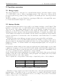
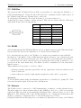
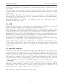
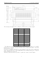
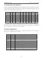
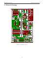
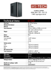
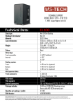
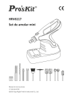
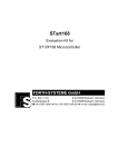
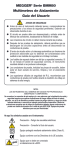
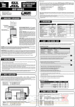
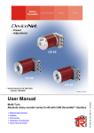
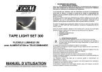
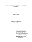
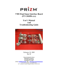
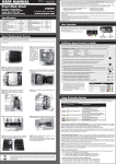
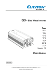
TestBed for mbed
mbed Development System
User Manual
TestBed for mbed
Contents
Contents
1 Introduction
3
2 Function overview
2.1 Energy supply . . . . . .
2.2 Arduino Shields . . . . .
2.3 CAN Bus . . . . . . . .
2.4 RS485 . . . . . . . . . .
2.5 Ethernet . . . . . . . . .
2.6 USB . . . . . . . . . . .
2.7 micro SD card slot . . .
2.8 XBee socket . . . . . . .
2.9 other interfaces . . . . .
2.9.1 Prototyping area
2.9.2 Character LCD .
2.9.3 UART interface .
4
4
4
5
5
5
6
6
7
7
7
7
9
.
.
.
.
.
.
.
.
.
.
.
.
.
.
.
.
.
.
.
.
.
.
.
.
.
.
.
.
.
.
.
.
.
.
.
.
.
.
.
.
.
.
.
.
.
.
.
.
.
.
.
.
.
.
.
.
.
.
.
.
.
.
.
.
.
.
.
.
.
.
.
.
.
.
.
.
.
.
.
.
.
.
.
.
.
.
.
.
.
.
.
.
.
.
.
.
.
.
.
.
.
.
.
.
.
.
.
.
.
.
.
.
.
.
.
.
.
.
.
.
.
.
.
.
.
.
.
.
.
.
.
.
.
.
.
.
.
.
.
.
.
.
.
.
.
.
.
.
.
.
.
.
.
.
.
.
.
.
.
.
.
.
.
.
.
.
.
.
.
.
.
.
.
.
.
.
.
.
.
.
.
.
.
.
.
.
.
.
.
.
.
.
.
.
.
.
.
.
.
.
.
.
.
.
.
.
.
.
.
.
.
.
.
.
.
.
.
.
.
.
.
.
.
.
.
.
.
.
.
.
.
.
.
.
.
.
.
.
.
.
.
.
.
.
.
.
.
.
.
.
.
.
.
.
.
.
.
.
.
.
.
.
.
.
.
.
.
.
.
.
.
.
.
.
.
.
.
.
.
.
.
.
.
.
.
.
.
.
.
.
.
.
.
.
.
.
.
.
.
.
.
.
.
.
.
.
.
.
.
.
.
.
.
.
.
.
.
.
.
.
.
.
.
.
.
.
.
.
.
.
.
.
.
.
.
.
.
.
.
.
.
.
.
.
.
.
.
.
.
.
.
.
.
.
.
.
.
.
.
.
.
.
.
.
.
.
.
.
.
.
.
.
3 Combination of peripherals
10
4 Board configuration
10
5 Technical Drawings
11
2
TestBed for mbed
1
Introduction
1 Introduction
The mbed1768 impressively demonstrates the performance of current 32 bit microcontrollers.
This small controllermodule offers huge possibilities for applications like controlling, metering,
communication and so on. But it can get a challenge connecting the mbed to a bus infrastructure like LAN or CAN. Also the use of a memory card is not as easy as it should be. For these
connection tasks there are many so-called "Breakout Boards" available, most of them with a
single purpose.
Here the TestBed Development System comes into play: It offers a multitude of interfaces
and possibilities for enhancements in combination with the mbed module - ready-to-use and
documented. The arduos composition of necessary hardware (particularly the search for suitable mechanical devices can get exhausting) and the - often rough-and-ready style - assembly
is avoided.
The mbed’s scope of operation increases drastically due to the TestBed compatibility with
Arduino hardware - there ist (nearly) no application without a dedicated Arduino Shield!
Thanks to the enormous calculation power of the Cortex-M3 microcontroller the possibilities
of these shields are boosted to a higher level compared to the original Arduino controllers.
The following functions or components are realised on the TestBed:
• Socket for Arduino Shields
• RS485-Interface
• CAN Bus
• 10/100MBit Ethernet Jack
• mini-USB Connector
• micro-SD Slot
• Miniature Speaker
• XBee Socket
• Socket for Character-LCD
• 2,54mm Prototyping Area
• Backup-Battery for RTC Functionality
• Two Buttons and LEDs as well as one Trim-Potentiometer
• Reset Button
• UART Connector
Following the detail descriptions of the seperate hardware elements. The naming of connectors
and devices are according to the design layout from page 13.
3
TestBed for mbed
2
Function overview
2 Function overview
2.1 Energy supply
The energy supply has to take place by a external mains adapter. It should output a voltage
of 7..9 VDC and be able to deliver a maximum current of 1A. The power connector X2 is
protected agains wrong polarity (voltage is applied to the middle pin, the outer ring holds the
ground).
Another possibility to power the TestBed is connecting an USB cable to the mini USB connector. Please find details in chapter 2.6 on page 6.
2.2 Arduino Shields
As mentioned in the introduction, it is possible to use Arduino hardware on the TestBed. This
hardware comes in the form of so-called shields and are widely available at reasonable prices.
The very most of the existing shields can be used on the TestBed. It must, however, been
taken care of the limitation that TestBed doesn’t supply the shield with 9V - which some
shields need for their operation. Also the mechanical part has to be checked - the shield socket
on the TestBed was designed for the Arduino reference shield. Some shields are larger than the
reference and therefore won’t fit in the socket. If a shield fits on the TestBed has to be verified
in these cases.
Another speciality is the difference in signal voltages between mbed1768 and Arduino:
The mbed1768 uses 3,3V for its GPIO signals whereas the Arduino’s voltage is based on 5V.
As long as there is only digital data transported, there is no problem with that. The mbed’s
GPIOs are tolerant to 5V and the Arduino’s are interpreting input signals of 2V as logical one
(TTL-level).
But when the Arduino shield produces analogue signals the mbed shall sample, it gets a little
complicated. A signal of 3,5V is seen as 70% from the Arduino shield but will be interpreted as
100% by the mbed. This is because the mbed uses a reference (in means of maximum) voltage
of 3,3V. So a circuit is needed to adapt the two voltage domains.
On the TestBed, this circuit is implemented as a simple voltage divider that can be selectively
switched on and off for each of the Arduino’s analogue signals. A set jumper (JP0..JP5) enables
the divider circuit for each of these signals.
Table 1 explains the correspondance between type of signal and position of those jumpers.
signal source
Arduino
Arduino
mbed1768
type of signal
analogue
digital
digital
position of jumper
closed
open or closed
open
Table 1: configuration jumpers of the Arduino interface
This kind of voltage adaption can be used only if the source of the analogue signal is preferably
high-impedance. The plain readout of a potentiometer for example will inevitably result in
failures. This is because the potentiometer acts as a, according to the position of its variable
contact, voltage source of low impedance.
4
TestBed for mbed
2
Function overview
2.3 CAN Bus
The transveicer-IC PCA82C250T from NXP is responsible for connecting the TestBed to a
CAN bus infrastructure. Using JP9 the CAN bus can be terminated with a 120Ω resistor, if
the TestBed is the last resp. the first device on the bus.
To enable the CAN function, JP29 and JP30 have to be set in position 1-2.
A male Sub-D-connector with 9 contacts was used. This is in accordance with the CAN standard which dictates the following pinout:
pin no.
1
2
3
4
5
6
7
8
9
signal name
CAN_L
CAN_GND
CAN_H
-
description
neg. signal
signal ground
pos. signal
-
2.4 RS485
A Texas Instruments SN65HVD3085ED was chosen as RS485 transceiver-IC. When the RS485
bus is needed, the data receive signal has to be enabled by shortening JP7.
For connecting the bus cable to the TestBed a 3-contact screw terminal was used with X6.
Specification of the RS485, being a differential bus system, dictates to use a twisted wire pair
for connecting the bus devices amongst each other. The bus’ ground signal isn’t necessarily to
be connected in cases where the bus devices are sharing the same ground potential (e.g. are
powered from the same mains line). The RS485 should be terminated at both ends with a
suitable resistor.
This termination is necessary to avoid two effects:
• discharge parasitic capacities generated by the two signal wires of the bus and the several
devices on the bus
• reduce reflections caused by high (signal-) frequencies at the ends of open wires
Attention:
To use the RS485 functionality, the miniature speaker has to be disabled by opening JP6. This
is because the mbed signal P21 is used by both functions.
2.5 Ethernet
The TestBed can be connected to a LAN infrastructure or simply to another ethernet device.
The mbed supports comfort features such as Auto-MDIX (no need for so called crossed patch
cables) and Auto-negotiation (automatically determines if the connection has to be 10 or 100
MBit/sec). The ethernet jack on the TestBed includes a set of magnetics (transformers and
chokes), so damages of either the mbed or other LAN devices are avoided.
Using the TestBed in a LAN with power-over-ethernet (PoE) feature won’t destroy the TestBed
5
TestBed for mbed
2
Function overview
or the mbed, although there is no further use of this feature (powering the TestBed via PoE is
not possible).
The transformer’s center taps are connected to the solderpads P1 and P2. This can be useful
to test the behaviour of the ethernet connection when the center taps are connected to certain
voltage levels.
The both signal LEDs built in the ethernet jack can be used if their corresponding jumpers,
JP10 and JP11, are set in position 2-3. Doing so disables the CAN bus, as both functions share
the same mbed signals P29 and P30.
The ethernet shielding is connected to the TestBed’s ground over a 1nF capacitor able to
withstand voltages of up to 2kV.
2.6 USB
Using the mini USB connector, the TestBed can be plugged into a PC USB port. By shorting
JP8 it is possible to supply the board with power from the USB host.
Please note: The current drawn by the TestBed depends on the peripheral configuration and
the program running on the mbed. The USB host must be able to deliver this current otherwise
it can take damage! We suggest using a self-powered USB hub for connecting the TestBed.
Attention: Don’t try to power the TestBed simultaneously by an external mains adapter and
the USB connection! This can cause serial damages to your setup. Always check that JP8 is
open if the TestBed is externally powered and the USB connection is used.
To increase the operating safety, a PTC fuse (F1) was chosen to avoid currents of more than
500mA drawn out of the USB connection. This fuse is self-resetting.
The mini USB connector is intended to allow the usage of the TestBed as an "‘USB device"’. To
use the mbed as "‘USB Host"’ or in the "‘OTG"’ mode, an other type of USB connector should
be used. This connector can be wired to the appropriate mbed signals, USB+ and USB-, by
soldering to X8.
2.7 micro SD card slot
The mbed module offers 512 kB internal and 2 MB externel flash memory but when it comes
to memory, then more is always better. So the TestBed allows the use of micro SD cards to
drastically increase the amount of useable, non-volatile memory. SD cards are cheap and very
common and therefore are the ideal way of adding swappable memory to an embedded system.
The connection to the mbed is done via SPI to consume as few signals as possible. The card
is inserted and taken out by a push-push mechanism. TestBed supports micro SD cards with
a voltage requirement of 3,3V. Micro SDHC (high capacity) cards are not supported.
Attention!
Never attempt to use the TestBed with a plugged micro SD card without external power supply!
Otherwise, the mbed (which is connected to a PC via USB) acts as an power supply trough its
SPI signal pins. Then, current flows trough the SD card’s internal diode to TestBed’s board
supply and the mbed could take damage due to current overload.
The connection to the micro SD card slot is as followed:
6
TestBed for mbed
2
function
CS
MOSI
CLK
MISO
Function overview
mbed signal
P14
P11
P13
P12
2.8 XBee socket
In the last years, the XBee formfactor has developed to a quasi-standard in integrated RFmodules. Therefore, the TestBed comes populated with a XBee socket. So, all modules compatible to XBee can be used as long as they depend solely on the serial connection (RX, TX)
as these two signals are the only connected pins of the XBee formfactor.
This is the pinout of the XBee interface:
function
VCC
DOUT
DIN
GND
XBee signal
1
2
3
10
mbed signal
P10
P9
-
All the other possible XBee signals are unconnected.
2.9 other interfaces
2.9.1 Prototyping area
The prototyping area allows the soldering of small extra circuitry directly on the board. The
solder pads are alligned at a 100mil (2,54mm) grid suitable for most common footprints of ICs.
The area shares its place with an optional LCD or Arduino shield.
On the left side there are the mbed signals P15 to P28, ready to be used in the circuit. On top
and below the solder grid 3,3V, 5V as well as the GND domains are to be found.
To simplify the connection of a self-made data cable to the TestBed, a 2x6 connector (X_OPT)
can be soldered at the right side of the prototyping area. The corresponding solderpads to the
left (TO_X_OPT) can be used to lead the desired signals to the connector.
2.9.2 Character LCD
For visualisation, a standard character display can be attached to the TestBed. Communication takes place using the 4 bit, bidirectional parallel interface. The attachment holes as well
as the position of the 16-pin connector were made according to a fairly common display type
(GDM2004D).
The following dimensional drawing is taken out of the GDM2004D datasheet. It can be used
to check whether the desired LCD will fit onto the TestBed or not.
7
TestBed for mbed
2
Function overview
The following table illustrates the combination of LCD connector and mbed signal.
function
GND
5V
Contrast
RS
R/W
EN
DB0
DB1
DB2
DB3
DB4
DB5
DB6
DB7
Backlight+
Backlight-
LCD signal
1
2
3
4
5
6
7
8
9
10
11
12
13
14
15
16
mbed signal
P26
P25
P24
P23
P22
P20
P19
-
The SMD resistor R41 comes assembled as 4,7Ω. It can absorb a maximum power of 250mW.
It was chosen to work with a yellow/green lit LCD without a built-in series resistor or any other
LCD with such a resistor.
If, however, a backlighted LCD without a series resistance is used, please check carefully if the
value of R41 suits the needs of the backlight LED. If the resulting current gets too high, the
LCD’s backlight will be destroyed!
With the potentiometer R40 it is possible to regulate the contrast of the LC display.
8
TestBed for mbed
2
Function overview
2.9.3 UART interface
X12 was implemented to easily access mbed’s UART signals. The pinout of this connector
matches for example the FTDI USB-to-UART-cable or SparkFun’s FTDI basic adapters.
function
GND
RX
TX
-
X12 signal
1
2
3
4
5
6
9
mbed signal
P27
P28
-
TestBed for mbed
4
Board configuration
3 Combination of peripherals
Caused by the limited GPIO signals available on the mbed, not all of the TestBed’s peripherals
can be used simultaneously. Furthermore, the mechanical dimensions won’t allow to use an
Arduino shield and a LCD at the same time. Information about which peripherals will work
together can be taken from the following table:
uSD
LCD
Arduino
XBee
Ethernet
CAN
RS485
UART
Speaker
uSD
✓
O
✓
✓
✓
✓
✓
✓
LCD Arduino
✓
O
X
X
✓
O
✓
✓
✓
✓
X
O
✓
O
✓
O
XBee
✓
✓
O
✓
✓
✓
✓
✓
Eth. CAN 485
✓
✓
✓
✓
✓
X
✓
✓
O
✓
✓
✓
O
✓
O
✓
✓
✓
✓
✓
✓
✓
✓
X
UART
✓
✓
O
✓
✓
✓
✓
✓
Spkr
✓
✓
O
✓
✓
✓
X
✓
-
An O means that some signals are shared - if the combination will work depends on the
needed functionality. Combinations marked with an X won’t work together. A ✓ signals that
all should be fine. If more than two functions are desired in the application, the combination
has to be manually according to the board’s schematic.
4 Board configuration
The several board functions of the TestBed are configured using jumpers. The following table
lists all of these jumpers and their meanings.
Jumper
JP0
JP1
JP2
JP3
JP4
JP5
JP6
JP7
JP8
JP9
JP10
-"’JP11
-"’-
position
1-2
1-2
1-2
1-2
1-2
1-2
1-2
1-2
1-2
1-2
1-2
2-3
1-2
2-3
function
Arduino analogue signal A0
Arduino analogue signal A1
Arduino analogue signal A2
Arduino analogue signal A3
Arduino analogee signal A4
Arduino analogue signal A5
enable speaker
enable RS485
enable power supply from TestBed’s mini USB connector
enable CAN bus termination
enable CAN bus RX signal
enable ‘Link Active LED’ on ethernet jack
enable CAN bus TX signal
enable ‘Link Speed LED’ on ethernet jack
10
TestBed for mbed
5
5 Technical Drawings
Figure 1: Schematics page 1
11
Technical Drawings
TestBed for mbed
5
Figure 2: Schematics page 2
12
Technical Drawings
TestBed for mbed
5
Figure 3: Board Layout
13
Technical Drawings
TestBed for mbed
5
Technical Drawings
160
150
5
3
5
14
100
90
Figure 4: Mechanical Drawing