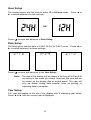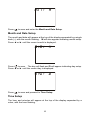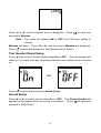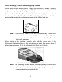
1
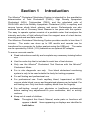
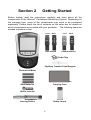
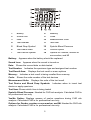
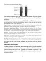
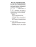
Mission® Cholesterol Monitoring System
Important Safety Instructions
•
If the meter is powered by AC adaptor, unplug the equipment
immediately after use.
•
Misuse of electrical equipment can cause electrocution, burns,
fire and other hazards.
•
Do not place the equipment in liquid, nor put it where it could fall
into liquid. If the equipment becomes wet, unplug it before
touching it.
•
If the meter is powered by AC adaptor, do not leave the equipment
unattended while it is plugged in.
•
Use the equipment only for the purpose described in the
instructions for use.
•
Do not use accessories which are not supplied or recommended
by the manufacturer.
•
Do not use the equipment if it is not working properly or if it has
suffered any damage.
•
Do not let the equipment or its flexible cord come into contact
with surfaces which are too hot to touch.
•
Do not use the equipment where aerosol sprays are being used:
or where oxygen is being administered.
•
Do not use the equipment out of doors.
•
Keep these instructions
ⅰ
Table of Contents
Section 1
Introduction ...........................................................................1 Section 2
Getting Started ......................................................................2 Section 3
Components ..........................................................................4 Meter ........................................................................................................ 4 Test Devices ............................................................................................. 6 Control Devices ........................................................................................ 9 Section 4
Initial Setup ..........................................................................11 Turn on Meter ..........................................................................................11 Coding the Meter.....................................................................................11 Section 5
Meter Setup and Options ....................................................13 Test Number Setup ................................................................................ 13 System Setup ......................................................................................... 14 Section 6
Testing .................................................................................20 Specimen Collection............................................................................... 20 Test Processing ...................................................................................... 26 Section 7
Coronary Heart Disease (CHD) Risk Evaluation ...............29 Section 8
Data/Communication ..........................................................33 Data Transmission ................................................................................. 33 Deleting Data ......................................................................................... 33 Memory/Database .................................................................................. 34 Section 9
Optical System Check ........................................................36 Section 10 Quality Control ....................................................................38 Section 11 Maintenance ........................................................................39 General Cleaning ................................................................................... 39 Disinfection Process ............................................................................... 40 Replacing the Batteries .......................................................................... 41 Section 12
Precautions........................................................................42 Section 13
Troubleshooting ................................................................43 Appendix 1
Meter Specifications ........................................................44 Appendix 2
Index of Symbols .............................................................45 Appendix 3
Warranty ...........................................................................46 ⅱ
Section 1
Introduction
The Mission® Cholesterol Monitoring System is intended for the quantitative
determination of Total Cholesterol (CHOL), High Density Lipoprotein
Cholesterol (HDL), Triglycerides (TRIG), and the calculated ratio of
CHOL/HDL and Low Density Lipoprotein Cholesterol (LDL) in capillary and
venous human whole blood, plasma, and serum. Professionals can also
evaluate the risk of Coronary Heart Disease in ten years with this system.
The easy to operate system consists of a portable meter that analyzes the
intensity and color of light reflected from the reagent area of a test device,
ensuring quick and accurate results.
The Mission® Cholesterol Monitoring System provides results in less than 2
minutes. The meter can store up to 200 results and records can be
transferred to a computer for further analysis using the USB port. The meter
can be operated by 4 AAA (1.5V) batteries or an optional AC adapter.
To ensure accurate results:
•
Read instructions carefully and complete any necessary training before
use.
•
•
Use the code chip that is included in each box of test devices.
Only use the Mission® Cholesterol Test Devices with the Mission®
Cholesterol Meter.
•
For in vitro diagnostic use only. Your blood cholesterol monitoring
system is only to be used outside the body for testing purposes.
•
•
For self testing and professional use.
For professional use: Fresh capillary blood, heparinized or EDTA
venous whole blood, serum and heparinized plasma can be tested. For
self-testing use: Only test fresh capillary blood from the fingertip.
•
For self-testing, consult your physician or healthcare professional
before making any adjustments to your medication, diet, or activity
routines.
•
Keep out of reach of children.
Note:
Throughout this User’s Manual, meter parts or functions will
appear in bold. Items appearing on displays are identified in
bold italics.
1
Section 2
Getting Started
Before testing, read the instructions carefully and learn about all the
components of the Mission® Cholesterol Monitoring System. Depending on
the package type, some of the components may need to be purchased
separately. Please check the list of contents on the outer box for details on
which components are included with your purchase. The following items are
needed to perform a test:
Front
Back
Test Device
Front
Back
Control Device
Code Chip
Capillary Transfer Tube/Dropper
Cholesterol Meter
AAA Batteries
Carrying Case
Sterile Lancets
Lancing Device
Safety Lancet
2
Cholesterol Meter: Reads the test devices and displays the concentrations
of CHOL, HDL, TRIG, and calculated LDL and CHOL/HDL values.
Test Devices: Part of the system, these are inserted into the meter to
measure the concentrations of CHOL, HDL, TRIG and calculated LDL and
CHOL/HDL values.
Code Chip: Automatically calibrates the meter with the code number when
inserted into the meter.
Capillary Transfer Tubes/Droppers: Collects capillary blood from fingertip
blood testing for accurate results (10µL for an individual test and 35µL for a
3-1 test).
AAA Batteries: Provides power for the meter.
Carrying Case: Provides portability for testing.
User’s Manual: Provides detailed instructions on using the Cholesterol
Monitoring System.
Quick Reference Guide: Provides a brief overview of the Cholesterol
Monitoring System and its testing procedures.
Test Devices Package Insert:
Cholesterol Test Devices.
Provides detailed instructions on using the
Lancing Device: Used with sterile lancets to prick the fingertip for blood
specimen collection. The packaged lancing device has multiple depth
settings, allowing users to adjust the depth of the puncture and minimize
discomfort. It can also eject the used lancets.
Lancing Device Package Insert: Provides detailed instructions on how to
use the lancing device.
Sterile Lancets: Used with the lancing device to draw blood specimens for
individual test. Sterile lancets are inserted into the lancing device for each
blood draw and discarded after use.
Safety Lancets: Used to draw blood specimens for 3-1 test and individual
test. Discard after use.
Control Device: Verifies the proper operation of the meter by checking that
the meter can detect a pre-calibrated value.
Control Device Package Insert: Provides detailed instructions on how to
use the Control Devices.
Warranty Card: Card included in the package, which should be completed
and returned to the distributor to qualify for the 2-year meter warranty.
3
Section 3
Components
The Mission® Cholesterol Meter reads the test devices and displays the
concentrations of CHOL, HDL, TRIG, and the calculated value of LDL and the
ratio of CHOL/HDL. Use this diagram to become familiar with all the parts of
the meter.
Meter
1
USB Port
7
Device Channel
2
Liquid Crystal Display (LCD)
8
Test Device Holder
3
Code Chip
9
Position Arrows
4
Right Arrow Button ►
10
Code Chip Slot
5
On/Off Button
11
Battery Cover
6
Left Arrow Button ◄
Meter Display
During testing, the Mission® Cholesterol Meter will display icons showing the
status, options available, and prompts for testing:
4
1
Battery
8
Memory
2
Sound Icon
9
Code
3
Date
10
Measurement Units
4
Test Number
11
Test Item
5
Blood Drop Symbol
12
Systolic Blood Pressure
6
Test Result Area
13
Yes/No Option
7
Test Device Symbol
14
Options for Gender, smoker or
non-smoker, and MI
Appears when the battery should be replaced
Battery:
Sound Icon:
Date:
Appears when the sound is turned on
Shows the current date or date tested
Test Number:
Indicates the specimen type and assigned test number
Test Result Area:
Memory:
Code:
Displays the test result or menu options
Indicates a test result is being recalled from memory
Shows the code number of the test devices
Measurement Units:
Displays the units of the test result
Test Device and Blood Drop Symbols:
device or apply specimen
Indicates when to insert test
Test Item: Shows which item is being tested
Systolic Blood Pressure: Needed for CHD risk analysis. Calculated CHD is
for professional use only
Yes/No Option: Displays answer of yes/no questions during CHD risk
analysis. Calculated CHD is for professional use only
Options for Gender, smoker or non-smoker, and MI: Needed for CHD risk
analysis. Calculated CHD is for professional use only.
5
Meter Use and Precautions
•
•
•
Do not get water or other liquids on or inside the meter.
Keep the Device Channel clean.
Keep the meter dry and avoid exposing it to extreme temperatures and
humidity.
•
Do not drop the meter or get it wet. If the meter is dropped or has
gotten wet, ensure the meter is working properly by running an Optical
Check. Refer to Optical System Check for details.
•
Do not take the meter apart.
warranty.
•
•
Refer to Maintenance for details on cleaning the meter.
Taking the meter apart will void the
Keep the meter and all associated parts out of reach of children.
Note:
Follow proper precautions and all local regulations when
disposing of the meter and used batteries.
All Cholesterol Monitoring Systems Preventive Warnings
with Regard to EMC
1.
This instrument is tested for immunity to electrostatic discharge as
specified in IEC 61000-4-2. However, use of this instrument in a dry
environment, especially if synthetic materials are present (synthetic
clothing, carpets, etc.) may cause damaging static discharges that
may cause erroneous results.
2.
This instrument complies with the emission and immunity
requirements described in EN 61326-1 and EN 61326-2-6. Do not
use this instrument in close proximity to sources of strong
electromagnetic radiation, as these may interfere with proper
operation of the meter.
3.
For professional use, the electromagnetic environment should be
evaluated prior to operation of this device.
Test Devices
The Mission® Cholesterol Test Devices are plastic devices that work with the
Mission® Cholesterol Meter to measure the lipid concentration in whole blood,
plasma and serum.
6
Test device appears as shown below:
Test devices including CHOL Total cholesterol test devices, HDL High Density
Lipoprotein test devices, TRIG Triglycerides test devices and 3-1 Lipid Panel
test device.
3-1 Lipid Panel test devices can detect CHOL, HDL and TRIG with one device
at the same time. The ratio of CHOL/HDL and the value of LDL can also be
calculated by meter at the same time.
Insert Arrow: Located on the front of the test device, the arrows indicate the
direction in which the test device should be inserted into the meter.
Specimen Application Area: After the device is inserted into the Device
Channel, apply the correct specimen volume (10µL for individual test devices
or 35µL for 3 -1 test devices) to the region in the center of the test device.
Handle: Located on the end of the test device, the handle is used to insert
and remove the test device from the meter.
Test Area: Located on the back of the test device. The meter will detect and
read this area to give results of lipid levels.
Position Arrows: Located on the middle position of the specimen application
area. When a test device is inserted, the two arrows should be parallel with the
two arrows on the meter holder to make sure the test device is inserted
correctly.
Specimen Application
For best results, fill the Specimen Application Area with the correct specimen
volume (10µL for individual test devices or 35µL for 3-1 test devices).
Incorrect results may occur if the specimen is not applied correctly or if the
Specimen Application Area is not filled with the correct amount, as shown in
the pictures below.
7
After applying the specimen, ensure that the Specimen Application Area is
completely covered.
The Specimen Application Area should remain covered
throughout the entire test.
If the Specimen Application Area is not covered
or if there is too much specimen covering the Specimen Application Area,
repeat the test with a new test device.
Note:
If the specimen applied to the Specimen Application Area is not
enough, do not add more specimen to the test device. Instead,
retest with a new device. If the E-5 Error or another error
appears on the display, please discard the used device and
retest with a new device.
Code Number
Printed on each package of test devices is a code number
, lot
number
, unopened expiration date, and test quantity . Whenever a
new package is opened, mark the date on the label. Calculate the
expiration date for an opened vial by adding three months. Record this date
on the label.
Test Device Precautions and Instructions for Use
•
Test Devices should be stored in their tightly capped protective canister
or foil pouch to keep them in working condition.
•
Do not store test devices outside of their package. Test devices must
be stored in the original package and sealed tightly.
8
•
•
Do not transfer test devices to a new package or any other container.
Replace the cap on the test device canister immediately after removing
a test device.
•
A new canister of test devices may be used for 3 months after first
being opened. The opened expiration date is 3 months after the date
the canister was first opened. Write the opened expiration date on the
canister label after opening. Discard the canister 3 months after it is
first opened. Usage after this period may result in inaccurate readings.
•
For in vitro diagnostic use. Test devices are to be used only outside
the body for testing purposes.
•
Do not use test devices that are torn, bent, or damaged in anyway.
Do not reuse test devices.
•
Before performing a test, make sure that the code number on the
meter display matches the number shown on the test device canister
or foil pouch and on the ink-jet printing on the code chip.
Refer to the test device package insert for more details.
Control Devices
The Mission® Cholesterol CTRL Control Devices are devices containing a grey
reference pad, which work with the Mission® Cholesterol Meter to ensure the
optical system is working properly. After the control device is inserted into the
meter, the meter’s optical system detects the color intensity of the control
device. The meter displays YES or no to indicate whether the meter is
functioning properly. Refer to Optical System for details.
The control device appears as shown below:
9
Precautions
•
Store in the closed canister at room temperature or in the refrigerator
within 2-30°C (36 – 86ºF). Avoid exposure to direct sunlight, extreme
temperatures, and humidity.
•
Control devices should be stored in their tightly capped canister to
keep them in working condition.
•
•
Do not freeze or refrigerate.
Keep the control devices clean. Do not touch the test area of the
device.
•
Remove the control device for immediate use. Put the control device
back and close the canister tightly immediately after use. Do not use
contaminated, discolored, or damaged control devices.
•
•
Do not use after the expiration date.
For in vitro diagnostic use only.
Storage and Handling
•
Store test devices in a cool, dry place.
direct sunlight.
•
Transport and store in its closed canister within 2-30ºC (36-86ºF) with
less than 90% humidity.
•
•
Do not freeze or refrigerate.
Store away from heat and
Replace the cap on the devices canister immediately after removing a
device. Expired devices may produce incorrect test results.
Note:
The expiration date is printed in a Year-Month format.
For example, 2011-01 is January, 2011.
10
Section 4
Initial Setup
Before testing, ensure the following procedures are followed.
Turn on Meter
The meter can be operated using the certified AC Adapter or 4 AAA batteries
(1.5V).
To use the meter with batteries, insert 4 AAA batteries (1.5V) into the battery
compartment on the back of the meter.
To use the meter with a power adapter, use a USB cable to connect the Mini USB
port of the power adaptor to the USB port on the top of the meter. Then plug the
adaptor into a 100-240V ac, 50-60 Hz primary power outlet.
The meter can also be powered from a personal computer with a USB cable.
OR
The meter will automatically turn on after the batteries are inserted. The
meter will display the date and time setup screen. Refer to Meter Setup and
Options for details. After the date and time have been set, the meter will
automatically turn off.
Press
to turn the meter on. The screen will briefly display all of the LCD
symbols. Observe the LCD at startup to ensure all segments and display
elements are turned on. There should not be missing icons or elements. After
startup, ensure that there are no permanently turned on segments or icons.
After the power-on diagnostic check, the Initial Screen will be displayed.
The meter will automatically turn off after 5 minutes of inactivity.
Coding the Meter
Each time a new box of test devices is used, the new code chip included in
the box must be inserted into the meter. Compare the code number on the
11
code chip from the box with the code number printed on the test device
canister or the foil pouch. Results may be inaccurate if the two numbers are
not identical. Insert the new code chip into the code chip slot of the meter.
It should easily snap into place. The code chip should remain in the meter.
Do not take it out until a new box of test devices is needed. The code
number will appear on the Initial Screen after startup.
If the code chip is not properly inserted into the code chip slot or if it is
missing, the meter will display three dashes as shown below.
12
Section 5
Meter Setup and Options
With the meter turned off, press and hold
Meter Setup mode, shown below.
for 4 seconds to enter the
Press ◄ or ► to display several setup sub-modes:
No. SEt
Test number setup.
CHE
Optical Check mode.
SEt
System setup, including date, time, test number reset, units,
sound, specimen type and CHD.
PC
Data Transfer mode.
dEL
Memory Delete mode.
Elt
Exit setup modes and save changes when
is pressed.
The meter will automatically return to the Initial Screen.
Press
The test number can be set from 1 to 99.
Refer to Optical System Check.
Refer to Data/Communication.
Refer to Data/Communication.
to enter the mode when the desired sub-mode is displayed.
Test Number Setup
From the No. SEt screen, press
to enter Test Number Setup.
13
The test number can be set to any number from 1 to 99.
Press ◄ or ► until the correct test number is displayed.
the desired test number, press and hold ◄ or ►.
Press
To quickly cycle to
to save and return to the Meter Setup screen.
Note:
Once the meter reaches test number 99, the next test number
will be 1.
System Setup
From the SEt screen, press
to enter the System Setup.
Unit Setup
The first option sets the units to either mg/dL or mmol/L. Press ◄ or ► to
switch between the two settings.
OR
14
Hour Setup
The second option sets the clock to either 12 or 24 hour mode.
► to switch between the two settings.
Press ◄ or
OR
Press
to save and advance to Date Setup.
Date Setup
The third option sets the date to Y-M-D, M-D-Y or D-M-Y mode.
► to switch between the three settings.
Press
Press ◄ or
to save and advance to the Year Setup.
Note:
The date in the display will be shown in the form of M-D or D-M
according to the mode you select. However, the year will not
be shown on the display due to limited space. The year will
only be shown during data transfer, such as printing or
exporting data to computer.
Year Setup
The year will appear at the top of the display with Y indicating year setup.
Press ◄ or ► until the correct year is displayed.
15
Press
to save and enter the Month and Date Setup.
Month and Date Setup
The month and date will appear at the top of the display separated by a single
dash (-), with the month flashing. M will also appear indicating month setup.
Press ◄ or ► until the correct month is displayed.
Press
to save. The day will flash and D will appear indicating day setup.
Press ◄ or ► until the correct day is displayed.
Press
to save and proceed to Time Setup.
Time Setup
The hour and minutes will appear at the top of the display separated by a
colon, with the hour flashing.
16
Press ◄ or ► until the correct hour is displayed. Press
proceed to Minutes.
Note:
to save and
The meter will display AM or PM if the 12H time setting is
chosen.
Minutes will flash. Press ◄ or ► until the correct Minutes are displayed.
Press
to save and proceed to Test Number Reset Setup.
Test Number Reset Setup
Press ◄ or ► to turn the test number reset On or OFF. The test number will
reset to 1 for each new day of testing when the test number reset is turned
on.
OR
Press
to save and proceed to Sound Setup.
Sound Setup
Press ◄ or ► to select sound either On or OFF. The Sound Symbol will
appear on the display when the sound is turned on. Press
to save and
proceed to CHD Setup.
17
OR
CHD Setup
Press ◄ or ► to set CHD to either On or OFF. When CHD is set to On, the
meter can enter the Coronary Heart Disease risk evaluation. Press
to
save and proceed to Specimen Type Setup.
For professional use: You can use this function to evaluate the risk of
patients.
This function is not designed for self-testing use. It can only be used by
professionals.
OR
Specimen Type Set Up
Press ◄ or ► to set specimen type to either bL or SE. When specimen
type is set to bL, fresh capillary blood, EDTA or heparinized venous whole
blood can be used. When specimen type is set to SE, serum and heparinized
plasma can be used. Press
to save and return to the setup screen.
18
Note:
bL means Whole Blood, SE means Plasma and Serum.
SE is for professional use only.
Press ◄ or ► until Elt is displayed. Press
to exit the setup. The screen
will briefly go blank and then display the Initial Screen.
19
Section 6
Testing
Before performing any test, the user should review the Mission® Cholesterol
Monitoring System’s User’s Manual for detailed instructions. The following
steps show how to use each component to measure the lipid concentration.
Specimen Collection
•
•
For self-testing, use only fresh capillary blood from the fingertip. Please
refer to Self-Testing on page 20 for details.
For professional testing:
1. Use fresh capillary blood from the fingertip. Please refer to SelfTesting on page 20 for details.
2. Use heparinized or EDTA venous whole blood, serum and
heparinized plasma specimens. Please refer to Professional
Testing below.
Note:
Before testing, choose a clean, dry work surface. Review the
procedure and make sure all of the items needed to obtain a
sufficient amount of blood are available.
Professional Testing (Testing with heparinized or EDTA
venous whole blood, serum and heparinized plasma)
For heparinized or EDTA venous whole blood, serum and heparinized plasma,
Mix the specimen well, then collect specimen (10 μL for individual test, 35 μL
for 3-1 test) into a plastic/glass capillary transfer tubes or pipette. Apply it to
the center region of the Specimen Application Area of the device. Do not
touch the test devices with the pipette or tube.
•
•
•
•
Specimen must be tested within 8 hours of collection.
Mix the specimens well before testing in order to ensure the cellular
components are evenly distributed.
Allow the specimen to come to operating temperature (15-40°C or
59-104°F) for approximately 15 minutes if the specimen has been
refrigerated.
Anticoagulants other than EDTA and heparin are not recommended.
Note:
Refer to NCCLS Documents H3-A6, Collection of Diagnostic
Blood Specimens by Venipuncture.
20
Self-Testing (Testing with fingertip blood)
Wipe away the first drop of blood. Apply light pressure to obtain a second
drop of blood. Collect capillary blood (10 μL for individual test, 35 μL for 3-1
test) using a Capillary Transfer Tube or pipette.
For use with the Capillary Transfer Tube, hold the tube slightly downward and
touch the tip of the Capillary Transfer Tube to the blood specimen. Capillary
action will automatically draw the specimen to the fill line and stop.
Note:
The Capillary Transfer Tube will fill automatically. Make sure
the blood covers the air vent of the tube, or it will be difficult to
squeeze the blood out. Never squeeze the Capillary Transfer
Tube while sampling.
Align the tip of the Capillary Transfer Tube with the center hole of the
Specimen Application Area of the test devices to apply the second drop of
blood (approximately 10 μL for individual test, 35 μL for 3-1 test).
Note:
Do not touch the test device with the Capillary Transfer Tube
or pipette. The capillary blood should be tested immediately
after collected. Use of a Capillary Transfer Tube or pipette is
recommended for accurate results.
21
Blood specimens can be obtained by using a lancing device or a safety
lancet.
Note:
For 3-1 test, please use the safety lancet.
For individual tests, you can use either the lancing device or
the safety lancet.
Lancing Device (For individual tests)
Refer to the instructions below for details.
For obtaining a drop of blood from the fingertip, adjust the penetration depth
on the lancing device to reduce discomfort.
Unscrew the lancing device cover from the body of the lancing device.
Insert a sterile lancet into the lancet holder and push it until the lancet comes
to a complete stop in the lancet holder.
Hold the lancet firmly in the lancet holder and twist the safety tab of the lancet
until it loosens. Then pull the safety tab off of the lancet. Save the safety tab
for lancet disposal.
22
Carefully screw the cover back onto the lancing device. Avoid contact with
the exposed needle. Make sure the cover is fully seated on the lancing
device.
Adjust the puncture depth by rotating the lancing device cover. There are a
total of 6 puncture depth settings. To reduce discomfort, use the lowest
setting that still produces an adequate drop of blood.
Use settings 1 and 2 for delicate skin, 3 and 4 for normal skin, or 5 and 6 for
calloused or thick skin.
Note:
Greater pressure of the lancing device against the finger will
also increase the puncture depth.
Pull the cocking barrel back to set the lancing device. A click may be heard.
The device is now loaded and ready to obtain a drop of blood.
23
Prior to testing, make sure the patient‘s hand is warm and relaxed before
collecting the capillary blood specimen. Use warm water to increase blood
flow if necessary. Massage the hand from the wrist up to the fingertip a few
times to encourage blood flow.
Clean the testing site with an alcohol swab or by washing the hands with
warm soapy water and then dry the testing site thoroughly.
Hold the lancing device against the side of the finger to be lanced with the
cover resting on the finger. Push the release button to prick the fingertip. A
click should be heard as the lancing device activates. Gently massage from
the base of the finger to the tip of the finger to obtain the required blood
volume. Avoid smearing the drop of blood. For the greatest reduction in
pain, lance the sides of the fingertips. Rotation of sites is recommended.
Repeated punctures in the same spot can make the fingers sore and
callused.
24
Note:
Make sure the patient’s hand is warm and relaxed before
collecting a capillary blood specimen. Use warm water to
increase blood flow if necessary.
Don’t use an infection swab containing iodine. This can give inaccurate
results.
Disposal of the Lancet
Unscrew the lancing device cover. Place the safety tab of the lancet on a
hard surface. Carefully insert the lancet needle into the safety tab.
Press the release button to make sure that the lancet is in the extended
position. Slide the ejection button forward to eject the used lancet. Place
the lancing device cover back on the lancing device.
Note:
For professional use, please refer to NCCLS Documents
H04-A6, Collection of Diagnostic Capillary Blood Specimens.
Safety Lancets (For 3-1 test and individual tests)
Carefully rotate and pull off the protective cap.
After cleaning the skin, hold the lancet firmly against the puncture site.
Press the lancet against the puncture site tightly to lance the skin.
the lancet in an appropriate sharps container.
Discard
Gently massage the surrounding area toward the puncture site to collect the
required blood volume.
25
Test Processing
Ensure the meter is set up properly, as described in previous sections. Turn
the meter on. The screen will briefly display all of the LCD symbols.
Observe the LCD at startup to ensure all segments and display elements are
turned on. There should be no missing icons or elements. The meter will
briefly show a blank display. Ensure that there are no segments or icons
permanently turned on.
After startup, the Initial Screen will be displayed. Ensure the code chip is
inserted. Compare the number showed in the display with the code number
printed on the canister label or foil pouch. Refer to Initial Setup. The test
device symbol will flash when the meter is ready for the device to be
inserted.
Check the specimen type displayed on the meter LCD is same as the
specimen type tested. If not, set the correct specimen type. Refer to Section
5 Specimen Type setup.
26
Testing
For use with a test device, insert a device into the Device Channel in the
same direction as the arrows indicate on the device. Ensure that the test
device is inserted all the way to the end of the Device Channel, until the
position arrows are parallel with the two arrows on the Device Holder.
The blood drop symbol will flash when the meter is ready for the specimen
to be applied. Apply the blood specimen (10 μL for individual test, 35 μL for
3-1 test) to the center region of the Specimen Application Area of the test
device.
Note:
For testing capillary blood, use the second drop of blood for
accurate results.
27
The meter will begin testing automatically with three dashes in a line flashing
on the display indicating the test is in progress.
Results will be displayed within 2 minutes. Press ► to view the results.
Note:
The date in the display will be shown in the form of M-D or D-M
according to the mode you previously selected.
Remove the used test device. The meter will return to the Initial Screen and
is ready for another test device to be inserted and to perform a new test.
Note:
Discard all blood specimens, used test devices, and materials
carefully. Treat all blood specimens as if they were infectious
material. Follow proper precautions and obey all local
regulations when discarding blood specimens and materials.
Perform daily cleaning when testing is completed for the day.
Maintenance section.
Refer to the
The meter will automatically turn off after 5 minutes of inactivity or when
is pressed. If the meter is powered with an AC adapter, turn off the meter
before removing it from the power outlet. Remove the batteries if the meter
will not be used for an extended period of time.
28
Section 7
Coronary Heart Disease
(CHD) Risk Evaluation
Note: This function is for professional use only. This function is not for
self-testing use.
If CHD is set to On during setup, the Mission® Cholesterol Monitoring System
can evaluate the risk of Coronary Heart Disease in ten years based on the
test results of a 3-1 test.
In the results screen for LDL, press ► to enter the CHD risk evaluation
screen.
Press
to enter the evaluation method. There are two methods for the
evaluation: FRA and PRO.
FRA (Framingham Heart Study) is popular in United States and is suitable for
both men and women ages 20-79 years old.
PRO (Procam method) is popular in Europe and is suitable for men ages
35-65 years old.
►
◄
Press
to choose the method.
29
If FRA is chosen, Press
to enter the information regarding sex, age,
smoker or non-smoker, Systolic Blood Pressure (SBP), and blood pressure
treatment.
30
If PRO is chosen, Press
to enter the information regarding age, smoker
or non-smoker, Diabetic (DB), Myocardial Infraction (MI), and Systolic Blood
Pressure (SBP).
31
Press
screen.
to enter all the input. The CHD risk ratio will be displayed on the
Press and hold
to return to the testing screen.
According to National Cholesterol Education Program (NCEP), ATP III, 2001,
10-Year risk is defined by three levels:
CHD<10%,
low risk
10%<CHD<20%, medium risk
CHD>20%,
high risk
Results below test ranges will display “<____” and results above the ranges
will display “>____”. When concentrations of specimens are above the test
ranges, values of CHOL/HDL, LDL, and CHD (calculated with PRO method)
will display “- -”. When the concentration of TRIG in the specimen is higher than
400mg/dL, values of LDL will display “- -”.
32
Section 8
Data/Communication
Data Transmission
Plug the USB cable into the USB port located on the top of the meter and
connect the other end of the USB cable to a PC.
Note:
The PC must have a compatible software installed to receive
and process the data transmitted from the meter.
From the Setup screen, press ◄ or ► until PC is displayed. Refer to Meter
Setup and Options for more details. Press
to enable the Data
Communication mode. MEM will be displayed.
Press
to transmit the data to an external certified PC.
After data transmission is complete, the meter will return to the Setup Menu.
Note:
Up to 200 test records are automatically stored in the memory.
After 200 test records are stored, the oldest test record will be
replaced by a new record. For example, if 200 records are
stored in the memory, the next test result (201) will replace the
first result in the memory.
Deleting Data
To delete all data from the meter database, enter the Setup Menu. Refer to
Meter Setup and Options for more details. Press ◄ or ► until dEL is
displayed.
33
Press
to enable data deletion, MEM will be displayed.
Press
until the meter returns to the Setup Menu.
Memory/Database
From the initial test screen, press ◄ or ► to enter the memory/database.
Press ► to enter the EIt screen. Press
34
to return to the testing screen.
Press ◄ or ► to view the memory from corresponding tests: individual or 3-1.
Press
to enter the selected memory screen. The screen will show the
latest results. Press ◄ or ► to choose the No. of results and view each
to
record in the date/time sequence. To view the 3-1 test results, press
enter to the record. Then press ◄ or ► to view results of CHOL, HDL, TRIG,
CHOL/HDL, LDL, and CHD, if the CHD evaluation has been enabled.
Note:
The date in the display will be shown in the form of M-D or D-M
according to the date mode you select.
Press and hold
to return to the Initial Screen.
If no data is stored, the meter will display one dash (-) and MEM.
35
Section 9
Optical System Check
Press ◄ or ► from the Setup Screen to select the Optical Check mode, as
shown below.
Note:
• The control device is intended to check the optical system.
• Allow the control devices and the meter to reach operating
temperature (15-40°C or 59-104°F) prior to testing.
• The optical check should be performed under normal lab lighting
conditions. Do not perform under sunlight or extreme lighting
conditions.
to enter this mode.
Press
as shown below.
The meter will flash the test device symbol,
Insert a control device into the Device Channel. Follow the direction of the
arrows indicated on the device. Ensure that the control device is inserted all
the way.
Press
normal.
to start the optical check. If the meter displays YES, the meter is
If the meter displays no, the meter is not functioning properly.
36
OR
If the meter displays no, check the control device for contamination or to
check if it is damaged. If there are any visible signs of damage or
contamination, discard the control device and retest using a new device.
Press
to return to the Setup Screen.
37
Section 10
Quality Control
Each lab should use its own standards and procedures for performance.
Test known specimens/controls at each of the following events in accordance
with local, state, and/or federal regulations or accreditation requirements:
•
•
•
•
•
Each new day of testing
When a new package of test devices is opened
When a new operator uses the meter
When test results seem inaccurate
After performing maintenance or service on the meter
If QC tests do not provide expected results, perform the following checks:
•
•
•
•
Ensure that the test devices used are not expired.
Ensure that the test devices are fresh from a new canister or package.
Ensure that the controls are not expired.
Repeat the test to ensure no errors were made during the test.
38
Section 11
Maintenance
Proper maintenance is recommended for best results.
General Cleaning
For best results, the meter should be cleaned after each day of testing.
Meter Surface
A cotton cloth can be used to clean the surface of the meter.
cotton cloth if necessary.
Use a damp
A dry, soft cloth may be used to clean the LCD and the sensor area. It is
recommended that the meter be stored in the carrying case after each use.
Avoid getting liquids, residue, or control solutions in the meter through the
Device Channel, Code Chip Slot, or USB Port.
Test Device Holder
Remove the Test Device Holder by pressing in on the middle of the Test
Device Holder and sliding it out from the meter. Wipe it down with a damp
cloth or a mild detergent. Dry it with a dry, soft cloth. Slide the Test Device
Holder back into the meter by laying it flat on the meter. Firmly press down
on the two sides of the Test Device Holder with your thumb and push it in
until it clicks into place.
Note:
Do not use organic solvents, such as gasoline or paint thinner.
This will cause damage to the meter.
Meter Sensor Area
Remove the Test Device Holder as described in the previous section.
Wipe down the Meter Sensor Area with a cotton swab. Do not scratch the
transparent window covering the sensors.
39
Note:
Do not use bleach or alcohol to clean the Meter Sensor Area.
This will cause damage to the meter.
Disinfection Process
The disinfection process should be performed before each test to prevent
potential infectious disease transmissions through bloodborne pathogens.
Cleaning Before Disinfection and How to Disinfect
Before disinfection, use EPA Registered towelette/wipes with active
ingredients of Isopropyl alcohol to clean the meter. Use these towelette/wipes
to remove any stains/debris. The cleaning before disinfection ensures stains
or debris are removed before disinfection for an effective sterilization.
For disinfection, please use a fresh EPA Registered towelette/wipe with
active Isopropyl alcohol to wipe the meter. Be sure to wet the entire outer
meter surface thoroughly. The outer meter surface must remain visibly wet for
one full minute. After wiping, allow the meter to air dry completely before
using the meter again.
Note: Avoid inserting the towelette/wipe into the inside of the Code
Chip Slot and the USB Port when performing cleaning before
and during disinfection.
Disinfection Frequency
The meter disinfection process should be performed for the first 2 years of
the meter usage. This ensures that your meter will operate properly with
regular disinfection for the first 2 years of the meter’s life. Check normal
meter electronic operations regularly. Do this by ensuring the LCD display
shows all segments once the meter is turned on before testing.
40
Replacing the Batteries
When the battery icon
is flashing, the batteries
are low and should be replaced as soon as possible.
An E-4 error message will appear if the batteries are
too low to perform any more tests. The meter will not
function until the batteries are replaced.
Make sure the meter is off before removing the batteries. Turn the meter
over to locate the battery cover. Press the battery cover tab on the top and
lift the cover to open it. Remove and discard the old batteries. Insert four
new AAA batteries into the battery compartment, alternating orientation up
and down as indicated in the bottom of the battery compartment.
Close the battery cover and make sure that it snaps shut. Recheck and
reset the clock setting if necessary, after replacing the batteries to ensure that
the time is correctly set. Refer to Initial Setup.
Note:
Do not discard batteries with household waste.
regulations for disposal.
41
Follow local
Section 12
Precautions
Follow the precautions listed below to ensure accurate results and proper
operation of the meter.
•
The protection provided by the equipment may be impaired if used in a
manner not defined in this instruction manual.
•
Wear gloves to avoid contact with potentially hazardous biological
specimens during testing.
•
Avoid storing or operating the meter in direct sunlight, excessive
temperatures, or high humidity.
Refer to Appendix 1 Meter
Specifications for operating condition requirements.
•
Keep the unit clean. Wipe it frequently with a soft, clean, and dry
cloth. Use a damp cloth when needed.
•
Do not clean the unit with substances, such as gasoline, paint thinner
or other organic solvents to avoid any damage to the meter.
•
Do not clean the LCD or sensor area with water.
soft, clean, dry cloth.
•
The device channel must be kept clean. Lightly wipe with a soft,
clean, dry cloth each day. Use a damp cloth as needed. Refer to the
Maintenance section.
•
•
Follow all local regulations when discarding the unit or its accessories.
Lightly wipe with a
Do not use the unit or the devices outside of the operating temperature
ranges: 15-40°C (59-104°F); ≤ 90% RH.
42
Section 13
Display
Troubleshooting
Causes
Solution
Ensure the sensor area is clean and that
The sensor area is damaged,
there are no objects covering the sensor
dirty, or blocked at turn-on, such
area. Refer to Maintenance. Restart
as a used test device left in the
the meter. Contact your local distributor if
meter.
the sensor area window is broken.
Test device was
during the test.
removed Repeat the test and ensure the test device
remains in place.
Specimen was applied to the Repeat the test and apply specimen after
test device too soon.
blood drop symbol appears.
Batteries are discharged but
have enough power to run 20
more tests.
Batteries are low and meter will
not allow more tests until the
batteries are replaced.
Test results will still be accurate, but replace
the batteries as soon as possible.
Replace the batteries, or connect the meter
to the AC Adapter, then repeat the test.
Insufficient specimen.
Repeat the test. Apply enough specimen.
Use around 10 μL (for individual tests) and
35 μL (for 3-1 test) of specimen.
Expired test device.
Ensure the test devices are within the
expiration date printed on the package label.
Insert proper code chip. Confirm the
Code chip was removed during
code chip matches the test device code
testing.
and repeat the test.
The test device type does not Use the proper device which its type
match the code chip.
matches the code chip.
The environment temperature is
Get the meter in a proper environment
higher than 40 ºC (104ºF)
where the temperature is between 15The environment temperature is
40ºC (59 -104ºF)
lower than 15 ºC (59ºF)
Insert the code chip that accompanied the
package of test devices.
No code chip in the meter.
If the code chip is damaged, use a new
Code chip is damaged or
code chip with the correct code number.
inserted incorrectly.
If the code chip is inserted incorrectly,
remove the code chip and insert it into the
code chip slot.
43
Appendix 1
Meter Specifications
Feature
Specifications
Methodology
Reflectance Photometer
Test Time
≤ 2 min
Measurement
Range
CHO: 100-500mg/dL (2.59-12.93 mmol/L,1mmol/l=38.66mg/dL )
HDL: 15-100 mg/dL (0.39-2.59 mmol/L, 1mmol/l=38.66mg/dL)
TRIG: 45-650 mg/dL (0.51-7.34 mmol/L, 1mmol/l=88.6mg/dL)
Specimen
Whole blood, plasma, and serum
Specimen
Volume
10 μL for individual test; 35 μL for 3-1 test.
Power Source
4 AAA batteries (1.5V)
AC Adapter (Mini USB, 5V dc, 50 mA)
Battery Life
85 hours or 1,000 tests
Units of
Measurement
mg/dL, mmol/L
Memory
200 records
Automatic
Shut Off
5 minutes after last use
Meter Size
137 mm × 79 mm × 26 mm (5.4” × 3.11” ×1.02”)
Display Size
50 mm × 50 mm (1.97” ×1.97”)
Weight
145g (without batteries)
Meter Storage
Conditions
0 - 50ºC (32 -122ºF); ≤ 90% RH
Operating
Conditions
15 - 40ºC (59 -104ºF); ≤ 90% RH
Meter
Connectors
USB cable for Data Transfer or Power (optional)
44
Appendix 2
Index of Symbols
Consult instructions
For in vitro
diagnostic use only
for use
REF
SN
Catalog #
Serial Number
Authorized
Manufacturer
Representative
Lot Number
Use by
Contains sufficient for
<n> tests
Store between
2-30°C (36 - 86ºF)
Sterilized using
irradiation
Code Number
Do not discard along
with household waste
USB Port
Fragile, handle with care
This Side Up
Keep away from sunlight
Keep Dry
and heat
MODEL
Do not reuse
45
Model number
Appendix 3
Warranty
Please complete the warranty card included in the packaging.
distributor to register your purchase within 30 days of purchase.
Mail it to your local
For your records, write the purchase date of your starter kit here:
Note: This warranty applies only to the meter in the original purchase.
apply to the other materials included with the meter.
It does not
ACON Laboratories, Inc. warrants to the original purchaser that this meter will be free
from defects in materials and workmanship for a period of two years (24 months). The
two years starts from the later of the date of original purchase or installation, except as
noted below. During the stated two year period, ACON shall replace the meter under
warranty with a reconditioned meter or, at its option, repair at no charge a meter that is
found to be defective. ACON shall not be responsible for shipping charges incurred in
the repair of a meter.
This Warranty is subject to the following exceptions and limitations:
This warranty is limited to repair or replacement due to defects in parts or workmanship.
Parts required which were not defective shall be replaced at additional cost. ACON
shall not be required to make any repairs or replace any parts that are necessitated by
abuse, accidents, alteration, misuse, neglect, failure to operate the meter in accordance
with the user’s manual, or maintenance by anyone other than ACON. Furthermore,
ACON assumes no liability from malfunction or damage to meters caused by the use of
devices other than devices manufactured by ACON. ACON reserves the right to make
changes in the design of this meter without obligation to incorporate such changes into
previously manufactured meters.
Disclaimer of Warranties
This warranty is expressly made in lieu of any and all other warranties expressed or
implied (either in fact or by operation of law), including the warranties of merchantability
and fitness for use, which are expressly excluded, and is the only warranty given by
ACON.
Limitations of Liability
In no event shall ACON be liable for indirect, special or consequential damages, even if
ACON has been advised of the possibility of such damages.
For warranty service, please contact your local distributor.
46