1
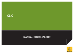
BTEL-GT I G E F Manuale di installazione ed uso Installation and User Manual Manual de instalación y usuario Manuel d'installation et d'utilisation ISO 9001 9105.BNT1 ISO 9001 IT-52587 0470 ISO 14001 9191.BNT2 ISO 14001 IT-52588 OHSAS 18001 OHSAS 18001 9192.BSEC IT - 60983 Tab.1 I IDENTIFICAZIONE E DESCRIPCION DE G PARTS F IDENTIFICATIONS N. DELLE PARTI LOS COMPONENTES DESCRIPTION DES PIECES Viti (4) per il fissaggio del Screws (4)to fix the cover Tornillos (4) para fijar la tapa del Vis (4) pour la fixation du 1 coperchio al fondo to the backplate fondo couvercle au fond 2 Coperchio Cover Tapa Couvercle 3 Griglia per microfono Microphone grill Parrilla para micrófono Grille pour microphone 4 LED di controllo Status LEDs LED de control LED de contrôle 5 Fondo Backplate Fondo Fond Fori (4) per il fissaggio del Holes (4) for backplate Orificios (4) para fijar fondo Trous (4) pour la fixation du fond 6 fondo (Ø 5 mm) mounting (Ø 5 mm) (Ø 5 mm) (Ø 5 mm) Altoparlante per la Speaker for message Altavoz para la reproducción de Haut-parleur pour la reproduction 7 riproduzione dei messaggi playback mensajes des messages Deviatore antistrappo Wall tamper switch Desviador Antiarrancamiento Déviateur Anti-arrachement 8 (opzionale) (optional) (opcional) (optionnel) 9 Foro per vite antistrappo Hole for wall tamper screw Orificios para tornillo antiarranque Trou pour vis anti-déchirement Apertura, sul fondo, per il Cable feed opening on Abertura en la base para el Ouverture, sur le fond, pour le 10 passaggio dei cavi the base paso de los cables passage des câbles Cavetti per il collegamento Conectores para la conexión Câbleaux pour le branchement de 11 Battery connectors della batteria tampone del acumulador la batterie de secours Alloggiamento per una Compartment for a Logement pour une batterie de Asiento para un acumulador de 12 batteria tampone da 12V / 1.2 Ah battery secours de 12 V / 1,2 Ah (non 12 V / 1,2 Ah (no en dotación) 12 V / 1,2 Ah (non fornita) (not provided) fournie) 13 Tastiera alfanumerica Alphanumeric keypad Teclado Alfanumérico Clavier alphanumérique 14 LED di controllo Status LEDs LED de control LED de contrôle Microfono per la Microphone for recording Micrófono para grabar Microphone pour l'enregistrement 15 registrazione dei messaggi messages mensajes des messages 16 Deviatore antisabotaggio Tamper switch Desviador antisabotaje Déviateur antisabotage Connettore cavo per Cable connector for the Conector cable para la Connecteur câble pour la mise à 17 l'aggiornamento firmware firmware update actualización del firmware jour firmware 18 Connessione per altoparlante Speaker connection Conexión para altavoz Connexion pour le haut-parleur Ponticello per l'impostazione Jumper for setting Puente para programación de Cavalier pour le réglage de la della polarità di attivazione: activation mode: la polaridad de activación: polarité d'activation: Attivazione con segnali positivi (Positivo a dare o positivo a mancare - DEFAULT) UP o Activated by positive signal (positive command or positive drop - DEFAULT) O DOWN O Activación con señales positivas (Positivos presente y positivo ausente - DEFAULT) 19 Activation avec signaux positifs (présence ou absence - DEFAULT) Attivazione con segnali negativi (Negativo a dare o negativo a mancare) UP O Activated by negative signal (negative command or negative drop) O DOWN o Activación con señales negativas (Negativo presente y negativo ausente) Activation avec signaux négatifs (présence ou absence) Connettore per il collegamento Conector para la conexión de la Connecteur pour le branchement de 20 Battery connector batería la batterie de secours della batteria tampone Morsettiere per i Regleta de terminales para las 21 Terminal Blocks Bornier pour les branchements collegamenti conexiones 22 Porta SIM CARD SIM holder Porta-SIM Port SIM Tab.2 CARATTERISTICHE TECNICHE Tensione di alimentazione TECHNICAL FEATURES Input Voltage ESPECIFICACIONES TECNICAS Tensión de alimentación CARACTÉRISTIQUES TECHNIQUES Tension d'alimentation Corrente a riposo: Comunicatore Uscite (se collegate) Standby current: Communicator Outputs (if connected) Corriente en reposo: Comunicador Salidas (si conectadas) Courant au repos: Transmetteur Sorties (si reliées) 13.8 V_ ±2% 500 mA 100 mA massimo 400 mA máximo Corrente in allarme (trasmissione): Alarm (Transmitting) current: Corriente en alarma (transmisión): Courant en alarme (transmission): 600 mA maximum Comunicatore Communicator Comunicador Transmetteur 200 mA Uscite (se collegate) Outputs (if connected) Salidas (si conectadas) Sorties (si reliées) 400 mA Uscite OC Open collector outputs Salidas OC Sorties OC 4 open collector, da 100 mA Solo per applicazioni interne Indoor Application only Caractéristiques Caratteristiche ambientali Environment Características ambientales Sólo para aplicaciones internas environnementales Uniquement pour utilisation en intérieur 5 °C ÷ 40 °C Temperatura de Température de Temperatura di funzionamento Operating Temperature 5 °C to 40 °C funcionamiento fonctionnement (41 °F to 104 °F) 93% (senza condensa) 93%RH Non Condensing Umidità relativa Humidity Humedad relativa Humidité relative 93% (sin condensación) 93% (sans vapeur) Dimensioni (L x A x P) Dimensions (W x H x D) Dimensiones (An x Al x P) Dimensions (H x E x L) 132x220x62 mm Peso (senza batteria) Weight (without battery) Peso (sin batería) Poids (sans batterie) 449 g 1 1 5 6 2 6 7 I 3 4 G E 8 9 11 10 12 6 1 1 14 13 6 15 18 16 17 19 20 22 21 22 RS-232 2 3 5 1 4 Connettore 17 1 2 3 4 5 6 7 8 9 10 11 12 13 +OC Fig. 1 - Parti - Parts - Componentes - Composants F Tab. 3 - Codici Operatori, Operator Codes, Códigos Operadores, Codes Opérateurs. Tabella codici operatori Table of Operator Codes Tabla Códigos Operadores Tableau des codes opérateurs Nazione Country País Pays Italia Italy Italia Italie Spagna Spain España Espagne Belgio Belgium Bélgica Belgique Codice Code Código Code Operatore Operator Operador Opérateur 22201 TIM 22210 Vodafone 22288 Wind 21401 Vodafone 21403 21409 Orange 21407 Movistar 20601 Proximus 20610 Mobistar 20620 Base 20800 20801 Francia France Francia France Orange 20802 20810 SFR 20820 20821 Bouygues 20888 Portogallo Portugal Portugal Portugal 4 26801 Vodafone 26803 Optimus 26806 TMN BTEL-GT TABLE OF CONTENTS INTRODUCTION 25 INSTALLATION 26 CONNECTING THE DEVICE 27 STATUS LEDS OPERATING PRINCIPLES 28 29 PROGRAMMING PROGRAMMING BY KEYPAD 29 30 General Features 25 Mounting 26 Activation Polarity 27 Priority management 29 Restore Factory Settings Access to Programming Mode Parameters Management 31 31 31 Phone Book Management .................................................... 31 Write Phone Book .................................................................. 31 Read Phone Book ................................................................. 31 Delete ..................................................................................... 31 Voice Messages Management .............................................. 32 Listen to Voice Messagge ..................................................... 32 Record Voice Message .......................................................... 32 Management Options Calls ................................................... 32 Call Handling on Input .......................................................... 32 Management Repetitions of Voice Messages ...................... 33 Management Call Cycles ....................................................... 33 Management Call All .............................................................. 33 Management Call Confirm Result ......................................... 33 Advanced Management ........................................................ 34 Management Input Polarity ................................................... 34 Periodic Message ................................................................... 34 Language change ................................................................ 34 Set Date and Time ................................................................ 34 Output Management ............................................................. 34 Output Type Management .................................................... 34 Output Polarity Management ................................................ 35 Output Caller Recognition Enable ........................................ 35 Confirm Output Activation Enable ......................................... 35 Available Networks Management Installer Code 35 35 Input Activation 36 REMOTE PROGRAMMING BY TEXT MESSAGE 36 Low Battery Power Message ................................................ 36 Periodic Message Pay As You Go Balance 36 37 UPDATE THE FIRMWARE USER 37 38 Programming by keypad Remote programming 38 38 Dialer Parameters Management ........................................... 39 Output Management ............................................................. 39 Monitor Input .......................................................................... 39 Environment Listen Management ......................................... 39 Block Calls ............................................................................... 39 Change Code ........................................................................ 39 Dial Number ............................................................................ 39 Phone Book Management .................................................... 40 Write Phone Book .................................................................. 40 Read Phone Book ................................................................. 40 Delete ..................................................................................... 40 Superkeys ............................................................................... 40 Remote Programming by text message 40 Output Management ............................................................. 40 Bistable Output ....................................................................... 41 Monostable Output ................................................................ 41 Pay As You Go ........................................................................ 41 Expiry date of the SIM card ................................................... 41 Activate the Outputs via Caller Identification ........................ 41 Hereby, Bentel Security declares that the BTEL-GT is in compliance with the essential requirements and other relevant provisions of Directive 1999/5/EC. The complete R&TTE Declaration of Conformity for each Device can be found at www.bentelsecurity.com/dc.html. Installation of these systems must be carried out strictly in accordance with the instructions described in this manual, and in compliance with the local laws and bylaws in force. The above mentioned BTEL-GT has been designed and made to the highest standards of quality and performance. The manufacturer recommends that the installed system should be completely tested at least once a month. BENTEL SECURITY srl shall not be responsible for damage arising from improper installation or maintenance by unauthorized personnel. BENTEL SECURITY srl reserves the right to change the technical specifications of this product without prior notice. G Recycling information BENTEL SECURITY recommends that customers dispose of their used equipments (panels, detectors, sirens, and other devices) in an environmentally sound manner. Potential methods include reuse of parts or whole products and recycling of products, components, and/or materials. For specific information see: www.bentelsecurity.com/index.php?o=environmental Waste Electrical and Electronic Equipment (WEEE) Directive In the European Union, this label indicates that this product should NOT be disposed of with household waste. It should be deposited at an appropriate facility to enable recovery and recycling. For specific information see: www.bentelsecurity.com/index.php?o=environmental 24 BTEL-GT INTRODUCTION The BTEL-GT is a telephone dialler that can call a series of preset phone numbers, to which it can send both voice alarms and text messages. The BTEL-GT is available in an ABS plastic container which is placed inside the alarm system it is connected to. The plastic box is protected against tampering (unauthorized openings) and tearing (optional). The BTEL-GT does not require any software to set its various options and data, but it can be programmed completely using an alphanumeric keyboard and a voice menu that can be heard through the speaker on the baseplate.The BTELGT is compatible with all alarm systems and Bentel systems belonging to the NORMA8/NORMA4, KYO, and ABSOLUTA series. The BTEL-GT's performance depends particularly on GSM network coverage; therefore, it should not be installed before testing several positions to get the best location for reception (at least one green LED should be on). For optimal installation, search for the operator with the strongest signal. The BTEL-GT is equipped with: – 4 programmable alarm inputs. When the input is activated, the dialler can send voice and text messages to up to 9 numbers. – 4 OC (Open Collector) type outputs, 3 of which can be programmed and managed either on-site with a keyboard or remotely via DTMF and SMS, while 1 output is reserved for signaling malfunctions (problems with the GSM network or low battery). The BTEL-GT can store 9 telephone numbers of up to 16 digits each. Voice messages can be recorded directly on the dialler using an internal microphone and played back through a speaker on the baseplate (the microphone and the speaker are also used for the live function). This manual provides programming and operation of the telephone dialler. This Device is fixed and shall be installed by Service Persons only (service person is defined as a person having the appropriate technical training and experience necessary to be aware of hazards to which that person may be exposed in performing a task and of measures to minimize the risks to that person or other persons). It shall be installed and used within an environment that provides the pollution degree max 2, over voltages category II, in nonhazardous, indoor locations only. This manual shall be used with the Installation Manual of the alarm control panel. All instructions specified within that manual must be observed. General Features Voice menu in 4 languages for programming and use. 4 programmable input lines. Up to 3 voice messages can be associated with each event: 8 messages lasting up to 8 seconds each. Checking on the remaining credit for pre-paid SIM-cards. Open microphone function. Speakerphone function. Sending of voice and text messages to activate input. Alarm call activation can be programmed with commands and programmable polarity options (positive or negative). 9 telephone numbers (up to 16 digits each) can be programmed. Protection from accidental inversion of battery polarity. Battery and network coverage monitoring. Programmable by voice and with a keyboard. 1 OC (Open Collector) output reserved for announcing malfunctions. 3 programmable OC (Open Collector) outputs. 6 signal LED's. GSM Quad-Band. Internal antenna. GSM Telephone dialler Remote output activation through caller recognition and/or by sending a text message. Memory of alarm inputs for handling multiple sends. Priority for input n.1. A fourth input can be programmed to block call cycles. Remote call cycle blocking. The number of times to attempt a call can be programmed. The number of repetitions for an alarm message can be programmed. Searches for the operator with the best GSM coverage. Time and date programming. Periodic voice message. Periodic text message. Low battery indicated by text message. Microphone for recording messages and the live function. Speaker for listening to recorded messages and speakerphone function. Superkey management. Digital recording and playing of messages. Protection from attempts at sabotage (protection against opening and tearing). Housing for a 12 V - 1.2 Ah battery (not supplied). 25 G INSTALLATION Do not route any wiring over circuit boards. This Device shall be installed by qualified SERVICE PERSONS only, in the shelter of a safe and dry site, away from radio-transmitting equipment. Test the GSM Network reception before mounting this Device in the proposed placement. Mounting This paragraph describes how the BTEL-GT is installed. Numbers in bold type between square brackets refer to the parts in Fig. 1, unless indicated otherwise. 1. Remove the cover by unscrewing the four screws [1]. 2. Mark the position of the holes [6] required to fix the metal base [5] to the wall. 3. Drill holes in the wall as marked. ! Check for cable conduits and water pipes before drilling. 4. Pass the connection cables through the opening on the base [10]. 5. Fix the metal base to the wall using wall anchors (not supplied). 6. If necessary, assemble the Wall Tamper Switch (optional) [8] as shown in Figure 1. The switch lever must be directed as illustrated in Figure 1, otherwise the device will not work correctly. 7. Arrange the connections to the terminal box [21] as described in the section “Connecting the device”. 8. Connect the connector [20] to the battery with the wire [11]. ! Use only batteries sealed. Connect the terminals of the tamper switch [16] (see the section "Connecting the device") to the tamper line or to an appropriate area of the alarm system. Read the instructions for the alarm system for further information. After the BTEL-GT is installed, it may be necessary to remove the front panel for maintenance or repair purposes. Bear in mind that if the tamper switch [16] is connected to the corresponding line of an anti-intrusion system, the latter can cause an undesired alarm. Therefore, before removing the front panel of the BTEL-GT, make sure that the panel's alarm group is disabled (refer to the control panel's instructions for information on how to disable the alarm group). 9. Following the arrow, insert the SIM-CARD face down in the SIM holder [22] (see Figure 1). The PIN for the SIM CARD must be disabled before inserting it in the SIM holder. 10. When you turn it on, check whether all the green LED's are blinking; in this case, the BTEL-GT is initializing. 11. Checking Signal Strenght : – make sure that at least one of the green LEDs remains lit; all green LEDs lit indicates optimal coverage; – if the green LEDs are not illuminated, the signal strength is TOO WEAK; change the position of the antenna until you find a position which offers acceptable signal strength, at least one LED illuminated. 12. Close the BTEL-GT: place the cover [2] on the baseplate [5]; fix the cover by tightening the screws [1]. Close the control panel cover. ! Before inserting or removing the SIM card, please ensure the unit is powered down. 26 BTEL-GT CONNECTING THE DEVICE This section describes the various terminals. Figure 3 shows a typical wiring diagram. N. Terminals 1 +12 Description Power supplied by the control unit or by the external power supply ADP1512 (optional), 13,8 Vcc ± 2%, make sure that this is protected and operating at a limited current; Limited Power Source (LPS) in conformity with EN 60950-1:2006 standard. ! To connect the supply use wires with a maximum 2 mt length and 0.75mm² cross-section. For shorter wires use suitable cross-sections. 2 3 4 M 5 +OC all Outputs O1, O2, O3 and O4. AS Negative: Power Supply. Tamper switch: These terminals are connected serially to the tamper switch [ 16] and are closed when the cover [2] of the dialler is completely closed; they open when the cover [2] is removed. Common terminal for Open-Collector Outputs: Common power-supply terminal (12 VDC / 100 mA) for 6 O1 7 O2 8 O3 9 O4 Open-Collector output: This output is activated by GSM network malfunctions, low battery power, and problems with the SIM card. 10 M Negative: Power Supply. 11 L1 12 L2 13 L3 14 L4 15 M Open-Collector Programmable Output Ports: these output ports can be activated from a voice menu (local or remote), or else either by sending a command in a text message or through caller ID (Remote Activation). The maximum current that can be drawn from each OC output port is 100 mA. Input lines: When these inputs receive alarm signals, they can activate the SMS and telephone dialer function. Negative: Power Supply. ! The Open Collector current may not exceed 100 mA. If necessary, commutate greater loads using switches or our switch boards BRM04/12 (12V dc) and BRM04/24 (24V dc). Activation Polarity The Dialler contains 4 alarm inputs; each input can be activated by signals with positive or negative polarity; in the factory, the dialler is programmed to be activated by signals with positive polarity. To set the activating polarity, see Table 4. Table 4 - POLARITY AND ACTIVATION Activation command for input channels Jumper [19] Negative drop (fail-safe) O UP O o DOWN Negative command Positive drop (fail-safe) Positive command GSM Telephone dialler o UP O O DOWN Settings Programming Input Polarity (positive) (negative) (negative) (positive) 27 G 1 2 3 4 5 6 7 8 9 10 11 12 13 14 15 +OC Relay Power Supply 13.8 Vdc ±2% Tamper line of the security system WARNING Incorrect connections may result in FTC fault or improper operation. Inspect wiring and ensure connections are correct before applying power. DO NOT route any wiring over circuit boards; maintain at least 1” (24.5 mm) separation. A minimum 1/4” (6.4 mm) separation must be maintained at all points between Power Limited wiring and all other Non-Power Limited wiring. Fig. 3 - Example of connection to the BTEL-GT dialler STATUS LEDS On the screen there are 6 LED's; three green LED's, one red LED, one yellow LED, and one red LED, which show connection, malfunctions, transmission, the status of the BTEL-GT, and programming mode. During inizialization, the LED's will flash. GREEN — The three green LED’s show the strength of GSM reception and status (table 5): The first LED, if ON, shows optimal GSM reception: therefore, it turns on only when the second and third LED's are also lit. The second LED. When this LED is ON, the reception is good: this LED turns on only when the third green LED is lit; The third LED, if turned OFF, indicates that the GSM network is NOT available. If this LED is lit, the network signal is low but sufficient for voice calls; RED — This LED is normally OFF. If it lights up, this indicates a malfunction. The BTEL-GT checks for tthe presence of some malfunctions (for example, no GSM network or low battery power); the red LED will remain lit until the malfunction is repaired. YELLOW - If ON it means a call (either incoming or outgoing) is taking place on the GSM network. RED - If solid lit it indicates that factory data are being loaded or programming is under way. 28 BTEL-GT BTEL-GT dialler status indication LED flashes Intermittently Continuously (flashes ON/OFF twice in (500ms ON/OFF) 500ms, then OFF for 2 seconds) Meaning — Problem with the SIM card — G The dialer is initializing; flash until a GSM signal is received Fig. 5 - Indications of the dialers status from the Green LED's. OPERATING PRINCIPLES Once the language is selected, the voice menu for programming will become active in the language chosen. The interface language can also be changed, either from a menu in the corresponding section or by using a keypad sequence (see section "Advanced Management->Language change"). This also allows the device to be programmed in one language and then operated in another one. When the device is turned on, no voice or text messages are sent until the radio module is completely initialized. Any input activation will be ignored. If the dialler is not capable of performing the command associated with the activation of an input, the command will be memorized and executed when the device returns to being ready, which allows for the handling of multiple messages due to the simultaneous activation of multiple inputs. For optimal installation of the device, search for the operator with the best coverage. Priority management The BTEL-GT can send voice and text mesages. Text messages have a higher priority compared to voice messages. If at the end of a voice message, there are text messages to be sent with the activation of another input, the latter are sent before any other voice mesages. IMPORTANT - Input no. 1 (L1) takes priority over the other inputs: if input no. 1 (L1) is activated, the call cycles related to it are carried out, even if at that moment the dialler was going through cycles linked to a different input. For example, if an alarm takes place on input 2 and a few seconds later, an alarm occurs on input 1, the BTELGT stops sending the voice message originating from input 2 and then sends the voice messages connected with input 1. Once it has finished sending the voice messages for input 1, the BTEL-GT starts sending the voice messages in the queue originating from input 2 once again. When multiple inputs are activated, the alarms are placed in a queue and they are cancelled only at the end of all the programmed actions for every input. Table of Priority Handling Event Priority 1 (HIGH) 2 Event taking place Action to activate input channel 1 (L1) Sending SMS message Sending voice message When finished sending the message, the actions concerning input channel 1 will be carried out. The call is completed, the events are placed in a queue and they will be ransmitted at the end of input channel 1's alarm cycle. To program call cycles, see the section “Parameters Management->Management options calls”. PROGRAMMING Programming sets a series of parameters needed for the BTEL-GT to work, enabling it to adapt to the particular type of installation and use desired. The Installer menu can be accessed via the system’s keypad . A block diagram of the Installer menu is shown below. GSM Telephone dialler 29 Installer Menu for Parameters Management for Phone for Write Phone Book Management for Available Book for Listen for Read for Management for Record for Delete for Exit for Back for Back Networks Installer Code Book for Management Phone for Call Handling on Options Calls Input for Management Repetitions of Voice Message for Management Call Cycle for Management Call All for Management Call Confirm Result for Advanced Management for Management for Back for Periodic for Output Type Input Polarity Message for Back for Language Management change for Output Polarity Management for Date, for Output Caller for Output for Confirm Output for Back for Back Time Management Management Recognition Enable Activation Enable PROGRAMMING BY KEYPAD To enable clear and quick programming, voice menu support is provided in various languages. When a language is selected, the programming voice menu in the selected language will be activated. The BTEL-GT can also be programmed in one language and then used in another. By pressing a combination of keys, you choose the parameter that you want to modify, after which you enter the desired value for that parameter. Press the key to exit the current menu and go back (if no keys are pressed, the voice messages for each level of the menu will be repeated 3 times before returning to the previous level). Press the key to accept the value. If you know the combination of keys that you want to press, you can speed up the programming by entering the sequence while the voice message is playing without having to wait for the entire message to be played. Pressing the key continuously for 3 seconds from any level of the menu allows you to return to standby mode. This feature is valid only while going through the menu or during programming, even if a voice message from the menu is being played. To return to the menu, you will need to re-enter the Installer Code. If you make use of this function during programming, any parameters introduced will be ignored. 30 BTEL-GT Activating an input while the Installer Menu is in operation does not produce voice calls or programmed text messages; these events are not even placed in the queue for execution after exiting from the Installer Menu. Restore Factory Settings To reset all the factory settings, remove all power supplies from the device, and then press the ,, and keys simultaneously, and reconnect the power supply while keeping the keys pressed for approximately 3 seconds. During this process, the RED LED light will be on (see the section “Status LEDs”). Access to Programming Mode When turned on for the first time, or when restarting because factory settings were reset, the BTEL-GT asks = Italian, = English, = French, = Spanish Press the key for the language to use and to confirm your choice, press the key. In order to program which language is to be used, as described below: parameters by keypad, an Installer Code must be entered via the BTEL-GT keypad as follows: <Installer Code> where <Installer Code> is a 5-digit number (the factory Installer Code is 11111). If the code entered is correct, the Installer Menu will open. IMPORTANT - Keeping the key pressed for 3 seconds does not cancel the insertion of the Installer PIN; if you become aware that you are typing the wrong PIN, you need to wait a few seconds for the operation to be canceled automatically, or type the key to finish your entry and then try again. Access to programming mode is indicated by the RED LED (see the section “Status LEDs”). Parameters Management In this section you can program the main settings for the BTEL-GT. Phone Book Management The dialler is provided from the factory without any programmed telephone numbers. Write Phone Book To program a phone number, type the following keypad sequence: <Position no.> <Telephone number> where <Position no.> is a number from to while <Telephone number> is a number of up to 16 digits. For example: (the telephone number saved in the phone book under position no. 1 is 3470). The dialler can memorize up to 9 telephone numbers: each number can consist of 16 digits at most. Read Phone Book To read the programmed phone number, type the following keypad sequence: <Position no.> where <Position no.> is a number from to . If, for example, you want the third programmed telephone number displayed (position no. 3 ) type Delete To delete the programmed telephone number, type the following keypad sequence: <Position no.> GSM Telephone dialler 31 G where <Position no.> is a number from to . If, for example, you want to delete the third programmed telephone number (position no. 3), type Voice Messages Management The BTEL-GT can record up to 8 voice messages lasting up to 8 seconds each; up to 3 messages can also be linked consecutively so as to create more complex messages. Listen to Voice Messagge To listen to a voice message, type the following keypad sequence: <Voice Message no.> where <Voice Message no.> is a number from to . If you want to stop the message before it ends, press the key. Record Voice Message To record a voice message, type the following keypad sequence: <Voice Message no.> where <Voice Message no.> is a number from to . 1. Keep the key pressed and record the message. Release the can last up to 8 seconds). key to end recording (the message From this moment on, any previous recording made for this message number is ERASED. 2. If you wish, you can record other messages by repeating the procedure from step 1. To stop recording messages press the key. Management Options Calls Settings for voice calls can be inputted in this section. The dialler is provided from the factory without any programmed telephone numbers. Call Handling on Input When the input is activated, the BTEL-GT can send voice messages to up to 9 telephone numbers. In this section, you can link the inputs to the phone numbers to call and the voice messages to send. Input no. 4 (L4) can be programmed to perform the “Block Calls” function (which blocks call cycles and the sending of text messages) instead of making calls triggered by input. To program, type the following keypad sequence: <Input no.><Telephone Number><Voice Message no.> where: <Input no.> is the number of the input being programmed (from to ); <Telephone Number> is the position of the phone number to call (from to ). Type one or more digits to specify the position(s) of the phone number(s). For example, if you want the dialer to call the 3rd, 4th, and 7th phone numbers, type followed by the key to confirm. To disable this feature, press the key. On input no. 4 (L4), by pressing the key instead of typing the position of a phone number, you can enable call blocking. By pressing the key you return to the previous menu directly without any confirmation messages. <Voice Message no.> corresponds to the number of the voice messages to be assigned (from to ). Up to 3 voice messages can be chosen (for example, messages ); any surplus or repeated numbers (for example ) will be ignored. The messages chosen will be played in increasing numerical order: for example if messages 2, 3, and 1 are selected, they will play in the order 1 - 2 - 3. 32 BTEL-GT A <Voice message> will be sent only if all the messages in it are valid (i.e. not empty). If the key is pressed (see the paragraph “Programming by Keypad”) during programming, the data entered will be disregarded and the previous data will be kept. Management Repetitions of Voice Messages To program the number of times that voice messages will be repeated, type the following keypad sequence: <Number of repetitions> where <Number of repetitions> corresponds to the number of repetitions requested (from to factory default setting for the number of repetitions is 1 (to send the voice message only once). ). The G Management Call Cycles When an alarm event takes place, the phone numbers in the phone book associated with the triggered input are called (in the order that the phone numbers are saved in the phone book) and the programmed voice messages are played. By programming call cycles, you can keep trying to call numbers that for some reason have not answered their call (no answer, busy, or unreachable). If the call is successful, the dialer will not call the subsequent numbers, unless the "Call All " option has been enabled. Program the number of times a call is attempted for each programmed telephone number by entering the following formula: <Call Cycles> where <Call Cycles> corresponds to the number of times the call cycle must be repeated (from to ). The factory default setting for call cycles is 1 (perform only one call cycle). The call cycles are enabled at increasing intervals: after 1, 2, 5, 10, 15, 20, 25, and 30 minutes. <Call Cycles> Input no. 1 (L1) takes priority over the other channels; if input no. 1 (L1) is activated, its call cycle is performed, even if at that moment the call cycle of a different input was under way. Management Call All When an input is activated, a message is sent to all the telephone numbers linked with that input, continues calls even if one of the numbers answered.To program this feature, type the following keypad sequence: (to Enable) (to Disable - factory default setting) Management Call Confirm Result If this option is enabled, the BTEL-GT considers only voice calls that were confirmed by the user to be successful. If "Call Confirm Result": is enabled, the person answering will need to confirm receipt of the call after receiving the voice message and before the dialer ends the call by pressing the or the key on their own telephone (DTMF). If neither the or the key is pressed, the call will not be considered successful and the programmed call cycle will be executed (see the section "Management Call Cycles"). To program this feature, type the following keypad sequence: (to Enable) (to Disable - factory default setting) If the "Call Confirm Result" feature is enabled, pressing pressing allows access to the voice menu. ends the call immediately, while In some cases the BTEL-GT may misinterpret the answer from answering machines, ringback tones, GSM operator courtesy messages, etc. Users are advised to enable the "Call Confirm Result" function. GSM Telephone dialler 33 Advanced Management This section mainly describes the procedures for programming the way the inputs and outputs work, as well as the dialler's advanced features. Management Input Polarity To program activation of the 4 inputs (for more information, see the section on "Connecting the device>Activation Polarity"), type the following keypad sequence: <Input no.><Polarity> to ), while <Mode> can be . For example programs input no. 2 for where <Input no.> is the number of the input being programmed (from positive (factory default setting) or negative negative polarity. Periodic Message In this menu one can program the periodic sending of voice message no. 8 to the number stored in the phone book as no. 1. For further information, consult the sections “Parameters Management->Phone Book Management” and “Parameters Management->Voice Message Management”. To program this option, type the following keypad sequence: <No. of days> where <No. of days> corresponds to the number of days until a message is sent (from disable transmission, press . The factory default setting is 0 (disabled). to ); to Language change In this menu you can change the language for the voice commands. To program this feature, type the following keyboard sequence: <Language> where <Language> corresponds to : =Italian =English =French =Spanish. Set Date and Time To program this feature, type the following keyboard sequence: <Hour><Minutes><Day><Month><Year> for each parameter, such as <Hour><Minutes><Day><Month><Year>, type two digits, for example, to set the date to the third day of the month, press and for the year 2012 press . After scheduling a new date, any regularly sent text messages in the system must be re-entered. Output Management The 4 Open Collector Outputs can be activated automatically (when pre-programmed events take place). This menu is used to program the Outputs, their polarity (N.C. or N.O.), their status as ‘Monostable’ or ‘Bistable’, activation via caller recognition, and confirmation of the outputs activation. Output Type Management Open Collector Outputs OC1, OC2, and OC3 can be set as Bistable (activation and deactivation take place through two different commands) or as Monostable (the output remains active for its ON Time, after which it returns to standby status; Output OC4 is preset as Bistable only. To program this feature, type the following keypad sequence: <Output no.> (to set to Bistable) <Output no.><ON Time> (to set to Monostable - factory default setting) where <Output no.> is the number of the output being programmed (from in seconds, from to (factory setting: 10 seconds). 34 to ) while the <ON Time> is BTEL-GT Monostable OC Outputs return to standby after the set ON Time. Output Polarity Management This section is used to program the standby polarity for Open Collector outputs OC1, OC2, and OC3 (Open Collector output OC4 is reserved and Normally Closed) as follows: <Output no.> <Output no.> (set as Normally Open - Factory default setting) (set as Normally Closed) where <Output no.> is the number of the output being programmed (from G to ). Output Caller Recognition Enable In this section you can link the activation of outputs with calls from certain telephone numbers in the phone book. To activate outputs with Caller ID, program the telephone number in the section “Phone Book Management” (see the Parameters Management section). The output is activated at “cost-free” as the Telephone Dialler, after identifying the caller, activates the output and the caller can end the call before the Dialler answers. To program this feature, type the following keypad sequence: <Output no.><Telephone Numbers> where <Output no.> is the number of the output being programmed (from to ) while <Telephone Numbers> are the positions of the telephone numbers saved in the phone book (1 to 3 positions can be specified). To cancel the setting for an output, do not input a telephone number. Only outputs OC1, OC2, and OC3 can be activated by caller recognition. Confirm Output Activation Enable This section is used to program the sending of a confirmation message when the output is activated. If this option is programmed, when an output is successfully activated, the user will receive confirmation. Confirmation takes the following form: – a tone if output activation takes place through caller ID. – a text message containing the same command received by the BTEL-GT if the output is activated by a text message. To enable or disable, type the following keypad sequence: <Output no.> <Output no.> (to Enable) (to Disable - Factory default setting) Available Networks For this test the SIM CARD should not be inserted in the SIM card slot. This section covers testing reception at the chosen location for installation, in order to identify the operator with the best coverage. To verify, press . After waiting for approximately 15 seconds, a voice message will begin listing the codes of the operators with reception (see the table on page 4 or consult the table at the website http://en.wikipedia.org/wiki/Mobile Network Code) and after that the strength of the signal tested (low, medium, good, excellent). During this test, the 3 GREEN LED's will flash (see the section "Status LEDs"). Management Installer Code The factory default Installer PIN is 11111. To change it, type the following keypad sequence: <New PIN><Repeat New PIN> where <New PIN> is a number of 5 digits. The PIN's typed must be identical, and must be different from the user PIN, or you will be asked to retype the PIN. GSM Telephone dialler 35 REMOTE PROGRAMMING BY TEXT MESSAGE The dialler's features allow you to program one or more preset telephone numbers to which text messages will be sent when specific events take place: Any alarm signals on one or more of the 4 inputs. Low Battery Test. 2 text messages can be programmed, one for malfunctions and one for resetting. Periodic sending of a text message at programmed intervals. Sending a text message to check the remaining credit. Input Activation The BTEL-GT can send a text message to the numbers in the phone book when an event activating the inputs takes place. To do this, send a programming text message in the following format: #Installer PIN#INA#Input#Receiving Numbers#Message Text# where the following are enclosed by # signs: Installer PIN; a numeric code of 5 digits (from 00000 to 99999).The factory default installer PIN is 11111. INA; the command text that programs the activation of inputs. Input; identifies the input (IN1, IN2, IN3, IN4 which correspond to inputs L1, L2, L3, and L4). Recipient Number; position of the telephone number in the phone book (see "Paramaters Management->Phone Book Management "). To send the text message to multiple numbers in the phone book, separate the numbers with a comma (for example “2,3,5” sends the text message to the telephone numbers stored under numbers 2, 3, and 5). Message Text ; type the text message to send (maximum 100 characters).To disable sending of the message not type the text. Low Battery Power Message When battery power is low, a text message can be sent to a preset telephone number. To do this, send a programming text message in the following format: #Installer PIN#BAT#Receiving Number#Low Battery Power Text#Battery Reset Text#Enable# where the following are enclosed by # signs: Installer PIN; a numeric code of 5 digits (from 00000 to 99999).The factory default installer PIN is 11111. BAT; the program command to send a message informing that the battery power is low. Recipient Number: type the phone number of the recipient (not its position in the phone book). The telephone number may also be a number not found in the phone book. Low Battery Power Text ; type the text message informing the recipient that the Battery Power is Low (maximum 50 characters). Reset Text ; type the text message to be sent to notify that the Battery Has Been Reset (maximum 50 characters). Enable; type 1 to enable the sending of text messages or 0 to disable(in this case the fields Receiving Number, Low Battery Power Text, and Reset Text will be disregarded). Periodic Message Send a programming text message by using the following formula: #Installer PIN#PER#Receiving Number#Message Text#Interval# where the following are enclosed by # signs: Installer PIN; a numeric code of 5 digits (from 00000 to 99999). The factory default installer PIN is 11111. PER; the program command to send periodic text messages. Recipient Number: type the phone number of the recipient (not its position in the phone book). The telephone number may also be a number not found in the phone book. Message Text ; type the text message to send (maximum 100 characters). Periodo; interval at which the message is sent, expressed in days, from 1 to 365 (type 0 to disable and disregard the Message Text field). The periodic message will be sent after the set number of days and always at the time of day at which it was programmed. 36 BTEL-GT Pay As You Go Balance The pre-paid SIM CARD credit management service may be suspended at any time, at the discretion of each individual GSM network operator. You can check the credit remaining on the preOperator Example for Italian Operators paid SIM CARD. If this option is programmed, a TIM #11111#1#40916#PRE CRE SIN#1# text message containing the credit balance information provided by the operator is sent to a Vodafone #11111#0#404##1# number in the phone book (the number must be in Wind #11111#2#*123###1# the phone book; see "Paramaters Management>Phone Book Management "). For this purpose, depending on the type of operator, you need to send a programming text message in the following format: #Installer PIN#Request Type#Request Number#Message Text#Interval# where the following are enclosed by # signs: Installer PIN; a numeric code of 5 digits (from 00000 to 99999). The factory default Installer PIN is 11111. Request Type; choose the type of request (0=Call, 1=Text message, 2=Network command, 3=Reset). Request Number ; the telephone number to call or send a text message to for credit information (for example 404=Vodafone, 40916=TIM). Message Text ; (for example PRE CRE SIN). Interval; type the Interval (from 1 to 3600 minutes) within which the credit balance information should be received from the operator in order to be forwarded to the number from which the request was received. UPDATE THE FIRMWARE To update the firmware, you will need to connect a PC-Link cable(see Figure 1) from the connector [17] on the BTEL-GT to one of the COM ports on the PC; the BTEL-GT FW Update application and the update files can be downloaded from the Bentel website. Make sure you insert the PC-Link cable connector in the right way. Once the connection is made, choose the COM port that is being used and the update file and click on the Next button: the application will show some information about the device that is connected. Click on Next to proceed with updating the firmware. Check the serial link and the serial port settings in case of communication problem, or use a different USB-RS232 adapter. To install and run the “BTEL-GT FW Update” application, you will need to log on to the PC as the Administrator; we also recommend that any anti-virus programs and/or firewalls are disabled if problems arise while the application is being installed. GSM Telephone dialler 37 G USER NOTE - The BTEL-GT is guaranteed to function only if the device has been installed and programmed by qualified personnel. The User menu allows you to use the BTEL-GT. The User menu can be accessed either with the keypad or remotely. A block diagram of the User menu is shown below. The symbol be accessed with the keypad; the phone symbol User Menu for Dialer Parameters Management for Block <User Code> Calls for Change Code <User Code> Or: <User Code> (For different forms of access see the respective sections) indicates the menu items that can indicates the menu items that can be accessed remotely. for Dial Number for Output Management for Monitor Input for Environment Listen Management for Back for Write Phone Book for Read Book Phone for Phone Book for Delete for Exit for Back Management When you are in the user menu, input activations are placed in the queue and handled after you exit from the menu. Programming by keypad The BTEL-GT parameters can be programmed locally with a keypad. For clear and quick programming, a voice menu provides support. When programming by keypad, select the parameter by pressing a series of keys, and then enter the value for that parameter. Press the key (the key in the phone book settings menu) to exit from the current menu and go back (if no keys are pressed, the voice messages for the menu level will be repeated 3 times before returning to the previous level). Press the key to enter the data. If you know the keypad sequence to press, to speed up programming, you can type the sequence while the voice menu message is being played without having to wait for the whole message. Pressing the key for 3 seconds from any menu level allows you to return to standby status. This feature is valid only when exploring the menus or during programming, even if a voice message from the menu is playing. To return to the menu, you will need to retype the User PIN. If you use this command during programming, any data entered will be disregarded. Access the User Menu key by entering the following formula: <User PIN> where <User PIN> is a 5-digit number (the factory default user PIN is 00000). Access to programming is indicated by the RED LED turning on (see the section "Status LEDs"). IMPORTANT - Keeping the key pressed for 3 seconds does not cancel entry of the User PIN. If you become aware that the PIN that you are typing is invalid, you need to wait a few seconds for the operation to be cancelled automatically, or press the key to finish the entry and then try again. CAUTION - If you enter the User PIN during a call to access the User Menu (yellow LED lit), the key inputs will not be confirmed by a tone but the code will still be accepted and you will access the menu at the end of the call. You cannot enter the User PIN at the beginning or end of a call (yellow LED switching). Remote programming The user can perform some operations remotely with a PSTN or GSM phone (in this case, it needs to be a touch-tone telephone). Again, voice instructions are provided to assist with programming. For remote 38 BTEL-GT operations, access the remote control menu in one of the following ways: 1) During a voice call from the BTEL-GT; press the key while the message is playing and before the BTEL-GT ends the call. When the key is recognized, the BTEL-GT will sound a double tone (beepboop) confirming this; at this point, type in the <User PIN>. 2) By making a call to the BTEL-GT from a telephone number stored in the phone book. After recognizing the telephone number, the BTEL-GT accepts the call and sounds a double tone (beep-boop) as confirmation; at this point, type in the <User PIN>. The <User PIN> is a 5-digit number (the factory default user PIN is 00000). If no key is pressed within 10 seconds the call is ended. If the <User PIN> you typed in is correct, the BTEL-GT plays the voice message "CODE ACCEPTED" and after a 2-second pause it begins to play the voice menu; if the PIN is incorrect, the device will play the voice message "INCORRECT CODE" followed by a single tone (boop). The maximum number of tries allowed to enter the <User PIN> is 3, after which the BTEL-GT will end the call and resume its normal operations (for example, delivering a voice message to another number). If the <User PIN> typed is valid, the User Menu will open, from which you can perform the following operations: Output Management, Monitor Input, Environment Listen Management, Block Calls, and Change Code. Dialer Parameters Management This section is used to manage the main features needed for the BTEL-GT to function. Output Management Once you enter this section,the voice instructions start to list the programming for each output.To enter this programming mode,type the following keypad sequence: ,a voice message will inform the user of the status of the first output (O1).Press the key to enable the output or to disable;to exit, press .The operation is repeated for outputs O2 and O3. Monitor Input To check the active/inactive status of the four inputs (L1, L2, L3, and L4), type the following keypad sequence: Environment Listen Management This function can be activated in order to hear what is happening in the protected area through a sensitive microphone. To enable/disable the open microphone, type the following keypad sequence: (to Enable) (to Disable) Block Calls Once you are aware of the situation that caused the alarm, or in case of a false alarm,you can block the dialer (and therefore any calls or text messages,even those in progress). To do this is sufficient,after entering the user menu,press . CAUTION: — To block calls, you can also use input no. 4 (L4) when suitably connected and programmed. — If you enter the User PIN during a call to access the User Menu (yellow LED lit), the key inputs will not be confirmed by a tone but the code will still be accepted and you will access the menu at the end of the call. You cannot enter the User PIN at the beginning or end of a call (yellow LED switching). — If "Call Confirm Result" is enabled, you need to press or on a PSTN or GSM telephone (after having received the voice message and before the dialer ends the call) to confirm reception of the voice message and not receive any more calls at this number (but without blocking the dialer). Change Code The factory default User PIN is 00000. To change it, type the following keypad sequence: <New PIN><Repeat New PIN> where <New PIN> is a number of 5 digits. Dial Number To call a telephone number in live mode, type the following keypad sequence: GSM Telephone dialler 39 G <Telephone Number> for <Telephone Number>, type the number that you are calling (up to 16 digits). Phone Book Management ATTENTION - To exit from the Phone Book Management menu and go back, press the key. Write Phone Book To enter a telephone number, type the following keypad sequence: <Position no.> <Telephone Number> where <Position no.> is a number from to , while <Telephone number> is a number of up to 16 digits. For example (the telephone number entered in the phone book in position no. 1 is 3470). The dialer can store up to 9 telephone numbers, each up to 16 digits long. Read Phone Book To check the programmed phone number, type the following keypad sequence: <Position no.> where <Position no.> is a number from to . If, for example, you want the third programmed telephone number (position no. 3) displayed, type . Delete To delete a programmed phone number, type the following keypad sequence: <Position no.> where <Position no.> is a number from to . If, for example, if you want to delete the third programmed telephone number (position no. 3), type . Superkeys The BTEL-GT has two SUPERKEYS (the seconds, perform specific actions: key and the key), which, when pressed for at least 3 — When you press , a call is made to the telephone number stored at position 9 in the phone book and the speakerphone function is enabled. After 5 minutes and after that at 30-second intervals, a tone is sounded on the audio channel. To end the call, press or wait for the other party to hang up. — When you press , a call is made to the telephone number stored at position 9 in the phone book and voice message no. 7 is played five times. If the call result is not successful (no answer, busy, or unreachable), the device automatically attempts to call again 5 times (after 1, 2, 5, and 10 minutes). Repeated call attempts can be ended by the Block Calls option (see the "Block Calls" section) or by activating Input no. 4 (L4). The SUPERKEY function cannot be enabled if other calls are in progress. During calls made with Superkeys and the other party can access the User Menu remotely by pressing . Remote Programming by text message By sending specific text messages, you can manage some features of the BTEL-GT. For the features, see the paragraphs below. Output Management Open Collector outputs OC1, OC2, and OC3 can be set as Bistable (enabled and disabled with 2 different commands) or as Monostable (the output is active for its ON Time, after which it returns to standby). Output OC4 is set as Bistable. If the output is enabled by sending a text message, Confirm Output Activation Enable (if programmed by the installer) will be sent by text message. 40 BTEL-GT Bistable Output Open Collector outputs set as Bistable can be enabled or disabled by sending a text message with the following format (use capital letters): #User PIN#Output#ON# (example: #85649#OC1#ON#) #User PIN#Output#OFF# (example: #85649#OC1#OFF#) where the following are enclosed by # signs : User PIN is a numeric code of 5 digits (from 00000 to 99999); Output is the Open Collector Output (OC1, OC2, and OC3); ON enables the output; OFF disables the output. The factory default User PIN is "00000". To change it, see the Section "User->Change Code". Monostable Output The Open Collector Outputs set as Monostable can be enabled by sending a text message with the following format: 1. Send a text message using the following formula (use capital letters): #User PIN#Output#ON# (example: #85649#OC1#ON#) where the following are enclosed by # signs : User PIN is a numeric code of 5 digits (from 00000 to 99999); Output is the Open Collector Output (OC1, OC2, and OC3); ON enables the output. OC Outputs set as Monostable return to standby status after their programmed ON Time. The factory default User PIN is "00000". To change it, see the Section "User->Change Code". Pay As You Go To check remaining credit, simply send a text message from a mobile phone to the BTEL-GT with the following format: #User PIN#RCR# where the following are enclosed by # signs: User PIN (the factory default is 00000) is a numeric code of 5 digits (from 00000 to 99999); RCR is the remaining credit request command. The text message containing the credit balance information will be sent by the operator to the number from which the request was sent (the number has to be in the phone book). The pre-paid SIM CARD credit management service may be suspended at any time, at the discretion of each individual GSM network operator. ATTENTION - The option of checking the credit balance is enabled only if the installer has programmed it. Expiry date of the SIM card The BTEL-GT can notify the expiry date of the SIM card. To receive the notice, send a programming text message using the following formula: #User PIN#SIM#Message Text#Interval# where the following are enclosed by # signs : User PIN is a numeric code of 5 digits (from 00000 to 99999). The factory default User PIN is 00000. SIM is the command to request the SIM card's expiry date. Message Text: type the text message to be sent (maximum 100 character), for example "SIM Card Expiry Update". Interval; time until the second message expressed in days, from 1 to 365 (type 0 to disable and disregard the Message Text field). Type two digits (for example, for a second message after 3 days, type 03). The update will be sent to the same number from which the programming text message was sent. After the first update message and after the programmed interval, other updates will follow at 5-day intervals until the device is reprogrammed by a new text message. Activate the Outputs via Caller Identification Open Collector outputs set as Bistable (enabling and disabling take place through two different commands) or as Monostable (the output remains active for its ON Time, after which it returns to standby status) can be enabled by Caller ID: in this case, the Output is enabled with "zero cost", since the dialer, after recognizing the caller, rejects the call and enables the output. Only Outputs OC1, OC2, and OC3 can be enabled through Caller ID. ATTENTION - The feature enabling outputs with Caller ID must have been enabled by the installer. GSM Telephone dialler 41 G BENTEL SECURITY S.r.l. – Via Gabbiano, 22 – Z. I. S. Scolastica – 64013 CORROPOLI (TE) – ITALY Tel.: +39 0861 839060 – Fax.: +39 0861 839065 – e-mail: [email protected] – http://www.bentelsecurity.com ISTISBL3BTELGT2 1.0 181111 P70