1
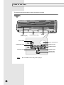
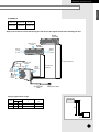
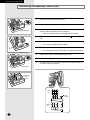
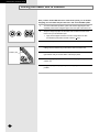
Indoor Unit
Outdoor Unit
AD18B1C09
AD26B1C13
UD18B1C2
UD26B1C2
MULTI-SPLIT TYPE ROOM AIR CONDITIONER ( Cool and Heat )
ACONDICIONADOR DE AIRE DOMÉSTICO SISTEMA MULTI SPLIT ( Refrigeración y Calefacción )
CLIMATISEUR DE TYPE MULTIPLE ( Refroidissement et Chauffage )
E S F DB98-05641A(2)
ENGLISH
ESPAÑOL
FRANÇAIS
OWNER’S INSTRUCTIONS &
INSTALLATION MANUAL
MANUAL DE INSTRUCCIONES &
MANUAL DE INSTALACIÓN
MANUEL D’UTILISATION &
MANUEL D’INSTALLATION
Safety Precautions
The following safety precautions must be taken when using your air conditioner.
1
Make sure that the indoor unit is correctly ventilated at all times; do NOT place clothing or other materials
over it.
2
NEVER spill liquid of any kind into the indoor unit. Should this happen, switch off the breaker used for your
air conditioner and contact your installation specialist.
3
Do NOT insert anything between the air flow blades, as the inner fan may become damaged and you may be
hurt. Keep children away from the indoor unit.
4
Do NOT place any obstacles in front of the outdoor unit.
5
If the remote control will not be used for a long time, remove the batteries.
6
Users of this product are cautioned not to attempt repair of this product at their own discretion.
Instead, they are requested to directly contact a designated service center or the outlet at which the
product was purchased.
7
If the supply cord is damaged, it must be replaced by a special cord or assembly available from the
manufacturer or its service centre.
8
This device must be installed according to the national electrical rules.
9
Before disposing of the remote control it is necessary to remove batteries.
10 The appliance is not intended for use by young children or infirm person without supervision;
young children should be supervised to ensure that they do not play with the appliance.
11 Max current is measured according to IEC standard for safety and current is measured according to
ISO standard for energy efficiency.
12 When the outdoor temperature is below 40°F(4°C), turn the main power off.
CAUTION
The manufacturer does not take any responsibility for any accidents that
occur because the air conditioner is not fixed firmly or installed securely,
during installing or using the product. In case you experience difficulty in
installation, you must use an installation specialist. An accident will occur
if the installation is not done as recommends in the installation guide.
E-2
ENGLISH
Contents
◆ PREPARING YOUR AIR CONDITIONER
■ Safety Precautions . . . . . . . . . . . . . . . . . . . . . . . . . . . . . . . . . .
■ View of the Unit . . . . . . . . . . . . . . . . . . . . . . . . . . . . . . . . . . . . .
■ Remote Control-Buttons and Display . . . . . . . . . . . . . . . . . . . .
■ Getting Started . . . . . . . . . . . . . . . . . . . . . . . . . . . . . . . . . . . . .
■ Inserting the Remote Control Batteries . . . . . . . . . . . . . . . . . . .
■ Installing the Remote Controller Holder . . . . . . . . . . . . . . . . . .
2
4
6
7
8
8
◆ OPERATING YOUR AIR CONDITIONER
■ 5 Way Function . . . . . . . . . . . . . . . . . . . . . . . . . . . . . . . . . . . .
■ Selecting the Automatic Operating Mode . . . . . . . . . . . . . . . .
■ Cooling Your Room . . . . . . . . . . . . . . . . . . . . . . . . . . . . . . . . .
■ Heating Your Room . . . . . . . . . . . . . . . . . . . . . . . . . . . . . . . . .
■ Changing the Room Temperature Quickly . . . . . . . . . . . . . . .
■ Removing Excess Humidity . . . . . . . . . . . . . . . . . . . . . . . . . .
■ Airing Your Room . . . . . . . . . . . . . . . . . . . . . . . . . . . . . . . . . .
■ Adjusting the Air Flow Direction Vertically . . . . . . . . . . . . . . .
■ Adjusting the Air Flow Direction Horizontally . . . . . . . . . . . . .
9
10
11
12
13
14
15
16
17
◆ PROGRAMMING YOUR AIR CONDITIONER
■ Setting the On Timer . . . . . . . . . . . . . . . . . . . . . . . . . . . . . . . . 18
■ Setting the Off Timer . . . . . . . . . . . . . . . . . . . . . . . . . . . . . . . . 19
■ Setting the Sleep Timer . . . . . . . . . . . . . . . . . . . . . . . . . . . . . . 20
◆ RECOMMENDATIONS FOR USE
■ Operating Recommendations . . . . . . . . . . . . . . . . . . . . . . . . .
■ Temperature and Humidity Ranges . . . . . . . . . . . . . . . . . . . .
■ Cleaning Your Air Conditioner . . . . . . . . . . . . . . . . . . . . . . . . .
■ Solving Common Problems . . . . . . . . . . . . . . . . . . . . . . . . . .
■ Installing a Filter (Option) . . . . . . . . . . . . . . . . . . . . . . . . . . . .
21
22
23
24
25
◆ TECHNICAL SPECIFICATIONS
E-3
View of the Unit
The design and shape are subject to change according to the model.
Indoor Unit
Air filter
(under the grille)
Air flow blades (outlet)
Air Inlet
Timer indicator
Remote Control Sensor
STANDARD indicator
SAVING indicator
SILENCE indicator
NATURE indicator
POWER indicator
On/Off & 5 Way
selection button
Note
E-4
◆ For details on the 5 Way, refer to page 9.
ENGLISH
Outdoor Unit
UD18B1C2
Air Inlet(Rear)
Air Outlet
Connection Valve
Outdoor Unit
UD26B1C2
Air Inlet(Rear)
Air Outlet
Connection Valve
E-5
Remote Control - Buttons and Display
Remote control
transmission indicator
Operating mode
(
AUTO,
COOL,
DRY,
FAN,
HEAT)
Temperature setting
Turbo mode
Sleep mode
Fan speed
Mode selection button
(AUTO, COOL, DRY, FAN, HEAT)
Temperature adjustment
buttons
Turbo/Sleep mode
selection button
Air flow direction
Fan speed adjustment
button
Swing button
On Timer setting
On Timer button
Off Timer setting
Off Timer button
Battery discharge indicator
5 Way selection button
E-6
On/Off &
Timer Set/Cancel button
ENGLISH
Getting Started
You have just purchased a split type air conditioner and it has been
installed by your installation specialist.
Your Owner’s Instructions contains valuable information on using your
air conditioner. Please take the time to read it as it will help you take full
advantage of the unit’s features.
The booklet is organized as follows.
◆ The following figures are shown on pages from 4 to 6 :
- Indoor and outdoor units
- Remote control(buttons and display)
They will help you find the buttons and understand the symbols displayed.
◆ In the main part of the installation book, you will find a series of
step-by-step procedures for each function available.
The illustrations in the step-by-step procedures use three different symbols:
PRESS
PUSH
HOLD DOWN
E-7
Inserting the Remote Control Batteries
You must insert or replace the remote control batteries when :
◆ You purchase the air conditioner
◆ The remote control does not work correctly
Note
◆
◆
◆
◆
Use two AAA, LR03 1.5V batteries.
Do not use old batteries or different kinds of batteries together.
Batteries may be completely discharged after 12 months, even
if they have not actually been used.
1
Push the battery cover on the rear of the remote control with your thumb
in the direction of the arrow and remove it.
2
Insert the two batteries, taking care to respect the polarities :
◆ + on the battery with + on the remote control.
◆ - on the battery with - on the remote control.
3
Close the cover by sliding it back until it clicks into place.
Installing the Remote Controller Holder
E-8
1
Place the remote controller holder on the wall.
2
Fix the remote controller holder by tightening the screws.
3
Put the remote controller into the holder as shown in the figure.
◆ If you want to install the holder easily, you had better install the holder
on the wooden frame.
ENGLISH
5 Way Function
You can select the 5 Way function with operating mode of the air conditioner for
more comfortable circumstances. You can use the 5 Way function with the indoor
unit as well as the remote control. Thus, you can use this function
even though you have lost your remote control.
Using with the indoor unit
1
Press the
mode.
(ON/OFF) button one time and then select the desired
To obtain a(n)...
Then select...
Normal operating
(STANDARD) mode
Reducing the uncomfortable
temperature gradually
(NATURE) mode
High fan speed
2
(POWER) mode
Compressor run time reduced
(SAVING) mode
Fan speed reduces as the temperature
decreases
(SILENCE) mode
To stop the operating, press the
turn off.
Note
(ON/OFF) button until all indicators
Even if the air conditioner has been turned on via the ON/OFF
button on the unit, operations can still be controlled using the
remote control as usual.
Selecting with the Remote Control
To select the 5 Way function with the remote control, press the 5 Way
button one or more times until the desired mode is selected.
◆ Each time you press the 5 Way button:
Each 5 Way indicator on the indoor unit lights up in order.
E-9
Selecting the Automatic Operating Mode
You can start the air conditioner in Automatic mode from your remote
control. In the Automatic mode, the standard temperature and the
optimum fan speed is selected automatically. You can adjust the
standard temperature but not the fan speed.
1
If necessary, press the
Result:
IMPORTANT
(On/Off) button.
◆ The 5 Way indicator on the indoor unit lights up.
◆ The air conditioner starts up in the mode selected
when the unit was last used.
◆ The indoor unit beeps.
The air conditioner is fitted with a protection mechanism to
prevent the unit from being damaged when it is started
immediately after being:
◆ Plugged in
◆ Stopped
lt will start up normally after three minutes.
2 If the
is not displayed at the top of the remote control,
press the MODE button on the remote control one or more times until it
appears.
3
Result:
◆ The indoor unit beeps each time you press the MODE button.
◆ The air conditioner runs in AUTO mode.
Note
You can change modes at any time.
To adjust the standard temperature (The air conditioner automatically
set the standard temperature by the current room temperature.),
press the TEMPERATURE buttons one or more times.
SET TEMP. SET TEMP.
-4°F/-2°C
SET TEMP. SET TEMP.
-2°F/-1°C Standard temperature +2°F/+1°C
< When you feel hot >
E-10
-
+4°F/+2°C
< When you feel chilly >
ENGLISH
Cooling Your Room
You must select the Cool mode if you wish to adjust the:
◆ Cooling temperature
◆ Fan speed when cooling
1
If necessary, press the
Result:
IMPORTANT
(On/Off) button.
◆ The 5 Way indicator on the indoor unit lights up.
◆ The air conditioner starts up in the mode selected
when the unit was last used.
◆ The indoor unit beeps.
The air conditioner is fitted with a protection mechanism to
prevent the unit from being damaged when it is started
immediately after being:
◆ Plugged in
◆ Stopped
lt will start up normally after three minutes.
2 If the
is not displayed at the top of the remote control,
press the MODE button on the remote control one or more times until it
appears.
3
Result:
◆ The indoor unit beeps each time you press the MODE button.
◆ The air conditioner runs in COOL mode.
Note
You can change modes at any time.
To adjust the temperature, press the TEMPERATURE buttons one or
more times until the required temperature is displayed.
Possible temperatures are between 65°F(18°C) and 86°F(30°C)
inclusive.
Result:
4
◆ Each time you press the TEMPERATURE buttons:
- The temperature is adjusted by 1°F(1°C)
- The indoor unit beeps
◆ The air conditioner starts cooling, provided that the room
temperature is higher than the selected temperature;
the fan will, however, operate.
Select the fan speed by pressing the FAN button one or more times
until the required setting is displayed:
Automatic (rotated :
)
Low
Medium
High
Result:
5
Each time you press the FAN button, the indoor unit beeps.
To control the direction of the air flow, refer to pages 16 and 17.
E-11
Heating Your Room
You must select the Heat mode if you wish to adjust the:
◆ Heating temperature
◆ Fan speed when heating
1
If necessary, press the
Result:
IMPORTANT
2
(On/Off) button.
◆ The 5 Way indicator on the indoor unit lights up.
◆ The air conditioner starts up in the mode selected when
the unit was last used.
◆ The indoor unit beeps.
The air conditioner is fitted with a protection mechanism
to prevent the unit from being damaged when it is started
immediately after being:
◆ Plugged in
◆ Stopped
It will start up normally after three minutes.
If the
is not displayed at the top of the remote control, press the
MODE button on the remote control one or more times until it appears.
◆ The indoor unit beeps each time you press the MODE button.
◆ The air conditioner runs in HEAT mode.
N o t e You can change modes at any time.
Result:
3
To adjust the temperature, press the TEMPERATURE buttons one or
more times until the required temperature is displayed.
Possible temperatures are between 61°F(16°C) and 86°F(30°C)
inclusive.
Result:
4
◆ Each time you press the TEMPERATURE buttons:
- The temperature is adjusted by 1°F(1°C)
- The indoor unit beeps
◆ The air conditioner starts heating, provided that the room
temperature is lower than the desired temperature
(selected temperature +6°F/+3°C); the fan will, however,
operate.
Select the fan speed by pressing the FAN button one or more times
until the required setting is displayed:
Automatic (rotated :
)
Low
Medium
High
Result:
5
E-12
◆ Each time you press the FAN button, the indoor unit beeps.
◆ For the first three to five minutes, the fan operates very
slowly until the air has been sufficiently warmed. Once the
correct temperature has been reached, the fan is automatically
set to the required speed.
To control the direction of the air flow, refer to pages 16 and 17.
ENGLISH
Changing the Room Temperature Quickly
The Turbo cooling/heating function is used to cool or heat your room as
quickly as possible.
Example :
You have just come home and find that the room is very
hot. You wish to cool it down as quickly as possible.
The Turbo function operates for 30 minutes with the maximum settings before
returning automatically to the mode and temperature previously selected.
1
If necessary, press the
Result:
2
Press the
Result:
3
button.
◆ The temperature and fan settings are adjusted automatically.
◆ The air conditioner cools or heats the room as quickly as possible.
◆ After 30 minutes, the air conditioner is reset automatically to the
previous mode, temperature and fan settings.
But, if you press the
button in DRY or FAN mode,
it will change to AUTO mode automatically.
If you wish to stop the Turbo function before the end of the 30-minute period,
press the
button one or more times until
or
disappears.
Result:
4
(On/Off) button.
◆ The 5 Way indicator on the indoor unit lights up.
◆ The air conditioner starts up in the mode selected when the unit
was last used.
◆ The indoor unit beeps.
The air conditioner is reset automatically to the previous mode,
temperature and fan settings.
To control the direction of the air flow, refer to pages 16 and 17.
E-13
Removing Excess Humidity
If the atmosphere in your room is very humid or damp, you can
remove excess humidity without lowering the room temperature too
much.
1
If necessary, press the
Result:
◆ The 5 Way indicator on the indoor unit lights up.
◆ The air conditioner starts up in the mode selected when
the unit was last used.
◆ The indoor unit beeps.
IMPORTANT
2
(On/Off) button.
The air conditioner is fitted with a protection mechanism
to prevent the unit from being damaged when it is started
immediately after being:
◆ Plugged in
◆ Stopped
It will start up normally after three minutes.
If the
is not displayed at the top of the remote control, press the
MODE button on the remote control one or more times until it appears.
◆ The indoor unit beeps each time you press the MODE button.
◆ The air conditioner runs in DRY mode.
N o t e You can change modes at any time.
Result:
3
To adjust the temperature, press the TEMPERATURE buttons one or
more times until the required temperature is displayed.
Possible temperatures are between 65°F(18°C) and 86°F(30°C)
inclusive.
Result:
4
E-14
◆ Each time you press the TEMPERATURE buttons:
- The temperature is adjusted by 1°F(1°C)
- The indoor unit beeps
◆ The air conditioner starts removing the excess humidity;
the quantity of air is adjusted automatically.
To control the direction of the air flow, refer to pages 16 and 17.
ENGLISH
Airing Your Room
If the atmosphere in your room is stale, you can air the room using
the Fan feature.
1
If necessary, press the
Result:
2
If the
is not displayed at the top of the remote control,
press the MODE button on the remote control one or more times until it
appears.
Result:
Note
3
(On/Off) button.
◆ The 5 Way indicator on the indoor unit lights up.
◆ The air conditioner starts up in the mode selected when
the unit was last used.
◆ The indoor unit beeps.
◆ The indoor unit beeps each time you press the MODE button.
◆ The air conditioner runs in FAN mode.
◆ The temperature is set automatically.
You can change modes at any time.
Select the fan speed by pressing the FAN button one or more times
until the required setting is displayed:
Low
Medium
High
Result:
4
Each time you press the FAN button, the indoor unit beeps.
To control the direction of the air flow, refer to pages 16 and 17.
E-15
Adjusting the Air Flow Direction Vertically
Depending on the position of the indoor unit on the wall of your room,
you can adjust the position of the outer air flow blade on the bottom of
the unit, thus increasing the efficiency of the air conditioner.
1
Press the SWING button one or more times as required.
Result: The outer blade is adjusted vertically.
RECOMMENDATION
2
Upwards.
Downwards.
The blade move up and down, around the base position set.
To stop the blade moving up and down, press the SWING button again.
Note
E-16
Adjust the blade to face...
Cooling
Heating
If you want the blade to move up and down automatically when the air
conditioner is operating, press the SWING button.
Result:
3
When...
If you switch the air conditioner... Then the blade is...
Off
Closed completely.
On again
Set to the initial position powered.
ENGLISH
Adjusting the Air Flow Direction Horizontally
There are two sets of inner air flow blades. Just as the outer air flow
blade can be adjusted vertically, the inner blades can be adjusted
horizontally.
1
Adjust each set of inner blades to the required position, by pushing or
pulling them sideways.
E-17
Setting the On Timer
The On Timer enables you to switch on the air conditioner automatically
after a given period of time. You can set the period of time from
30 minutes to 24 hours.
1
To set the operating time, press the ON TIMER button one or more times
until the required time is displayed. Possible time is between 0.5 hour and
24 hour inclusive.
2
Press the
Result:
3
(Set/Cancel) button to complete the setting.
◆ The remaining time is displayed.
◆ Blinking of the timer indicator stops.
◆ The selected mode and the temperature on the display
disappear after 10 seconds.
◆ The air conditioner will switch on automatically when the
counter displayed on the remote control reaches the set time
and disappears the On timer setting.
To select an operating mode in advance, press the
button until the
desired mode is displayed at the top of the remote control.
Result:
◆ The air conditioner will run in the selected mode when it is
turned on.
To Cancel the On Timer
1
To cancel the On Timer, press the ON TIMER button one or more times
until the timer setting disappears.
2
Press the
Note
E-18
(Set/Cancel) button.
If you want to turn on the air conditioner before the timer reaches
the setting time, press the (ON/OFF) button.
ENGLISH
Setting the Off Timer
The Off Timer enables you to switch off the air conditioner automatically
after a given period of time. You can set the period of time from
30 minutes to 24 hours.
1
To set the operating time, press the OFF TIMER button one or more times
until the required time is displayed. Possible time is between 0.5 hour and
24 hour inclusive.
2
Press the
Result:
(Set/Cancel) button to complete the setting.
◆ The remaining time is displayed.
◆ Blinking of the timer indicator stops.
◆ The air conditioner will switch off automatically when the
counter displayed on the remote control reaches the set time
and disappears the Off timer setting.
Example If you would like to turn the air conditioner on after 2 hours
and to operate it for 2 hours:
1. Press the ON TIMER button until ‘2.0 Hr’ is displayed.
2. Press the (Set/Cancel) button.
3. Press the OFF TIMER button until ‘4.0 Hr’ is displayed.
4. Press the (Set/Cancel) button.
Note
You can see or change the setting mode and/or the temperature
by pressing the MODE button or the TEMPERATURE buttons
after setting the Off timer.
To Cancel the Off Timer
1
To cancel the Off Timer, press the OFF TIMER button one or more times
until the timer setting disappears.
2
Press the
Note
(Set/Cancel) button.
If you want to turn off the air conditioner before the timer reaches
the setting time, press the
(ON/OFF) button.
E-19
Setting the Sleep Timer
The Sleep Timer can be used when you are cooling or heating your
room to switch the air conditioner off automatically after a period of
six hours.
Note
If you wish to switch the unit off at a specific time, refer to
page 19.
1
Make sure that you have selected either COOL or HEAT mode.
2
Press the
button one or more times until
remote control.
appears on the
◆ The indoor unit beeps.
◆ The air conditioner will be controlled as indicated in the
illustrations below.
Result:
Cooling
The desired temperature is
increased by 2°F/1°C every
hour.
When it has been increased
by 4°F/2°C (after two hours),
the temperature is maintained
for four hours.
Heating
The desired temperature is
decreased by 2°F/1°C every
hour.
When it has been decreased
by 4°F/2°C (after two hours),
the temperature is maintained
for four hours.
To Cancel the Sleep Timer
If you no longer wish to use the Sleep Timer that you have set, you
can cancel it at any time.
Press the
Result:
E-20
button.
◆
◆
◆
The indoor unit beeps.
The
is no longer displayed.
The air conditioner operates normally.
ENGLISH
Operating Recommendations
Here are a few recommendations that you should follow when using
your air conditioner.
Topic
Recommendation
Heating performances
The heat pump inside the air conditioner
absorbs heat from outside air and brings it
indoors. If the temperature of the outside air
drops, the air conditioner will heat less. If you
find that the room is not warm enough, use an
additional heating appliance.
Warm air circulation
The air conditioner circulates warm air to heat
your room; as a result, some time will be
required after starting the air conditioner to
warm the entire room. If necessary, set the air
conditioner on before you wish to use the
room.
Frost
When outside temperatures are low and
humidity is high, frost may form in the outdoor
unit when heating is selected.
If this happens:
◆ The heating operation is stopped.
◆ The Deice mode is triggered automatically
for about seven minutes.
No intervention is required from you; after
about seven minutes, the air conditioner starts
operating again normally.
High indoor and outdoor
temperatures
If both the indoor and outdoor temperatures
are high and you select the Heat mode, the
outdoor unit’s fan and compressor may stop at
times. This is normal; simply wait until the air
conditioner switches on again.
Power failure
If a power failure occurs when the air
conditioner is operating, the unit is switched off.
When the power returns, you must press the
(ON/OFF) button to restart it.
E-21
Temperature and Humidity Ranges
The following table indicates the temperature and humidity ranges
within which the air conditioner can be used.
If the air conditioner is used at...
Then...
High temperatures
The automatic protection feature may
be triggered and the air conditioner
stopped.
Low temperatures
A water leak or some other malfunction
may occur if the heat exchanger
freezes.
High humidity levels
Water may condense on and drip
from the surface of the indoor unit if it
is used for long periods.
Mode
Outdoor Temperature
Indoor Temperature
Heating
32°F to 75°F approx.
0°C to 24°C approx.
81°F or less
27°C or less
70°F to 109°F approx.
21°C to 43°C approx.
65°F to 90°F approx.
18°C to 32°C approx.
65°F to 109°F approx.
18°C to 43°C approx.
65°F to 90°F approx.
18°C to 32°C approx.
Cooling
Drying
❇
Indoor Humidity
-
80% or less
-
If the heating operation is used at below 32°F/0°C(outdoor temperature)
then, it does not heat as its full capacity.
If the cooling operation is used at over 92°F/33°C(indoor temperature)
then, it does not cool as its full capacity.
E-22
ENGLISH
Cleaning Your Air Conditioner
To get the best possible use out of your air conditioner, you must
clean it regularly to remove the dust that accumulates on the air filter.
IMPORTANT
Before cleaning your air conditioner, ensure that you
have switched off the breaker used for the unit.
1
Open the front grille by lifting the tabs on the lower right and left sides of
the indoor unit.
2
Disassemble the front grille by pulling it forwards.
3
Hold the edge of the air filter under the front grille and pull to release them.
4
Remove all dust on the air filters with a vacuum cleaner or brush.
5
Clean the front panel with a damp cloth and mild detergent
(do NOT use benzene, solvents or other chemicals).
6
Reassemble the air filters and the front grille.
Note
◆ If you have not used the air conditioner for a long period
of time, set the fan going for three to four hours to dry
the inside of the air conditioner thoroughly.
E-23
Solving Common Problems
Before contacting the after-sales service, perform the following simple checks.
They may save you the time and expense of an unnecessary call.
Problem
E-24
Explanation/Solution
The air conditioner does not
operate at all
◆ Check that the breaker used for the air conditioner is switched on.
◆ Check that the 5 Way indicator on the indoor unit is on;
if necessary press the
(On/Off) button on the remote control.
◆ Check whether the TIMER indicator on the indoor unit is switched on.
If so:
- Wait until the switch-on time is reached and the air conditioner starts
up automatically
- Cancel the timer (see pages 18 and 19 for further details)
The air conditioner does not
operate with the remote control
◆ Check that there are no obstacles between you and the indoor unit.
◆ Check the remote control batteries.
◆ Check that you are close enough to the indoor unit
(seven metres/yards/23ft. or less).
No beep is heard when you press
the
(On/Off) on the remote
control
◆ Check that you are pointing the remote control at the remote control
sensor in the right of the indoor unit.
◆ Replace the remote control batteries if necessary.
The air conditioner does not cool
or heat
◆ Check that the correct operating mode has been selected
(AUTO, COOL, HEAT).
◆ The room temperature may be too low or too high.
◆ Dust may be blocking the air filter guard; refer to page 23 for cleaning
instructions.
◆ Check that there is no obstacle in front of the outdoor unit.
When heating, the required room
temperature is never reached and
the air conditioner frequently stops
◆ Check that the required temperature has been set correctly.
◆ Increase the fan speed.
◆ If the air flow is directed downwards, use the remote control to direct it
upwards.
The fan speed does not change
when you press the FAN button
◆ Check that the operating mode is set to COOL, HEAT or FAN ;
in the AUTO mode, the fan speed changes automatically and in the
DRY mode, it is set to AUTO.
The air flow direction does not
change when you press the
SWING button
◆ Check that the air conditioner has been switched on; if necessary,
press the
(On/Off) button on the remote control.
The timer is not correctly triggered
◆ Check that the timer has been programmed correctly; see pages 18
and 19.
Odours are permeated in the room
during air conditioning
◆ Air the room.
ENGLISH
Installing a Filter (Option)
The air conditioner can be fitted with a deodorizing and Bio-Pure
filter to remove minute dust particles or odours. The service life of
the filter is approximately three months depending on the time
during which the air conditioner is used.
1
Remove the vinyl packing from the filter.
Note
2
Do not remove the packing from a deodorizing filter until you
wish to use the filter, as it will lose its properties.
Insert the filter in the filter holder and press the three insert tabs until
you hear a click.
3
Open the front grille by pulling on the tabs on the lower right and left
sides of the indoor unit.
4
Take out the existing filter and replace it with the new one.
Deodorizing
filter
Bio-Pure Filter
E-25
Technical Specifications
MODEL
Indoor unit
Outdoor unit
Indoor unit
Outdoor unit
AD18B1C09
UD18B1C2
AD26B1C13
UD26B1C2
TYPE
2 Comp + 2 Room
2 Comp + 2 Room
Btu/h
A/B-Unit : 9000
A/B-Unit : 12500
Btu/h
A/B-Unit : 9500
A/B-Unit : 13500
HSPF
6.8
6.8
SEER
10.0
10.0
Performance Capacity Cooling
Ratings
Capacity Heating
Moisture Removal
Pts/h
3
-
4
-
Air FLOW(Cooling, HIGH)
CFM
255
-
300
-
Air FLOW(Heating, HIGH)
CFM
265
-
310
-
dB
-
57
-
62
Sound Rating-Outdoor
Electrical
Data
1 Unit operation 2 Unit operation 1 Unit operation 2 Unit operation
The number of operation
208-230V~,60Hz
Power source
Min.Ampacity(C/H)
A
4.3/4.0
8.4/7.8
6.1/6.2
11.4/11.6
Cooling Watts
W
990
1920
1360
2550
Heating Watts
W
920
1780
1370
2600
A-Unit
B-Unit
A-Unit
B-Unit
Refrigeration Indoor unit
Lines
Connections
Flare
Flare
Liquid Line O. D.
mm(in)
6.35(1/4)
6.35(1/4)
Suction Line O.D.
mm(in)
9.52(3/8)
12.70(1/2)
Factory Pre-charge
m(ft)
5.0 ( 16 12 )
5.0 ( 16 12 )
Max. Line length
m(ft)
15.0 ( 49 14 )
15.0 ( 49 1 )
Max. Height Difference
m(ft)
7.0 (23)
7.0 (23)
Dimensions W X H X D
& Weight
mm(in)
✳ Standard rating conditions
4
790 x 245 x 165 880 x 638 x 310 790 x 245 x 165 1000 x 790 x 310
( 31 81 x 9 12 x 6 21 ) ( 34 21 x 25 81 x 12 14 ) ( 31 18 x 9 12 x 6 21 ) ( 39 21 x 3181 x 12 41 )
17
Ibs
Net Weight
Cooling
132.3
17
Outdoor
Indoor
WB
DB
DB
WB
°F
80
67
95
75
°C
26.7
19.4
35.0
23.9
Heating
Outdoor
Indoor
DB
E-26
208-230V~,60Hz
WB
DB
WB
°F
70
60
47
43
°C
21.1
15.6
8.3
6.1
152.1
ENGLISH
Memo
E-27
INSTALLATION
MANUAL
E-28
ENGLISH
Contents
◆ PREPARING THE INSTALLATION
■ Deciding on Where to Install the Air Conditioner . . . . . . . . . . . 30
■ Air Conditioner and Accessories . . . . . . . . . . . . . . . . . . . . . . . 33
◆ INSTALLING THE INDOOR UNIT
■ Fixing the Installation Plate . . . . . . . . . . . . . . . . . . . . . . . . . . .
■ Purging the Unit . . . . . . . . . . . . . . . . . . . . . . . . . . . . . . . . . . .
■ Connecting the Assembly Cable . . . . . . . . . . . . . . . . . . . . . . .
■ Installing and Connecting the Indoor Unit Drain Hose . . . . . .
■ Installing and Connecting the Indoor Unit Assembly Piping . .
■ Cutting/Extending the Piping . . . . . . . . . . . . . . . . . . . . . . . . . .
34
35
35
37
38
39
◆ INSTALLING THE OUTDOOR UNIT
■ Connecting the Cables to the Outdoor Unit . . . . . . . . . . . . . .
■ Auxillary Circuit Breaker . . . . . . . . . . . . . . . . . . . . . . . . . . . . .
■ Electrical Work . . . . . . . . . . . . . . . . . . . . . . . . . . . . . . . . . . . .
■ Checking Correct Earthing . . . . . . . . . . . . . . . . . . . . . . . . . . .
■ Installing and Connecting the Outdoor Unit Drain Hose . . . . .
■ Fixing the Unit in Position . . . . . . . . . . . . . . . . . . . . . . . . . . . .
40
41
41
42
43
43
◆ COMPLETING THE INSTALLATION
■ Connecting Up and Purging the Circuit . . . . . . . . . . . . . . . . . .
■ Performing Leak Tests . . . . . . . . . . . . . . . . . . . . . . . . . . . . . .
■ Placing the Indoor Unit in Position . . . . . . . . . . . . . . . . . . . . .
■ Checking and Testing Operations . . . . . . . . . . . . . . . . . . . . . .
■ Explaining Operations to the Owner . . . . . . . . . . . . . . . . . . . .
44
45
46
47
52
E-29
PREPARING THE INSTALLATION
Deciding on Where to Install the Air Conditioner
When deciding on the location of the air conditioner with the owner, the following restrictions
must be taken into account.
General
Do NOT install the air conditioner in a location where it will come into contact with the following elements:
◆ Combustible gases
◆ Saline air
◆ Machine oil
◆ Sulphide gas
◆ Special environmental conditions
If you must install the unit in such conditions, first consult your dealer.
Indoor Unit
◆ There must be no obstacles near the air inlet and outlet.
◆ Install the indoor unit on a surface that can support its weight.
◆ Choose a position that enables the piping and cables to be easily connected to the outdoor unit and the
recommended length of 5m (16ft. 5in) to be respected (15m (49ft.3in) maximum).
◆ Leave enough clearance beneath the indoor unit to enable the filters to be removed without hindrance.
◆ Maintain sufficient clearance around the indoor unit, as indicated in the diagram on the page opposite.
◆ Make sure that the water dripping from the drain hose runs away correctly and safely.
Outdoor Unit
◆ The outdoor unit must NEVER be placed on its side or upside down, as the compressor lubrication oil will run into the
cooling circuit and seriously damage the unit.
◆ Choose a location that is dry and sunny, but not exposed to direct sunlight or strong winds.
◆ Do not block any passageways or thoroughfares.
◆ Choose a location where the noise of the air conditioner when running and the discharged air do not disturb any
neighbours.
◆ Choose a position that enables the piping and cables to be easily connected to the indoor unit and the recommended
length of 5m (16ft. 5in) to be respected (15m (49ft.3in) maximum).
◆ Install the outdoor unit on a flat, stable surface that can support its weight and does not generate any unnecessary
noise and vibration.
◆ Position the outdoor unit so that the air flow is directed towards the outside, as indicated by the arrows on the top of
the unit.
◆ Maintain sufficient clearance around the outdoor unit, as indicated in the diagram on the page opposite.
◆ If the outdoor unit is installed at a height, ensure that its base is firmly fixed in position; the maximum height is
7m (23ft).
◆ Make sure that the water dripping from the drain hose runs away correctly and safely.
CAUTION
◆ You have just purchased a split-type room air conditioner and it has been
installed by your installation specialist.
◆ This device must be installed according to the national electrical rules.
◆ When the outdoor temperature is below 40°F(4°C), turn the main power off.
E-30
ENGLISH
PREPARING THE INSTALLATION
◗ 18,000Btu/h
Indoor unit
Outdoor unit
Power supply
Ø, V, Hz
AD18B1C09
UD18B1C2
1,208-230~,60
Respect the clearances and maximum lengths indicated in the diagram below when installing the unit.
B-unit
9,000 Btu/h
25 mm (1 inch)
or more
A-unit
9,000 Btu/h
160 mm
(6 inch)
or more
100 mm
(4 inch)
or more
B
(7 m (23ft) maximum)
600 mm (24 inch)
minimum
100 mm
(4 inch)
minimum
100 mm
(4 inch)
minimum
600 mm
(24 inch)
minimum
A
(15 m (49ft. 3in)
maximum)
A
B
Circuit breaker
(20A)
Main power switch
Piping length and the height.
INDOOR UNIT
Pipe size
Liquid GAS
A-unit 1/4" 3/8"
B-unit 1/4" 3/8"
Unit
MAX. piping length
A
15 m (49ft. 3in)
15 m (49ft. 3in)
MAX. height
B
7 m (23ft)
7 m (23ft)
A
B
OUTDOOR UNIT
E-31
PREPARING THE INSTALLATION
Deciding on Where to Install the Air Conditioner (cont.)
◗ 26,000Btu/h
Indoor unit
Outdoor unit
Power supply
Ø, V, Hz
AD26B1C13
UD26B1C2
1,208-230~,60
Respect the clearances and maximum lengths indicated in the diagram below when installing the unit.
B-unit
12,500 Btu/h
25 mm (1 inch)
or more
A-unit
12,500 Btu/h
100 mm
(4 inch)
or more
160 mm
(6 inch)
or more
B
(7 m (23ft) maximum)
600 mm (24 inch)
minimum
A
(15 m (49ft. 3in)
maximum)
100 mm
(4 inch)
minimum
100 mm
(4 inch)
minimum
600 mm
(24 inch)
minimum
A
B
Circuit breaker
(20A)
Piping length and the height.
INDOOR UNIT
A
B
OUTDOOR UNIT
E-32
Main power switch
Pipe size
Liquid GAS
A-unit 1/4" 1/2"
B-unit 1/4" 1/2"
Unit
MAX. piping length
A
15 m (49ft. 3in)
15 m (49ft. 3in)
MAX. height
B
7 m (23ft)
7 m (23ft)
PREPARING THE INSTALLATION
ENGLISH
Air Conditioner and Accessories
The following accessories are supplied with the air conditioner.
➢
The quantities are indicated in parentheses.
Accessories in the Indoor Unit Case
Installation Plate (1)
Remote Control (1)
Batteries for
Remote Control (2)
Owner’s Instruction
Booklet & Installation
Manual (1)
NS
NES
OWNER’S INSTRUCTIO
INSTRUCCIO
MANUAL DE
PER L’USO
ISTRUZIONIINSTRU
˝ES
MANUAL DE
ION
MANUEL D’UTILISAT G
GEBRAUCHSANWEISUN
Air Conditioner
Splut-type Room stico sistema Split
dom
ad unit Separate
Aire acondicionado
d’aria per ambienti
Condizionatorede ar condicionado tipo Split
Aparelho
type s par
Climatiseur de
Geteilte raumklimaanlage
Remote controller
holder (1)
Screws (2)
Accessories in the Outdoor Unit Case
Drain Plug
➢
Rubber Leg
Flare Nuts,6.35mm(1/4˝)
outer pipe diameter
Flare Nuts,9.52mm(3/8˝)
outer pipe diameter
Flare Nuts, 12.70mm(1/2˝)
outer pipe diameter
The assembly cable is depending on the option. [If they are not supplied, Using the
standard cable.(approved according to IEC standard.)]
E-33
PREPARING THE INSTALLATION
Fixing the Installation Plate
Before fixing the installation plate to a wall or window frame, you
9
must determine the position of the 65mm( 2 16 inch) hole through
which the cable, piping and hose pass to connect the indoor unit up
to the outdoor unit. When facing the air conditioner in position on
the wall, the piping and cable can be connected from the:
◆ Right
◆ Left
◆ Rear (right or left)
1
Determine the position of the pipe and drain hose hole using the right
figure and drill the hole with an inner diameter of 65mm( 2 169 inch) so that it
slants slightly downwards.
2
If you are fixing the indoor unit to a...
Then follow Steps...
Wall
3.
Window frame
4 to 6.
3
30mm(116
)
Unit : mm(inch) Installation plate
Pipe Hole
9
)
0 65mm (2 16
3
Fix the installation plate to the wall in a manner appropriate to the weight
of the indoor unit.
60 (2
Unit : mm(inch)
3
8)
➢ If you are mounting the plate on a concrete wall with anchor bolts, the
anchor bolts must not project by more than 20mm( 34 inch).
252 (10)
4
Determine the positions of the wooden uprights to be attached to the
window frame.
5
Attach the wooden uprights to the window frame in a manner appropriate
to the weight of the indoor unit.
6
Using tapped screws, attach the installation plate to the wooden uprights,
as illustrated in the last figure opposite.
3
30 (116 )
275 (11)
90 (3
5
8
)
140 (5
1
2
)
410~730 (16
1
8
~28
3
4
)
Unit : mm(inch)
E-34
INSTALLING THE INDOOR UNIT
ENGLISH
Purging the Unit
On delivery, the indoor unit is loaded with an inert gas. All this gas
must therefore be purged before connecting the assembly piping.
To purge the inert gas, proceed as follows.
Unscrew the caps at the end of each pipe.
Result: All inert gas escapes from the indoor unit.
➢
To prevent dirt or foreign objects from getting into the pipes
during installation, do NOT remove the caps completely
until you are ready to connect the piping.
Connecting the Assembly Cable
The outdoor unit is powered from the indoor unit via the assembly cable.
If the outdoor unit is more than 5m(16ft. 5in) away from the indoor unit, the
cable must first be extended to a maximum of 15m(49ft. 3in).
1
Extend the assembly cable if necessary.
2
Open the front grille by pulling on the tabs on the lower right and left sides of
the indoor unit; if necessary, refer to page 23.
3
4
Remove the screw securing the connector cover, then open the connector
cover.
❊ The designs and shape are subject to
change according to the model.
Connector
cover
Remove three screws securing the front panel, then detach the front panel
from the indoor unit.
E-35
INSTALLING THE INDOOR UNIT
Connecting the Assembly Cable (cont.)
5
Detach the control box from the indoor unit.
6
Install the conduit kit. (The conduit kit is optional)
7
Pass the assembly cable through the rear of the indoor unit and connect the
assembly cable to terminals as shown in the figure.
Control Box
➢ Each wire is labelled with the corresponding terminal number.
A
8
Pass the other end of the cable through the 65mm( 2 169 inch) hole in the
wall.
9
Reinstall the control box, then tighten the C screw.
➢ The C screw is provided with this manual.
10
B
Install the D terminal block cover, tightening the E screws.
➢ The D terminal block cover and E screws are provided with this manual.
❊ The conduit kit is optional(A and B).
C
11
Replace the front panel, carefully tightening the screws.
12
Reinstall the front grille.
13
For further details on how to plug the other end of the assembly cable into
the outdoor unit, refer to page 40.
Control Box
E
D Terminal
block
cover
Indoor
unit
1
Outdoor 1
unit
2
3
2
3
E
A1 A2 A3
Earth terminal
E-36
E
E
Earth
terminal
INSTALLING THE INDOOR UNIT
ENGLISH
Installing and Connecting the Indoor Unit Drain Hose
Care must be taken when installing the drain hose for the indoor unit to ensure that any
condensation water is correctly drained outside. When passing the drain hose through
the 65mm( 2 169 inch) hole drilled in the wall, check that none of the following situations occur.
5cm
(2inch)
less
The hose must
NOT slope
upwards.
The end of the drain
hose must NOT be
placed in water.
Do NOT bend the
hose in different
directions.
Keep a clearance of at
least 5cm(2inch)
between the end of the
hose and the ground.
Ditch
Do NOT place the
end of the drain hose
in a hollow.
To install the drain hose, proceed as follows.
1
If necessary, connect the 2m(6ft. 7in) extension to the drain hose.
2
If you are using the extension, insulate the inside part of the extension
drain hose with a shield.
3
Pass the drain hose under the refrigerant piping, taking care to keep the
drain hose tight.
4
Pass the drain hose through the hole in the wall, making sure that it is
sloping downwards, as shown in the illustrations above.
Shield
Drain hose
➢
Extension drain hose
The hose will be fixed permanently into position once the
whole installation has been tested for gas leaks; refer to
page 46 for further details.
E-37
INSTALLING THE INDOOR UNIT
Installing and Connecting the Indoor Unit Assembly Piping
There are two refrigerant pipes of different diameters:
◆ A smaller one for the liquid refrigerant
◆ A larger one for the gas refrigerant
A short length of piping is already fitted to the air conditioner. You
must extend this piping using assembly piping (optionally supplied).
The connection procedure for the refrigerant piping varies according
to the exit position of the piping from the indoor unit, as seen when
facing the air conditioner in position on the wall:
◆ Right (A)
◆ Left (B)
◆ Rear
B
A
1
With a knife, cut out the appropriate knock-out piece on the rear of the
indoor unit (unless you are connecting directly from the rear).
2
Smooth the cut edges.
3
Remove the protection caps on the pipes and connect the assembly piping
to each pipe, tightening the nuts, first manually and then with a wrench,
applying the following torque.
Pipe
Outer Diameter
Torque
Liquid refrigerant
6.35 mm(1/4˝)
160kg•cm(11.6ft•lb )
Gas refrigerant
9.52 mm(3/8˝)
300kg•cm(21.8ft•lb )
Gas refrigerant
12.70 mm(1/2˝)
500kg•cm(36.4ft•lb )
➢ If the piping must be shortened or extended, refer to page 39.
4
Cut off any excess foam insulation.
5
If necessary, bend the pipe round, along the bottom of the indoor unit and
out through the appropriate hole, taking care to ensure that:
◆ The piping does not jut out from the rear of the indoor unit
◆ The bending radius is 100mm (4inch) or more
6
Pass the piping through the hole in the wall.
7
For further details on how to connect up to the outdoor unit and purge the
circuit, refer to page 44.
➢ The piping will be insulated and fixed permanently into
position once the whole installation has been tested for
gas leaks; refer to page 46 for further details.
E-38
INSTALLING THE INDOOR UNIT
ENGLISH
Cutting/Extending the Piping
5 metres(16ft. 5in) of piping is supplied with the air
conditioner(Optional). This length can if necessary be:
◆ Extended to a maximum of 15m(49ft. 3in)
◆ Shortened as required
☛
If more than 5m(16ft. 5in) of piping is required:
◆
The assembly cable must also be extended
◆
Refrigerant must be added to the circuit by an
approved installer; otherwise, the indoor unit may
freeze
1
Make sure that you have the required tools available
(pipe cutter, reamer, flaring tool and pipe holder).
2
If you wish to shorten the piping, cut it using a pipe cutter, taking care to
ensure that the cut edge remains at a 90° angle with the side of the pipe,
and referring to the illustrations below for examples of edges cut correctly
and incorrectly.
Oblique
Rough
Burr
90
O
O
x
x
x
3
To prevent any gas from leaking out, remove all burrs at the cut end of the
pipe, using a reamer.
4
Slide a flare nut on to the pipe and modify the flare.
Pipe
Liquid refrigerant
Gas refrigerant
Gas refrigerant
5
x
Inclined
x
Damaged Surface
x
Cracked
Uneven Thickness
Align the pipes to be connected and tighten the flare nuts first manually
and then with a wrench, applying the following torque.
Pipe
Liquid refrigerant
Gas refrigerant
Gas refrigerant
7
Depth (A)
1.3 mm(1/16˝)
1.8 mm(1/16˝)
2.0 mm(1/16˝)
Check that the flaring is correct, referring to the illustrations below for
examples of incorrect flaring.
x
6
Outer Diameter (D)
6.35 mm(1/4˝)
9.52 mm(3/8˝)
12.70 mm(1/2˝)
Outer Diameter
6.35 mm(1/4˝)
9.52 mm(3/8˝)
12.70 mm(1/2˝)
Torque
160kg•cm(11.6ft•lb )
300kg•cm(21.8ft•lb )
500kg•cm(36.4ft•lb )
For further details on how to connect up to the outdoor unit and purge the
circuit, refer to page 44.
E-39
INSTALLING THE INDOOR UNIT
Connecting the Cables to the Outdoor Unit
One electric cable must be connected to the outdoor unit:
◆ The assembly cable connecting the indoor unit to the outdoor unit
UD18B1C2
1
Remove the terminal board cover on the side of the outdoor unit.
2
Connect the assembly cable to terminals as shown in the figure.
➢
Each wire is labelled with the corresponding terminal number.
UD26B1C2
3
Connect the earth wires to the earth terminals.
➢ Refer to the page 42 for further details on how to check
that earthing is correct.
4
Replace the terminal board cover, carefully tightening the screw.
Outdoor unit
A1
A2
A3
B1
B2
B3
L1
L2
A
B
Terminal block
Earth
E terminal
Circuit Breaker
(Main Power
supply cable)
1
2
3
E
Earth
terminal
1
2
3
E
Earth
terminal
Assembly
cable
1
2
3
E
Earth
terminal
1
2
3
Indoor
unit
A-unit
E-40
B-unit
E
Earth
terminal
INSTALLING THE OUTDOOR UNIT
ENGLISH
Auxiliary Circuit Breaker
◆ Auxiliary circuit breaker should be installed near outdoor unit so
that each access is possible. Main/outdoor power supply cable are
connected to upper/lower terminal of auxiliary circuit breaker.
◆ It is necessary that the conduit kit for power supply to the outdoor
unit be installed between auxiliary power S/W and the outdoor
unit. (the conduit kit is optional)
Outdoor unit
Distribution
board
Auxiliary
power s/w
❊ The designs and shape are subject to
change according to the model.
Electrical Work
1
The supply voltage must be the same as the rated voltage of the
air conditioner.
2
Prepare the power souce for exclusive use with the air conditioner.
3
Use 20 amperes time delay fuse or circuit breaker.
MODEL
AD18B1C09
AD26B1C13
Power supply
208-230V~/60Hz
Power cable
3G AWG 14
Assembly cable
4G AWG 16
Operating current(C/H)
Starting Current
Power consumption (C/H)
8.4A / 7.8A
11.4A / 11.6A
22A
31A
1920W / 1780W
2550W / 2600W
➢ When using the special NFB, use the NFB to bear the capacity of
the air conditioner.
➢ Otherwise, the shot circuit in the NFB may occur.
E-41
INSTALLING THE OUTDOOR UNIT
Checking Correct Earthing
If the power distribution circuit does not have an earth or the earth
does not comply with specifications, an earthing electrode must be
installed. The corresponding accessories are not supplied with the air
conditioner.
Carbon
plastic
1
Select an earthing electrode that complies with the specifications given in
the illustration opposite.
2
Determine a suitable location for the earthing electrode:
◆ In damp hard soil rather than loose sandy or gravel soil that has a
higher earthing resistance
◆ Away from underground structures or facilities, such as gas pipes,
water pipes, telephone lines and underground cables
◆ At least 2m(6ft. 7in) away from a lightening conductor earthing
electrode and its cable
Steel
core
PVC-insulated green/
yellow wire, 2mm2 x 3.5 m
To
earthing
screw
Unit : cm(inch)
3
4
➢
)
The earthing wire for the telephone line cannot be used to
earth the air conditioner.
30 (11
3
4
)
50 (19
3
Dig a hole of the size indicated in the illustration opposite, drive the
earthing electrode into position and cover the top of the electrode
with the excavated soil.
4
Install a green/yellow insulated earthing wire (Ø1.6 mm/ 16 ˝, section
2 mm2 or greater):
◆ If the earthing wire is too short, connect an extension lead, soldering
the connection and wrapping it with insulating tape (do not bury the
soldered connection)
◆ Secure the earthing wire in position with staples
1
➢ If the earthing electrode is installed in an area of heavy traffic,
its wire must be connected securely.
E-42
5
Carefully check the installation, by measuring the earthing resistance with
an earthing resistance tester. If the resistance is above the required level,
drive the earthing electrode deeper into the ground or increase the number
of earthing electrodes.
6
Connect the earthing wire to the earthing screw on the air conditioner.
INSTALLING THE OUTDOOR UNIT
ENGLISH
Installing and Connecting the Outdoor Unit Drain Hose
When using the air conditioner in the heating mode, ice may
accumulate. During de-icing, the condensed water must be drained
off safely. Consequently, you must install a drain hose on the outdoor
unit, following the instructions below.
1
Insert the drain plug into the drain hole on the underside of the outdoor
unit.
2
Connect the drain hose to the drain plug.
3
Ensure that the drained water runs off correctly and safely.
Drain hole
Fixing the Unit in Position
The outdoor unit must be installed on a rigid and stable base to avoid any increase
in the noise level and vibration, particularly if the outdoor unit is to be installed close
to a neighbour. If it is to be installed in a location exposed to strong winds or at a
height, the unit must be fixed to an appropriate support (wall or ground).
2
Position the outdoor unit so that the air flow is directed towards the
outside, as indicated by the arrows on the top of the unit.
Attach the outdoor unit to the appropriate support using anchor bolts.
Unit : mm(inch)
660(26)
340( 13 83 )
1
Rubber leg
3
If the outdoor unit is exposed to strong winds, install shield plates around
the outdoor unit, so that the fan can operate correctly.
❇ Certainly fix up its rubber leg, in order to prevent its vibration and noise.
E-43
INSTALLING THE OUTDOOR UNIT
Connecting Up and Purging the Circuit
The outdoor unit is loaded with sufficient R22 refrigerant for 5m(16ft. 5in) of
piping. The air in the indoor unit and in the pipe must be purged.
If air remains in the refrigeration pipes, it will affect the compressor,
reduce to cooling/heating capacity and could lead to a malfunction.
Refrigerant for air purging is not charged in the outdoor unit.
Use Vacuum Pump as shown at the figure.
Outdoor unit
Indoor unit
1
Connect each assembly pipe to the appropriate valve on the outdoor unit
and tighten the flare nut.
2
Referring to the illustration opposite, tighten the flare nut first manually
and then with a wrench, applying the following torque.
Gas pipe side C
A
Liquid pipe side D
B
Pipe
Liquid refrigerant
Gas refrigerant
Gas refrigerant
Connect the charging hose of low pressure side of manifold gauge to the
packed valve having a service port as shown at the figure.
4
Open the valve of the low pressure side of manifold gauge
counterclockwise.
5
Purge the air from the system using vacuum pump for about 10 minutes.
- Close the valve of the low pressure side of manifold gauge clockwise.
- Make sure that pressure gauge show -0.1MPa(-76cmHg) after about
- 10minutes.
- This procedure is very important in order to avoid gas leak.
- Turn off the vacuum pump
- Remove the hose of the low pressure side of manifold gauge.
6
Set valve cork of both liquid side and gas side of packed valve to the open
position.
7
Mount the valve stem nuts and the service port cap to the valve, and
tighten them at the torque of 18N•m with a torque wrench.
8
Check for gas leakage.
- At this time, especially check for gas leakage from the 3-way valve’s
stem nuts, and from the service port cap.
Indoor
B-unit
B
Vacuum Pump
❊ The designs and shape are subject to
change according to the model.
Torque
160kg•cm(11.6ft•lb )
300kg•cm(21.8ft•lb )
500kg•cm(36.4ft•lb )
3
Indoor
A-unit
A
Outer Diameter
6.35 mm(1/4˝)
9.52 mm(3/8˝)
12.70 mm(1/2˝)
Valve stem
Liquid side
Stem cap
Adding Refrigerant
Refrigerant must be added if the piping measures more than 5m(16ft 5in) in length.
This operation can only be performed by a qualified refrigeration specialist.
Gas side
☛
If you have used...
Then...
More than 5m(16ft. 5in)
of piping
20g of refrigerant (R22)
must be added for each
extra m(3ft.)
Less than 5m(16ft. 5in)
of piping
The purge time is normal.
Service port
Refer to the Service Manual for more details on this operation.
E-44
COMPLETING THE INSTALLATION
ENGLISH
Performing Leak Tests
Before completing the installation (insulation of the cables, hose and
piping and fixing of the indoor unit to the installation plate), you must
check that there are no gas leaks.
To check for gas leaks on the...
Then, using a leak detector,
check the...
Indoor unit
Flare nuts at the end of sections
C and D.
Outdoor unit
Valves on sections A and B.
C
D
B
A
❊ The designs and shape are subject to
change according to the model.
E-45
COMPLETING THE INSTALLATION
Placing the Indoor Unit in Position
Once you have checked that there are no leaks in the system, you can insulate
the piping, hose and cables and place the indoor unit on the installation plate.
1
To avoid condensation problems, place heat-resistant polyethylene foam
separately around each refrigerant pipe in the lower part of the indoor unit.
2
Wrap the refrigerant pipes and the drain hose located at the rear of the
indoor unit up in the absorbent pad.
➢ Triply wind the pipes and hose to the end of the indoor unit with
the absorbent pad (make intervals of 20mm / 34 inch).
Installation plate
E-46
3
Wind insulating tape around the pipes, assembly cable and drain hose.
4
Place the resulting bundle carefully in the lower part of the indoor unit,
making sure that it does not jut out from the rear of the indoor unit.
5
Hook the indoor unit on to the installation plate and move the unit to the
right and left until you are sure that it is securely in place.
6
Finish wrapping vinyl tape around the rest of the piping leading to the
outdoor unit.
7
Using clamps (optionally supplied), attach the piping to the wall wherever
possible.
COMPLETING THE INSTALLATION
ENGLISH
Checking and Testing Operations
To complete the installation, perform the following checks and tests to
ensure that the air conditioner is operating correctly.
1
Review all the following elements in the installation:
◆
Installation site strength
◆
Piping connection tightness to detect any gas leakages
◆
Connection wiring
◆
Heat-resistant insulation of the piping
◆
Drainage
◆
Earthing wire connection
◆
Correct operations (follow the steps below)
◆
Room select switch in the indoor unit
ROOM NO
2
INDOOR UNIT
Room select switch(A, B, C unit)
Room select switch
1(#19)
2(#20)
A unit
L
L
A unit
L
H
B unit
H
H
C unit
H
L
Apply the power to the outdoor unit.
- Check the fuse (250V~, 5A) : The fuse is open when the power line
(L1, L2) is short.
E-47
COMPLETING THE INSTALLATION
Checking and Testing Operations (Cont.)
3
OUTDOOR UNIT
a
Check the connection of PCB communication of outdoor unit.
(Check whether the red LED of outdoor unit PCB is flickering.)
◆ The communication lamp is flickering after the display of each unit
on the outdoor PCB display part. (every one second).
LED is not flikering, if the connection is bad or the room select switch is
located in the wrong position.
- LED lamp (red) flickering after display of A (0.5 sec)
- LED lamp (red) flickering after display of b (0.5 sec)
C
b
TEST OPERATING
B
A
c
- LED lamp (red) flickering after display of C (0.5 sec)
Note : PCB switch “C” is used for triple split multi air conditioner.
Result: If all of three units display lamps are flickering, the connection
wires and the room option connections are good.
If the lamp is not flickering, check as follows:
a : PCB display
b : Red LED
c : PCB switch
A. Check the display part of indoor unit of each unit (A,B)
after outdoor unit PCB switch S/W-A is on.
Check the status of each unit indoor room select switch.
(Adjust the select switch suitable to the unit A, B.)
- A unit : STANDARD LED on, TIMER LED flickering
- B unit : STANDARD LED on, TIMER and NATURE LED flickering
- C unit : STANDARD LED on, TIMER and NATURE, POWER LED flickering
(In case of triple split multi air conditioner)
UNIT
A
B
C
STANDARD
Lamp ON
TIMER
NATURE
Lamp OFF
POWER
Lamp Flasher
B. Check the communication connection of outdoor unit PCB
(Check whether the red LED of outdoor unit PCB is flickering).
The communication lamp is flickering after the display of each
unit on the outdoor unit PCB. (every one second)
- LED lamp (red) is flickering after display of A (0.5 sec)
- LED lamp (red) is flickering after display of b (0.5 sec)
- LED lamp (red) is flickering after display of C (0.5 sec)
Result: If all of three units display lamps are flickering, the connection
wires and the room option connections are good.
E-48
ENGLISH
COMPLETING THE INSTALLATION
DISPLAY
EXPLANATION
Outdoor sensor error (Short/Open)
REMARK
Be sure to check after applying the power
to the outdoor unit.
Outdoor A cond pipe sensor error (Short/Open)
Outdoor B cond pipe sensor error (Short/Open)
Outdoor C cond pipe sensor error (Short/Open)
A unit test operation error
Display when the test operation finishes.
B unit test operation error
•When the pipe temperature difference of
indoor unit (pipe temperature 4 minutes before
- Actual pipe temperature) is less than 41˚F(5˚C).
C unit test operation error
A unit test communication error
Be sure to check during the test operation.
B unit test communication error
C unit test communication error
A,B,C unit all communication error
Display of power application.
A room test operation OK
Display 4 minutes after the COMP is on.
B room test operation OK
C room test operation OK
Communication unit number display : A unit
•Normal operation
Unit A,B and C are changed every one second.
A
Communication unit number display : B unit
Communication unit number display : C unit
(In case of triple split multi air conditioner)
B
C
The communication lamp is flickering after
display of each unit.
(possibility to check the communication status)
•During the test operation the unit under test
is on and off every 0.25s.
High temperature of the A cond
High temperature of the B cond
Refrigerant leaks
E-49
COMPLETING THE INSTALLATION
Checking and Testing Operations (Cont.)
4
Check the test operation status by pressing the PCB switch
S/W-A and S/W-B of outdoor unit.
◆ Check the operation status by pushing the switch one at time.
◆ Perform the test operation only for the unit selected last.
◆ Check the pipe pressure and the other operation status during
the test operation.
◆ Check items when the error occurs during the test operation (each unit)
- Check there is enough refrigerant.
- Check pipe connections.
EXAMPLE
OUTDOOR UNIT
a
◆ In case of unit A test, push once the PCB switch S/W-A
(same for unit B).
- In such a case, the indoor unit of unit A is operated automatically
by the outdoor unit.
- In case the unit A test stops, push once more the switch S/W-A.
< Operation >
TEST OPERATING
C
B
A
b
a : PCB display
b : Red LED
c : PCB switch
c
1. Once the test is started, the COMP is on and Good (displayed Gd)
or Error (displayed Er) is displayed after 4 minutes .
: Taking difference between the present temperature of indoor heat
exchanger and the temperature 4 minutes later, if the temperature
difference is over 41˚F(5°C), the connection is good or if the temperature
difference is below 41˚F(5°C), the connection is bad.
2. If the result of the test operation is good operation, is possible for 30 minutes max.
If there is an error, the outdoor unit shall be stopped immediately.
If an error occurs, push switch S/W-A or S/W-B once to resume
from the error status. Restart is then possible.
3. Once the test operation is completed, push switch S/W-A or S/W-B
to finish the test.
4. Once the test is completed, operate the indoor unit normally.
5. Check the operation is normal. Start up is over.
E-50
ENGLISH
COMPLETING THE INSTALLATION
To complete the installation, perform the following checks and tests
to ensure that the air conditioner is operating correctly.
1
Review all the following elements in the installation:
◆ Installation site strength
◆ Piping connection tightness to detect any gas leakages
◆ Connection wiring
◆ Heat-resistant insulation of the piping
◆ Drainage
◆ Earthing wire connection
◆ Correct operations (follow the steps below)
2
Press the On/Off button.
Result:
3
Press the
Result:
4
◆ The indicator lights on the indoor unit flash at
half-second intervals.
◆ While the indoor unit opens, the indoor unit fan runs
to start.
button.
The outdoor unit operates in cooling or heating mode as
following the room temperature.
Air flow direction
Press the
button and check that the air
flow blades work properly.
E-51
COMPLETING THE INSTALLATION
Explaining Operations to the Owner
Before leaving the premises on which you have installed the air conditioner,
you should explain the following operations to the owner, making
reference to the appropriate pages in the owner’s instruction booklet.
1
How to start and stop the air conditioner.
2
How to select the operating mode and adjust the temperature and fan
settings.
3
How to adjust the air flow direction.
4
How to set the timers.
5
How to remove and clean the filters.
Once the owner is happy with the basic operations, hand over the owner’s
instruction booklet and this installation manual for storage in a handy and safe
place.
E-52
COMPLETING THE INSTALLATION
ENGLISH
Memo
E-53
THIS AIR CONDITIONER IS MANUFACTURED BY:
ESTE AIRE ACONDICIONADO HA SIDO FABRICADO POR:
CE CLIMATISEUR EST FABRIQUE PAR:
ELECTRONICS
Printed in Korea