1
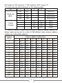
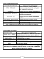
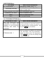
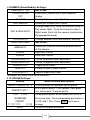
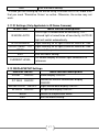
Table of Content:
Chapter 1: Product Summary:
1.1 Technical Parameters…………..………….…………….…………….2
1.2 Package Contents….………………………………………….……….3
1.3 Function description………………………………………….……….3
Chapter 2: Equipment installation:
2.1 DIP switch settings…………………................................................5
2.2 Dome camera structure diagram……………………………….……7
2.3 Bracket installation diagram...……………………………………….8
Chapter3: System OSD menu settings:
3.1 Power-on self-test………….……………..………………………..….8
3.2 Preset point setting and calling…………..……………………..….8
3.2.1 Set preset points………….……………….………..………………..9
3.2.2 Call preset points…….…………………….………….……………..9
3.3 Preset point function table.………………….……………………….9
3.4 <MAIN MENU>………….…………………………..………………….10
3.5 <SYSTEM INFORMATION>.…………………….………………..…11
3.6 <ADDR SETTING>………………..……………………….………..…11
3.7 <MOTION>……………………………………….………………........12
3.7.1 <SET FRAME SCAN>………………………………….……………12
3.7.4 <POWER UP>……………..…………………….…………...………13
3.7.5 <PARK ACTION>……………………………………...………..……13
3.8 <PATTERNS>…..............................................................................14
3.8.1 <PROGRAM PATTERN>.............................................................14
3.9 <CAMERA >(Lens) settings menu................................................15
3.10 <CRUISE> (preset points, cruise settings) menu….…..……....15
3.11 <IR SETTING>...............................................................................16
3.12 <DISPLAY SETUP>.......................................................................16
Chapter 4: Troubleshooting:
4.1 Troubleshooting Table……………..………………..…….....………17
1
Chapter 1:Product Summary:
1.1 Technical Parameters:
Model number
4" High Speed Mini Dome Camera
Optical focus
10X
Image sensor
1/3"CCD
Signal mode
PAL/NTSC
Resolution
Optical focus
Presets
650TVL
Manual/Auto, high performance DSP to utilize high
continuous focusing function.
256
Pattern scan
4groups,each can record 100 actions
Cruise scan
Up to 30 presets cruise with independent dwell
duration.
Other scan
Supports Horizontal scan, Deuce area scan and
random scan
Rotation range
Horizontal 360°unlimited rotation, Vertical 180°, auto
flip
Rotation speed
Horizontal & Vertical Min 0.01° Max 300°/s.
Protocol
OSD
PELCO-D and PELCO-P
Full screen menu
Temperature
control system
Optional
Power supply
DC12V
Ball cover
dimension
4 inch optical glass cover (Non-IR model only)
Material
Aluminum shell
IP Rating
IP66 (Non-IR Model Only)
Work
environment
-20℃~+50℃(select temperature control accessories),
<95%RH
2
1.2 Package Contents:
1. Speed Dome Camera – 1 Pcs
2. Wall Bracket – 1 Pcs
3. Ceiling Bracket – 1 Pcs
4. Power Supply – 1 Pcs
5. User Manual – 1 Pcs
6. Installation Accessories – Lot.
1.3Main Functions Description:
1. Set address coding, baud rate, control protocol:
Each command transmitted to the camera has its own address coding,
baud rate and control protocol. APTZ camera will respond only if its own
address coding, baud rate and control protocol matches the ones of the
command. In order to set the camera address coding, baud rate and
control protocol settings please refer to the DIP settings.
2. Auto speed matching to focal length technical:
Based on user-friendly design, the camera's intelligent response
mechanism will be generate different tracking speeds according to the
proximity of the focal length of the camera. The camera will automatically
adjust the horizontal and vertical tracking speed, so that manual operation
is simpler and track targets become easier.
4. Auto Flip:
When the lens is pulled all the way down (vertically) by the operator, the
lens will auto-rotate 180° and continue the move turning up immediately
after the 90°, this allows a direct watch to the back of the scene in order to
achieve the full 180° continuous vertical surveillance.
5. Set and call preset position:
Preset function stores a given state of the ball. The PTZ memory will store
the horizontal angle; tilt angle and camera lens focal length. "Calling" these
parameters will quickly send the PTZ ball to the saved location. The
operator can quickly and easily store and call preset points by using a PTZ
keyboard, infrared controller or other equipment such as DVR which
supports PTZ feature. The PTZ supports up to 256 preset points.
3
6. Lens Control:
(1) Zoom control
Users can control the PTZ lens in order to adjust the zoom level of the
camera and get wide/narrow view according to the scene.
(2) Focus Control
System default is auto-focus. The object in center of the screen will be the
subject of focus. In exceptional circumstances the user can manually
adjust the focus in order to maintain a clear picture.
When in momentarily manual focus state (achieved by Focus +/- controls
on the control unit), any shift of the camera by user or preset call will
reinstate the auto-focus.
In the following situations the camera lens may not autofocus on the
desired objective:
a. Target is not in the screen center;
b. The target has different parts that are both near and far.
c. The target is light objects such as neon lighting, spotlights and other
luminous items;
d. Target is behind interfering layer (Such as droplets or glass).
e. Large monotone area targets, such as walls.
f. Large area targets, such as walls;
g. Target is located in extremely dark/foggy environment.
7. Aperture Control:
Users can control the lens in order to manually adjust the aperture size to
get the required picture brightness.
8. Backlight Compensation:
When the backlight compensation function is on, the camera will disregard
bright areas in the scene and will open the shutter further more to light up
dark areas in the scene.
9. White Balance:
The camera will reproduce color shadings according to the changes in
ambient light in order to achieve true color shades in any conditions.
4
10. Night Mode (color / Black & White conversion):
Cameras with night mode, automatic color / monochrome conversion mode,
in accordance with changes in ambient light automatic conversion CCD
illumination. Such as: adequate lighting during the day due to the use of
general illumination to ensure colorful images. In the night illumination can
be automatically changed to black and white images show a clear interest.
11. Cruise:
Cruise can be built from several preset points. The presets for this speed
dome can be configured in consecutive order only (you may skip a
non-relevant preset, but you cannot change the order of the called
presets).Dwell durations can be configured according to the needs. The
cruise can be activated using the OSD or the RS-485 controller.
12. Pattern scanning:
Pattern scan will record any movement of the camera's ball in order to
make a consecutive scan with special characteristics.
13. Continuous scan:
Continuous horizontal scan with adjustable height and speed. It can be
triggered in power-up or RS-485 controller.
14. Random Scan:
Random horizontal scan with adjustable height and speed; unlike the
continuous scan, the random scan will shift the camera left and right and
dwell in random points. It can be triggered in power-up, by OSD or RS-485
controller.
15. Area scan
Continuous horizontal scan with adjustable height, speed and left/right
borders which the camera is confined to. It can be triggered in power-up,
by alarm or RS-485 controller.
Chapter 2 Equipment installation:
2.1DIP switch setting:
The four channel DIP switch is the baud rate and the control protocol switch.
The eight channels DIP switch is
the address setting switch.
5
DIP switch to “ON” means to “1”,DIP switch to "OFF" means "0".
The baud rate and control protocol as the following table:
NO.
Baud rate
(BPS)
1
2
3
OFF
OFF
PELCO-P
ON
OFF
PELCO-D
OFF
ON
PELCO-D/P
ON
ON
PELCO-D/P
Control
Protocol
4
OFF
OFF
9600
ON
ON
9600
OFF
ON
4800
ON
OFF
2400
8-bit DIP switch is used to set the camera's address coding. Address set
binary mode can be set to a total of 256 different dome camera address
coding, see coding table address.
Camera address coding form
Camera
address
1
2
3
4
5
6
7
8
0
OFF
OFF
OFF
OFF
OFF
OFF
OFF
OFF
1
ON
OFF
OFF
OFF
OFF
OFF
OFF
OFF
2
OFF
ON
OFF
OFF
OFF
OFF
OFF
OFF
3
ON
ON
OFF
OFF
OFF
OFF
OFF
OFF
4
OFF
OFF
ON
OFF
OFF
OFF
OFF
OFF
5
ON
OFF
ON
OFF
OFF
OFF
OFF
OFF
6
OFF
ON
ON
OFF
OFF
OFF
OFF
OFF
7
ON
ON
ON
OFF
OFF
OFF
OFF
OFF
8
OFF
OFF
OFF
ON
OFF
OFF
OFF
OFF
9
ON
OFF
OFF
ON
OFF
OFF
OFF
OFF
10
OFF
ON
OFF
ON
OFF
OFF
OFF
OFF
11
ON
ON
OFF
ON
OFF
OFF
OFF
OFF
12
OFF
OFF
ON
ON
OFF
OFF
OFF
OFF
…
…
…
…
…
…
…
…
…
246
OFF
ON
ON
OFF
ON
ON
ON
ON
247
ON
ON
ON
OFF
ON
ON
ON
ON
6
248
OFF
OFF
OFF
ON
7
ON
ON
ON
ON
2.2 Dome camera structure diagram:
Figure 1
Figure 2
2.3 Bracket installation diagram
Figure 3
8
Figure 4
Chapter 3 System OSD menu settings:
3.1Power-On Self-Test:
When power is connected to the dome camera, the camera will move in
horizontal and vertical directions to confirm that motors and belts are in order.
The screen will show system-related information.
PTOL: PELCO-D
COMM: 2400,N,8,1
ADDR: 1
Display: PELCO-D protocol、Baud Rate 2400、Address code 1
3.2Preset point setting and calling:
3.2.1 Set Preset points:
(1) Make sure the correct camera is selected in your controller.
(2) Adjust pan, tilt and zoom to the desired location.
(3) Press the required preset number + PRESET* to preserve the scene
preset parameters.
9
3.2.2 Call preset points:
(1) Make sure the correct camera is selected in your controller.
(2) Press the required preset number (inputs the designated preset) +
PREVIEW* button, the camera will immediately move to the desired preset
position. The lens zoom, focus and Iris will also automatically change to the
preset parameters
If the preset input is a special function preset (see "Preset Point table" below),
the dome camera will perform special features functions (such as: Preset 82:
the camera will perform auto-cruise feature).
*Subject to changes according to your controlling device. Please check your
PTZ controller user manual to confirm
3.3 Preset point function table:
Dial the 95thPresets
Dial the 82
nd
Presets
Enter Main menu.
Auto Scan.
th
Clear all presets
th
Pattern Scan 1
th
Pattern Scan 2
th
Pattern Scan 3
th
Pattern Scan 4
th
360-degree gap scan
th
Frame Scan
th
Presets Cruise
th
360 degree continuing Scan
Dial the 83 Presets
Dial the 84 Presets
Dial the 85 Presets
Dial the 86 Presets
Dial the 87 Presets
Dial the 96 Presets
Dial the 97 Presets
Dial the 98 Presets
Dial the 99 Presets
*Subject to changes according to your controlling device. Please check your
PTZ controller user manual to confirm
10
3.4OSD Main Menu
Once the dome camera is power on and finished self-testing, call preset 95in
order to access the ODS main menu as shown in Table 3.1.
MAINMENU
SYSTEM
INFORMATION
Menu function descriptions
Displays camera basic information.
See More Details in section 3.5.
ADDR SETTING
Used to set the camera address.
See More Details in section 3.6.
MOTION
“PTZ” setup menu.
See More Details in section 3.7.
PATTERNS
Pattern scan setting.
See More Details in section 3.8.
CAMERA
Lens setting.
See More Details in section 3.9.
CRUISE SETTING
Preset point cruise setting.
See More Details in section 3.10.
IR SETTING*
Infrared light setting.
See More Details in section 3.11.
DISPLAY SETUP
Screen display setting.
See More Details in section 3.12.
RESTORE FACTORY
DEFAULT
Restore the settings to factory default.
REBOOT SYSTEM
System restart, the dome camera will reset.
EXIT
Exit the OSD menu setting.
*Note:<IR SETTING> is valid only for infrared dome camera model
11
3.5 SYSTEM INFORMATION:
SYSTEM INFORMATION
Menu function descriptions
Serial information, display the dome
camera serial port baud rate, parity, data
bits, stop bits of information.
COM 2400,N,8,1
ADDRESS 1
Display the current dome camera address
Display the current dome camera
communication protocol.
PROTOCOL PELCO-D
Display the current dome camera preset
number.
PRESETS 256
SOFTWARE VERSIONV#.#
Display the current software version.
BACK
Return to main menu.
EXIT
Exit the menu setting.
Note: The system information menu items cannot be modified.
3.6 ADDRESS SETTINGS:
ADDR SETTING
Menu function descriptions
ADDR TYPE HARD
Divides HARD and SOFT; select the SOFT can
directly determine the dome camera address.
ADDR SOFT
1
Within1~254.
ADDR HARD
1
(Configured by DIP Switch)
BACK
RESET
EXIT
Returns to main menu.
To restore the default settings.
Exit the menu setting.
Note: Soft and hard address settings must be identical. Not complying
may cause the camera to go out of control. In such case, restoring to
factory default settings will be required.
12
3.7 MOTION (PTZ) Settings:
This menu is used to set PTZ parameters such as movement and orientation
angles as shown in the following table:
MOTION
Menu function descriptions
SET FRAME SCAN
Set the scan left and right limits.
See More Details in section 3.7.1.
POWER UP NONE
Power on setting menu.
See More Details in section 3.7.4.
PARK TIME
Waiting time before performing idle action.
15S
Which action to perform when the dome
camera is idle.
See More Details in section 7.4.5.
PARK ACTION NONE
FRAME SCAN SPEED
16
Set the area scan speed of the dome camera.
Within1 (Slowest)~32 (Fastest).
RANDOM SCAN SPEED
16
Set the intermittent scan speed of the dome
camera.
Within 1 (Slowest)~32 (Fastest).
BACK
Return to the main menu.
EXIT
Exit the menu setting.
3.7.1 SET FRAME SCAN:
Setting the Left and Right limits of the Frame scan
FRAME SCAN
Menu function descriptions
SET SCAN POSITION
The left and right Limits in Two stages
CLEAR FRAME SCAN
Clear area scanning setting. (Clear left and right
limit position).
BACK
Return to the previous menu.
EXIT
Exit the menu setting.
13
3.7.4POWER UP Settings:
This will define which action the dome camera will perform when it is powered
on. (unless any other action was received). Parameters in the following table:
POWER UP
Menu function descriptions
NONE
Don’t perform any action.
AUTO SCAN
Perform continuous scanning action.
RANDOM SCAN
FRAME SCAN
Perform random scanning action.
Perform frame scan action*
PRESET 1
Send the camera to Preset No.1
PRESET 8
Send the camera to Preset No.8
PATTERN 1
Perform the pattern 1
PATTERN 2
Perform the pattern 2
PATTERN 3
Perform the pattern 3
PATTERN 4
Perform the pattern 4
CRUISE
Perform cruise action*
*Applicable only if these functions are properly set-up.
3.7.5 PARK ACTION Settings:
Park action parameters shown in the following table:
PARK ACTION
NONE
AUTO SCAN
RANDOM SCAN
FRAME SCAN
Menu function descriptions
Don’t perform any action.
Perform continuous scanning action.
Perform random scanning action.
Perform frame scan action*
FRESET 1
Send the camera to Preset No.1
PRESET 8
Send the camera to Preset No.8
PATTERN 1
Perform the pattern 1
PATTERN 2
Perform the pattern 2
PATTERN 3
Perform the pattern 3
PATTERN 4
Perform the pattern 4
REAPEAT LAST
CRUISE
Automatic recovery to last running action (If applicable)
Perform cruise action*
*Applicable only if these functions are properly set-up.
14
3.8PATTERNS Menu:
PATTERNS
PATTERNNUMBER 1
PROGRAM PATTERN
CLEAR CURRENT PATTERN
CLEAR ALL PATTERN
Menu function descriptions
Select pattern number, within 1~4.
To select pattern scan line; Operations
shown in section 3.8.1.
Clear current pattern scan line.
Clear all the pattern lines.
BACK
Return to the previous menu.
EXIT
Exit the menu setting.
3.8.1 PROGRAM PATTERN Menu:
PROGRAM PATTERN
Menu function descriptions
USE THE JOYSTICK OR
KEYBOARD TO MOVE THE
CAMERA TO THE STARTING
POSITION IRIS OPEN TO
CONTINUE
Use the controller to move the camera to
the desired pattern starting position, and
press the IRIS+ key to continue.
STORAGE USED 1
Move the joystick to capture the scanning
line and action, from the movement 1
began to record, up to 100 movements.
Press IRIS+ key to save the settings and
return to table 3-5.
15
3.9CAMERA (Zoom Module) Settings:
CAMERA ID 000
ZOOM DISPLAY
OFF
Not in use
Allow you to remove the Zoom indication
display
BLC OFF
Backlight Compensation Control
AGC MIDDLE
Allows you to adjust AGC levels
DAY & NIGH AUTO
FOCUS AUTO
BAUD RATE 9600
AWB AUTO
Change mode (Day: force the camera to stay in
Day mode, Night : force the camera to stay in
Night mode, Auto: lets the camera to determine
the appropriate mode
Change between Auto and Manual Focusing
Not in Use
Allows you to define the white balance control
of the camera.
R GAIN*
Red Gain Control
B GAIN*
Blue Gain Control
BRIGHTNESS 12
Picture Brightness level adjustment
SHARPNESS OFF
Picture Sharpness level adjustment
MIRROR OFF
HLM OFF
HLM LEVEL FF
Toggle Mirror Effect
Enable/Disable Eclipse feature
Adjust Eclipse effect level
*Available only when AWB set to MANUAL.
3.10 CRUISE Settings*
CRUISE
DWELL TIME[SECS] 6
PRESET LIST 1
1 ON 0 OFF
1234567890
PRESET
1111111111
[1-10]
BACK
Menu function descriptions
Cruise waiting time between preset points.
List of preset points. Total3 pages, each page
can select up to 10 preset points.
Select preset points which need to be active in
the cruise scan. The corresponding parameter is
0 (Off) and 1 (On). Press IRIS+ key to save
change.
Return to the previous menu.
16
EXIT
Exit the menu setting.
*in case you are setting-up the cruise using Provision-ISR DVR, make sure
that you mark “Simulative Cruise” as active. Otherwise, the cruise may not
work.
3.11 IR Settings (Only Applicable in IR Dome Cameras)
IR SETTING
Menu function descriptions
IR MODE AUTO
ON:IR light is forced to be on constantly; OFF:
Infrared light is forced to be off constantly; AUTO:IR
light will switch automatically.
IR ON SENS240
Light intensity for IR light to turn on, within 81~254.
IR OFF SENS 170
Light intensity for IR light to turn off, within 81~254.
BACK
Return to the previous menu.
EXIT
Exit the menu setting.
CURRENT LEVEL
On screen display of current light conditions for
reference
3.12 DISPLAYSETUP Settings
DISPLAY SETUP
ZOOM
ON/OFF
P/T DEG ON/OFF
BRIGHTDATA ON/OFF
Menu function descriptions
Zoom display ON/OFF.
Horizontal/Vertical coordinates display
ON/OFF.
Light source data display ON/OFF.
IR DATA ON/OFF
IR light data display ON/OFF.
BACK
Return to the previous menu.
EXIT
Exit the menu setting.
17
Chapter4: Simple troubleshooting and maintenance.
4.1 Simple Troubleshooting Table:
Failure
Power
connected but
the camera is
not performing
self-test, no
image
Power
connected, the
camera is
performing
self-test, image
available, but
no control
Unable to
complete
self-test, there
are images
associated with
motor tweet
sound
Image
instability
Possible Cause
Solutions
Connected the
wrong power cord
Check voltage in cable
Power supply is
damaged
Check power ratings. Replace
power supply.
Bad fuse
Replace Fuse
Power cord
connection is bad
Confirm firm connections and
polarity.
Dome camera
address, Baud rate
or protocol does not
match
Reset camera and confirm details
with "On screen display" while the
camera is self-testing. If needed
make changes
RS485Connections
Check wiring RS485 control line.
Try switching +/- terminals.
Power rating is not
sufficient
Replace power supply to meet the
requirements of the power
consumption. If the camera is far
from the power supply check cables
for shortages.
Mechanical failure
Replace Camera
Video line
connection is bad
Check Coaxial cable and BNC
clamps
Power rating is not
sufficient
Replace power supply to meet the
requirements of the power
consumption. If the camera is far
from the power supply check cables
for shortages.
18
Blurry Image
Long delays in
actions
performing /
camera going
out of control.
Manual focus on the
state
Make sure settings are on auto
focus. If so try to shift the camera in
any direction to reinstate auto focus
mode
Power rating is not
sufficient
Replace power supply to meet the
requirements of the power
consumption. If the camera is far
from the power supply check cables
for shortages.
RS-485 the signal
attenuation
Check RS-485 Signal Cable.
19