1
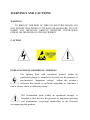
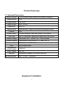
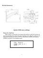
INSTALLATION MANUAL ST-PTZMINI-IR10XTA High Speed Intelligent IR Dome PTZ Color Camera This is a 12 volt DC camera. Copyright North American Cable Equipment WARNINGS AND CAUTIONS WARNING TO REDUCE THE RISK OF FIRE OR ELECTRIC SHOCK, DO NOT EXPOSE THIS PRODUCT TO RAIN OR MOISTURE. DO NOT INSERT ANY METALLIC OBJECTS THROUGH VENTILATION GRILLS OR OPENINGS ON THE EQUIPMENT. CAUTION EXPLANATION OF GRAPHICAL SYMBOLS The lighting flash with arrowhead symbol, within an equilateral triangle, is intended to alert the user the presence of non-insulated “dangerous voltage” within the product’s enclosure that maybe of sufficient magnitude to constitute a risk of electric shock to different persons. The exclamation point within an equilateral triangle, is intended to alert the user the presence of important operating and maintenance (servicing) instructions in the literature accompanying this product. PRECAUTIONS: Persons without technical qualifications should not attempt to operate this dome device before reading this manual thoroughly. Remove any power to the dome before attempting any operations or adjustments inside the dome cover to avoid potential damage to the mechanism. Inside the dome cover there are precision optical and electrical devices. Heavy pressure, shock and other sudden adjustments or operations should be avoided. Otherwise, you may cause irreparable damage to the product. Please DO NOT remove or disassemble any internal parts of the video camera to Avoid normal operation and possibly void the warranty. There are no serviceable parts inside the camera. All electrical connections to the dome should be made in strict accordance with the attached labels and wiring instructions in this manual and in accordance with all local and national electrical codes. Failure to do so may damage the dome beyond repair and void the warranty. For outdoor installation especially in high places or poles, it is highly recommended that the proper lightning arrestors and surge suppressors are installed before the dome is entered into service. Do not use the product under circumstances where the environment exceeds the maximum specified temperature, humidity or power supply specifications. IMPORTANT SAFEGUARDS 1. Read these instructions before attempting installation or operation of this dome. 2. Keep these instructions for future reference. 3. Heed all warnings and adhere to electrical specifications. Follow all instructions. 4. Clean only with non-abrasive dry cotton cloth, lint free and approved acrylic cleaners. 5. Should the clear dome of the camera become dirty, use a special lens cleaning cloth and solution to properly clean it. 6. Do not block any ventilation openings. Install in accordance with manufacturer’s instructions. 7. Use only attachments or accessories specified by the manufacturer. 8. Verify that the surface you are planning to use for attaching the dome can adequately support the weight of the device and mounting hardware. 9. Protect this device against lighting storms with proper power supplies, surge arrestors and other protective precautions. 10. Refer all servicing to SecurityTronix service personnel. Servicing is required when the device has been damaged in any way, when liquid traces are present, or the presence of loose objects is evident or if the device does not function properly, or has received sever impact or has been dropped accidentally. 11. Do not use this product under circumstances exceeding specified temperature and humidity ratings. 12. Avoid pointing the camera directly to the sun or other extremely bright objects for prolonged period of time avoiding the risk of permanent damages to the imaging sensor. 13. The attached instructions are for use by qualified personnel only. To reduce the risks of electric shock, do not perform any servicing other than contained in the operating instructions unless you are qualified to do so. 14. During usage, the user should abide by all electrical safety standards and adhere to electrical specifications for the operation of the dome. The control cable for RS485 communications as well as the video signal cables should be isolated from high voltage equipment and high voltage cables. 1 Carton Contents IR Speed dome 1pc Wall mount bracket 1pc Screws kit 1pc User manual 1pc 1 Product Summary 1.1 Technical Parameters Model number 4 INCH MINI HIGH SPEED IR DOME CAMERA Optical focus 10X Image sensor 1/4"CCD Signal mode PAL / NTSC Resolution Optical focus Presets Pattern scan Tour scan 650TVL Manual/Auto, Digital continuous focusing function. 256 4 Scan Patterns, each can record 100 actions Up to 30 presets. Speed and dwell time can be set. Rotation range Horizontal 360°, Vertical 180°, auto reverse Rotation speed Horizontal & Vertical Min 0.01° Max 300°/s. Communications OSD Temperature control system Power supply Material Environmental PELCO-D and PELCO-P Full screen menu Optional DC12V Aluminum & plastic, for indoor use only -4F ~ +122°F <95%RH Equipment installation 2 Setting the Address, Baud Rate and Protocol This camera uses the On-Screen Menu to change communication settings. This is called “Soft Addressing”. The camera comes from the factory with the default settings of: Address: 1 Baud Rate: 2400 Protocol: Pelco D To Change the settings, use a PTZ controller set the above settings to access the camera’s menu by calling Preset 95, then use the menu as indicated in TABLE 3-3 on page 7 of this manual. Dome camera dimensions 3 Bracket dimensions System OSD menu settings Power-On / Self-Test When power is connected, the camera will perform a self-test function by panning and tilting the camera as well as testing zoom. After the self-test, the camera will display the Protocol (PTOL), Baud Rate (COMM) and Address (ADDR) as shown in the diagram below. PTOL: PELCO-D COMM: 2400,N,8,1 ADDR: 1 4 Storing (saving) preset points: Using a PTZ controller, aim the camera at the desired subject and adjust zoom if desired. To store the preset in the camera, consult the manual for the specific PTZ controller you are using for how to store a preset. Sometimes storing a preset is referred to as “writing”, “saving”, “setting” or some other similar term. For instance, on a SecurityTronix ST-PTZMINI-KB controller, the button sequence to STORE preset 1 on a camera is: Press “SET”, press “1”, press “PRE”. Calling preset points: Normally, “calling” a preset will cause the camera to move to the position it was at when that preset number was stored. There are a few exceptions, such as the preset numbers which are reserved for special functions, as listed in the table below. To “CALL” a preset in the camera, consult the manual for the specific PTZ controller you are using for how to call a preset. For instance, on a SecurityTronix ST-PTZMINI-KB controller, the button sequence to CALL preset 1 on a camera is: Press “1”, press “PRE”. Preset point function table: Call Preset 95 Enter the On-Screen menu. Call Preset 82 Auto Cruise Call Preset 83 Clear all presets Call Preset 84 Start Pattern scan 1 Call Preset 85 Start Pattern scan 2 Call Preset 86 Start Pattern scan 3 Call Preset 87 Start Pattern scan 4 Call Preset 96 360-degree scan with 90° stops Call Preset 97 Scan between two presets Call Preset 98 Presets cruise Call Preset 99 360 degree continuous scan 5 <MAIN MENU> To access the camera’s On-Screen Display (OSD) menu, “call” preset 95 using your PTZ controller and the Main Menu screen will appear: MAIN MENU Menu function descriptions SYSTEM INFORMATION Displays basic camera information. ADDR SETTING Used to set the camera address. MOTION “PTZ” setup menu. PATTERNS Manual scan settings CAMERA Lens settings CRUISE SETTING Preset point cruise settings IR SETTING Infrared light settings DISPLAY SETUP Screen display settings RESTORE FACTORY DEFAULT Restore the factory default setting. REBOOT SYSTEM System restart. EXIT Exit the OSD menu setting. <SYSTEM INFORMATION> SYSTEM INFORMATION COM 2400,N,8,1 ADDRESS PROTOCOL PRESETS 1 PELCO-D 256 Menu function descriptions Displays the camera’s current Baud Rate Displays the camera’s current Address Displays the camera’s current Protocol Displays the currently selected preset SOFTWARE VERSION V5.2 Displays the current software version. BACK Return to main menu. EXIT Exit the menu Note: The system information such as Address, Baud Rate, etc shown on this menu cannot be changed on this menu page 6 <ADDR SETTING> ADDR SETTING ADDR TYPE ADDR SOFT ADDR HARD (1) BACK RESET EXIT Menu function descriptions Sets either HARD and SOFT addressing; Choosing HARD will set the dome to address 1. Choosing SOFT allows the address to be set in the menu, below. If SOFT is selected above, enter the desired address here. The address range is 1~254. Always displays the DIP switch address (1) Returns to main menu. Restore the factory default settings. Exit the menu Note: Immediately after setting a new “soft address” the camera will no longer respond on the previous address. Make sure to set the PTZ controller to the new address to regain control of the camera. Access to the internal DIP switches requires extensive disassembly of the camera. It is highly recommended to use “soft” addressing. <MOTION> MOTION SET FRAME SCAN Menu function descriptions Set the left and right limit points for a LR scan. POWER UP Set which action the camera performs on boot-up. PARK TIME How long the dome must sit idle before the PARK ACTION is taken. PARK ACTION FRAME SCAN SPEED RANDOM SCAN SPEED Perform an action when the camera is idle. Set the L/R scan speed of the camera. Range: 1 (Slowest) ~32 (Fastest). Set the intermittent scan speed of the camera. Range: 1 (Slowest) ~32 (Fastest). BACK Return to the main menu. EXIT Exit the menu setting. 7 <SET FRAME SCAN> (L/R scan) FRAME SCAN Menu function descriptions SET SCAN POSITION Set the Left & Right scan limit positions CLEAR FRAME SCAN Clear left and right limit positions BACK Return to the previous menu EXIT Exit the menu SET SCAN POSITION SET FRAME SCAN LEFT LIMIT POSITION IRIS OPEN TO CONTINUE SET FRAME SCAN RIGHT LIMIT POSITION IRIS OPEN TO CONTINUE CLEAR FRAME SCAN CLEAR FRAME SCAN IRIS OPEN TO CONTINUE Menu function descriptions Operate the PTZ controller to select the left limit position; Press IRIS+ button to confirm the current position of the left limit, and the menu will prompt to set the right limit position (below) Menu function descriptions Operate the PTZ controller to select the right limit position; Press IRIS+ button to confirm and return to the previous menu. Press IRIS+ to clear the left and right limit positions and return to the previous menu 8 <POWER UP> This menu sets which action is performed when the camera powers up. It’s useful if there are known issues with blackouts etc. POWER UP Menu function descriptions NONE Don’t perform any action. AUTO SCAN Perform continuous scanning action. RANDOM SCAN Perform intermittent scanning action. FRAME SCAN Perform area (L/R) scanning action. PRESET 1 Call preset point number 1. PRESET 8 Call preset point number 8. PATTERN 1 Perform pattern scan 1 PATTERN 2 Perform pattern scan 2 PATTERN 3 Perform pattern scan 3 PATTERN 4 Perform pattern scan 4 CRUISE Perform the cruise scan of preset points. <PARK ACTION> This menu sets which action the camera should perform if it sits idle (no user input) for a predetermined amount of time. PARK ACTION Menu function descriptions NONE Don’t perform any action. AUTO SCAN Perform continuous scanning action. RANDOM SCAN Perform intermittent scanning action. FRAME SCAN Perform area (L/R) scanning action. FRESET 1 Call preset point number 1. PRESET 8 Call preset point number 8. PATTERN 1 Perform pattern scan 1 PATTERN 2 Perform pattern scan 2 PATTERN 3 Perform pattern scan 3 PATTERN 4 Perform pattern scan 4 REAPEAT LAST Repeat the last action performed before going idle. CRUISE Perform the cruise scan of preset points. 9 <PATTERNS> PATTERNS PATTERN NUMBER PROGRAM PATTERN CLEAR CURRENT PATTERN CLEAR ALL PATTERN BACK EXIT <PROGRAM PATTERN> PROGRAM PATTERN USE THE JOYSTICK OR KEYBOARD TO MOVE THE CAMERA TO THE STARTING POSITION. PRESS IRIS OPEN TO CONTINUE PATTERN STORAGE USED 1 Menu function descriptions Select pattern number. Range: 1~4. Used to program a pattern scan. The menu will prompt the user through the steps Clear current pattern data. Clear the data for ALL patterns. Return to the previous menu. Exit the menu Menu function descriptions Use the joystick or keyboard to move the camera to the starting position, and press the IRIS+ key to continue. Menu function descriptions Operate the PTZ controller to begin recording movements. The count starts at 1 and records up to 100 movements. Press IRIS+ key to save the motion and return to the previous menu. 3.9 <CAMERA> (Lens settings) Languages Multiples Display AGC Backlight compensation Shutter setting Focus setting Brightness setting Sharpness Setting Day& night switch Negative Set Lens Set Default setting 10 Chinese/English ON/OFF 180 ON/OFF AUTO AUTO 110 013 AUTO OFF OFF OFF <CRUISE> CRUISE DWELL TIME (seconds) PRESET LIST 1 = ON 0 = OFF 1234567890 PRESET 1111111111 [1-10] Menu function descriptions How long the camera waits on each preset point. Cruise list of preset points. There are 3 pages, each page can contain 10 preset points. Select preset points are included in the cruise scan (tour). Press IRIS+ key to change, 1 is selected, 0 is skipped. BACK Return to the previous menu. EXIT Exit the menu. <IR SETTING> IR SETTING IR MODE AUTO IR ON SENS IR OFF SENS Menu function descriptions ON: IR light is always on; OFF: IR light is always off; AUTO: IR light is switched on and off automatically. Sets brightness level at which the IR LEDs will turn on. Range: 81~254. Sets brightness level at which the IR LEDs will turn off. Range: 81~254. BACK Return to the previous menu. EXIT Exit the menu setting. 3.12 <DISPLAY SETUP> DISPLAY SETUP ZOOM ON/OFF P/T DEG ON/OFF BRIGHT DATA ON/OFF IR DATA ON/OFF BACK EXIT Menu function descriptions Zoom display ON/OFF. Horizontal/Vertical angular coordinate display ON/OFF. Light source data display ON/OFF. IR light data display ON/OFF. Return to the previous menu. Exit the menu setting. 11 TROUBLESHOOTING No picture after applying power – (i) check all plugs and cables are connected to the proper connectors: (ii) ensure your power supply is providing the correct voltage and enough current. The picture has ripples – (i) Check to see if the power supply is experiencing AC ripple. If so, a filter may be required. (ii) Determine if the monitor is faulty. (iii) Determine if other peripheral equipment is causing the ripple and if so make the necessary adjustments. The picture background continuously changes color – A fluorescent lamp’s magnetic field may cause color roll. If possible, increase the distance between the camera and any fluorescent lamps in the vicinity. The picture appears smeared – (i) The power supply voltage level may be unstable. Try another power supply. (ii) Ensure the cables are correctly connected and of the right impedance (75 ohms). Other interference may require the use of a SecurityTronix ground loop isolation filter. Power is on but the controller does not work – (i) Check to make sure the DIP switches or software addressing are all set correctly for address, baud rate and protocol. (ii) Check that the RS485 wires at the camera and controller have correct polarities. The camera colors are: Blue = A (+), Green = B (-). (iii) Check the integrity and continuity of the Unshielded Twisted Pair (UTP) cable. Additional troubleshooting assistance can be found online at www.securitytronix.com or email us at [email protected] or call (800) 688-9282 – Press “3” for tech support then “2” for SecurityTronix 12