1
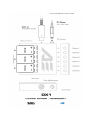
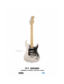
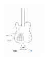
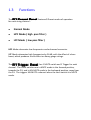
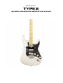
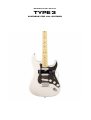
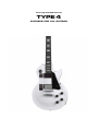
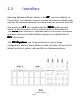
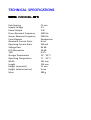
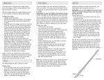
2015 AEScHER EUROPA D1 - DRONE User Manual D Series rev. 3.0 1 1.1 1.2 1.3 1.4 SET UP Overview Power Supply Functions Versions 2 2.1 2.2 2.3 2.4 2.5 OPERATION Instrument Compatibility Mounting Controllers Onboard Effects Maintenance 1 SET UP 1.1 Overview The SRG D Series are a line of instrument mounted, externally powered string resonators, based on nano scale SMDI architecture Available in monophonic and polyphonic models. The D1 The ● ● ● ● ● ● DRONE is a 6 channel polyphonic resonator for guitar. SRG D1 DRONE package includes : D1 DRONE Surface Mounted String Resonator XL6- U Above String Divided String Sensor Kit DX1 Power Supply / Channel Expander Auxilliary 1300 mA 12 V DC Adapter (3x) 9 Volt Alkaline-Manganese Primary Cells Mounting Velcro The D1 features 6 highly inductive, low resonant frequency sensor coils, and 6 highly inductive driver coils, directly wound on high flux density neodymium core magnets. The D1 also features 6 ultra bright - deep blue LED power indicators. SET UP > After unpacking the box, remove the 2 backing strips from the mounting velcro for the D1 Transducer Module and apply the velcro to the instrument, directly under the strings, ideally below the instrument neck pickup, with the strings aligned with the LEDs on the D1 Transducer Module - as illustrated on page 9. After applying the velcro strips – mount the D1 Transducer Module, with the LEDs pointing towards the fingerboard. Each of the 6 LEDs should align with the string below it. The D1 should have a string clearance of at least 1 mm after mounting. It may be necessary to adjust the height of the saddles. Next – plug the Trigger Module into the 12 pin socket on the left side of the D1 Transducer Module. Then - remove the backing strip from the padding velcro for the Control Module, and apply the velcro strip to the space to the right of the D1 Transducer Module, then plug the 34 pins on the Control Module into the 34 pin socket on the right side of the D1 Transducer Module. After fully mounting and connecting the D1 System - remove the backing strips from the mounting velcro for the DX1 Power Supply. Apply the adhesive velcro strips to the back of the body – in 'any suitable location' on the front of back of the instrument. Before connecting the DC cable - check that the Master Power Switch on the Control Module is in the OFF position. Then mount the DX1 Power Supply. Slide the three 9 volt batteries into the battery connector. - as illustrated on page 7. Then onnect the DC cable first to the Control Module and then to the DX1 Power Supply. The XL6-U mounts with velcro on top of the Control Module with the XL6-U extending over the strings as a cantilever. The cable is hardwired to the XL6-U and the 13-pin DIN connects to the DX1 Channel Expander on the back of the instrument, or to the VX adapter. The D1 DRONE Trigger Module features 6 onboard channel switches and 6 channel triggers - easily accessable during performance. The Preset Module has 6 channel mode preset controls for Normal Mode – HPF Mode and LPF Mode. To Enable Normal Mode, slide upper and lower switches towards each other. To Enable LPF Mode, slide upper and lower switches towards the player. To Enable HPF Mode, slide upper and lower switches towards the stage. The D1 is fully operational the moment the 6 blue power LEDs are illuminated. The DX1 Power Supply / Channel Expander may be mounted on the front or back of the instrument. Optionally - a 12 volt 1300 mA DC adapter may be used as an alternative power supply, with the DX1 used only as a channel expander. 1.2 Power Supply The DX1 features an ultra-fast slide-in battery compartment for three 9 volt primary cells. Eliminating the frustration of fumbling in the dark with clumsy floppy wire 9 volt battery connectors, the slide mount battery port allows rapid battery changes in as little as 5 seconds. The 3 batteries are connected in parallel, and will discharge together at a constant rate. Always check that the master power switch on the Preset Module is in the OFF position before installing the batteries. and that the + polarity is correctly orientated – as illustrated on page 7. Slide the included 9 Volt Batteries into the battery compartment until firmly connected. If the LEDs do not light, or flicker – either 1 or more batteries are not firmly connected, or 1 or more batteries may be weak or dead. The DX1 includes three 9 volt Alkaline-Manganese primary cells, which are safely disposable. Under No Circumstances is the battery to be recharged or dismantled. The storage life of the battery is 5 years. Do not install a rechargeable NiMH battery, as rechargeable 9V batteries actually supply only 8.4 volt rather than 9 volt. The D1 requires a full 9 volt at 330 mA for stable operation. WARNING - Damage resulting from the use of rechargeable batteries, oversized batteries or incorrect installation can invalidate the warranty ! 1.3 Functions The D1 Preset Panel features 3 Preset modes of operation for each string channel : • Normal Mode • HPF Mode ( high pass filter ) • LPF Mode ( low pass filter ) HPF Mode attenuates low frequencies and enhances harmonics. LPF Mode attenuates high frequencies by 26 dB, with the effect of a bass boost, which produces a cello effect on heavy gauge strings. The D1 Trigger Panel has 1 MUTE switch and 1 Trigger for each channel. The Latch switches are in MUTE mode in the forward position, towards the D1, and in UN-MUTE mode in the backward position, away from the D1. The triggers UN-MUTE a channel when the latch switch is in MUTE mode. 1.4 The D1 Versions DRONE is available in 4 standard versions : TYPE 1 SUITABLE FOR TELECASTER STYLE GUITARS Mirror Versi on TYPE 2 SUITABLE FOR STRATOCASTER STYLE GUITARS Pedal Controller Versi on TYPE 3 SUITABLE FOR ALL GUITARS Internally Installed Versi on TYPE 4 SUITABLE FOR ALL GUITARS 2 OPERATION 2.1 Instrument Compatibility The SRG functions on any guitar with ferromagnetic strings, including plain steel strings and steel core strings, and a bridge saddle spacing of 12 mm. The SRG D Series are also capable of driving Acoustic Steel String Instruments. 2.2 Mounting The SRG D Series includes both internally mounted and surface mounted models. The D1i is an internally mounted SRG which requires permanent installation by a professional Luthier. The D1 is a surface mounted SRG designed to be quickly and easily mounted without modification to the instrument, using self-adhesive velcro. The XL6-U 'Above String' Divided String Sensor mounts over the drivers on the D1 Transducer Module. The XL6-U Kit includes the VX Adapter for the Roland VSystem. 2.3 Controllers Operating Modes and Master Power on the D1 are controlled by the Preset Panel. Each individual channel resonator will initiate immediately after switching the channel power switch or channel trigger on the Trigger Panel ON. Alternatively the D1 can interface with the D1X pedal controller, which has all the functions of the mounted system in foot pedal form. The D1X pedal controller is recommended for the Fender Stratocaster and other instruments with insufficient space on the right side for the D1 control panel. The D1 System can also be produced in a mirror image configuration, with the Trigger Module on the right side, and the Control Module on the left, which works perfectly on Stratocaster guitars. 2.4 Onboard Effects The D1 has 2 Effects: • HPF Mode ( high pass filter ) Harmonic • LPF Mode ( low pass filter ) Bass Boost Optionally - The D1 can also be produced (on request) with Hyperdrive which engages a bank of 6 x 1 Watt M21 Resonator Engines. 2.5 Maintenance If possible - always store the SRG in a dry, dust-free environment at room temperature (15 - 20° C). Always remember to turn the Master Power Switch on the D1 OFF when not in use. Clean the SRG using a soft cotton cloth or t-shirt soaked in warm water. Never attempt to clean any part of the SRG with alcohol, acetone, ammonia, or any household cleaner! TECHNICAL SPECIFICATIONS SRG MODEL D1 Pole Spacing Supply Voltage Power Output Driver Resonant Frequency Sensor Resonant Frequency Core Magnets Quiescent Current Drain Operating Current Drain Voltage Gain LPF Attenuation THD Storage Temperature Operating Temperature Width Length Height (mounted) Height (without velcro) Mass 11 mm 9V 3W 2300 Hz 2300 Hz Neodymium 8 mA 330 mA 46 dB 26 dB 0.2% 15° - 25° C 0° - 35° C 161 mm 124 mm 11 mm 9 mm 280 g