1
User Manual
Go to Introduction Page
Go to Contents Page
www.performanceproducts.co.uk
Introduction
Congratulations on buying a Snooper Safety Alert System!
This user manual aims to provide you with installation and user
instructions for the Snooper Evolution GPS location device.
The Snooper Evolution utilises the very latest Global Positioning Satellite
(GPS) technology, which has been designed to help you drive safely
within the confines of today’s speed limits by alerting you quickly, and
easily to the presence of police speed traps, often located at accident
black spots. The geographical coordinates of all ‘fixed’ speed monitoring
systems and many officially designated accident ‘hotspots’ have been
stored on a database (powered by Enigma) that is constantly monitored
and updated by our data collection team, ensuring that you are alerted to
every potentially hazardous stretch of road or danger spot
The Evolution connects quickly and easily to your PC so that you can
download the database in a matter of minutes (internet connection
required). Please note that a certain level of system hardware and
software are required on your PC; see the section Software CD later in
this manual. Alternatively a special external modem may be obtained so
that a download can still be performed even when you do not have
access to a PC. Once the database has been downloaded your Evolution
compares your position using its built-in GPS antenna, with the position
of every known ‘fixed’ speed monitoring system and accident ‘hotspot’
alerting you both audibly and visually via a speaker and LED text display
ensuring your highest concentration at all times.
The Evolution also comes with a laser detector built into the unit. A
combination of a detection lens at the rear of the unit and a 360-degree
prism on the top of the unit ensures all round protection. It has been
designed to detect laser speed monitoring systems often used in danger
spots where 'fixed' systems cannot be easily utilised.
Drive Safely with Snooper!
The Snooper Evolution has been designed and manufactured to help
enhance road safety and is in no way a licence to speed nor has it been
designed as a substitute for concentration. Driving within the speed limit,
whilst carefully observing current road conditions is essential.
2
Contents
Page
Components
Features
Registering your Snooper Evolution
Software CD
Downloading & Uploading
Installation
Operating Instructions
Starting Up
Standby Screen
15 Adjusting the Volume
MODE/MENU Button
Cancel Button
16 Mute Button
Alert Patterns
18 How Laser Works
19 Saving New Co-ordinates
20 Deleting Stored Co-ordinates
21 Tone
Warning Selection
Brightness
Set Time
22 Voice Alerts
User Stored Alerts (MEM Edit)
Smart Mute
23 Logic Modes
Speed Limit
24 Speed Unit
Pre-Alert Setting
Radar/Laser Settings - S100-RLD Only
25 Motorcycle Installation
26 Troubleshooting
30 Specification
30 Accessories & Price List
31 Service under Warranty
4
5
6
7
8
9
14
IMPORTANT - READ FIRST - IMPORTANT
You must register your Evolution before use. It will not be possible
to perform downloads until registration has been completed. See
'Registering your Snooper Evolution' on page 6 for further details
3
Components
Snooper Evolution
The following components come as standard with your Snooper Evolution:
1 x Snooper Evolution system
1 x Windscreen suction cup bracket
1 x Hook and loop fastener
1 x Coiled power lead with cigarette lighter socket adaptor
1 x Straight 2M hard wire lead
1 x RS232 PC connecting cable
1 x RS232 to USB conversion lead
1 x 240v AC to 10v DC mains power adaptor
1 x Download Software Disc
PLEASE NOTE
Due to our desire to continually improve our products, specification
may change without notice.
Return to Contents Page
4
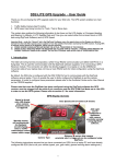
Features
5
NEW LOCATION
MODE/MENU
MUTE
/CANCEL
1
SELECT
3
2
4
5
DC 12V
8
6
7
5
RS232
RD
9
10
5
OFF 2
POWER ON/OFF
EAR
12
11
1
2
3
4
5
6
7
MODE, MENU & Scroll Button
MUTE, CANCEL & Scroll Button
New Location & Select Button
LED Text Display
3600 Laser Prism
Rear Laser Sensor
Windscreen Bracket Mounting Slot
Return to Contents Page
8 12v Power Input Socket
9 RS232 Computer Interface Socket
10 S100 RLD Input Antenna Socket
(S100 RLD not inc)
11 Power On/Off & Volume Control
12 Earphone Socket
(Earphone not inc)
5
IMPORTANT PLEASE READ BEFORE USING
YOUR SNOOPER EVOLUTION!
The database built into your Snooper Evolution is unpopulated when
purchased for security reasons. As a result you must register your unit
before you are able to complete any downloads. There are four ways to
register your unit.
Register On-line
Go to the official Snooper website www.snooperneo.co.uk and register
your unit on-line. Your unit should normally be activated within 30 minutes
of registration.
By Telephone
You can contact us by telephone on 0870 787 0700 between the hours of
9.00am and 5.30pm, Monday to Friday. Your unit should normally be
activated within 1 hour of registration.
By Fax
Complete the registration form included with your Snooper Evolution and
fax it to 0870 787 1700 between the hours of 9:00am and 5:30pm
Monday to Friday. Your unit should normally be activated within one hour
of registration.
By Post
If you would like to register by post send the completed registration form
to us at the following address.
Performance Products Ltd
Cleaver House, Sarus Court, Stuart Road,
Manor Park, Runcorn, WA7 1UL
If you register by post your unit should normally be activated within 24
hours upon our receipt of your completed registration form.
Please Note: To register your Evolution you will need the serial
number of your unit and you are required to select a payment
method at the time of registration. There are two payment options
available:
Monthly by Direct Debit - Receive 6 Months FREE, then pay only
£4.95 a month. Pay only £4.95 inc VAT in easy to manage monthly
payments. Direct Debit payments only start after the initial FREE 6 month
period has expired.
One up-front payment of just £99.95 for 30 Months of Downloads
Pay one payment of just £99.95 Inc VAT, by credit card, debit card or
cheque and save £20!
PLEASE NOTE
Due to our desire to continually improve our products, specification
may change without notice.
Return to Contents Page
6
Before you can begin downloading the database onto your Snooper Evolution you
will need to install the driver software (if using the RS232 to USB Conversion
lead) and the Snooper Evolution Updater software that enables you to do this.
There is a certain minimum hardware and software requirement needed in order
for the software to be installed and used successfully.
Hardware Requirements
The computer must have an Intel Pentium Class processor or equivalent, a
minimum of 32MB of RAM, a monitor with 256 (8 bit) colours or greater, a CD
ROM drive, 20MB of free disc space and a spare RS232 connection.
Software Requirements
The software will only operate on the following Windows based operating
systems: Windows 98 Second Edition, Windows Millennium, Windows 2000,
Windows Xp and will only work with Internet Explorer 4.5 or Netscape Navigator
4.5 or above.
NOTE: The Snooper Evolution Updater software does not support Windows
95 and Apple Macintosh operating systems.
Installing RS232 to USB Conversion Lead
1. Place the Software CD into the CD ROM drive. When the auto-run menu is
displayed, click close.
2. Insert USB lead into a spare USB port; the ‘Add New Hardware’ wizard will be
displayed.
3. Select the option for the wizard to search for the driver automatically and click
‘Next’.
4. If a Digital Signature warning message is displayed select ‘Continue Anyway’.
5. The Wizard will inform you when the hardware is installed.
6. If you have any difficulty in installing the lead please refer to the Step By Step
Guides on the CD.
Software Installation Instructions
Place the Software CD into the CD ROM drive. Your PC should automatically
open a window displaying the instructions for installing the software. To begin
installation, click the 'Install' button and follow the installation instructions to install
the download software.
To launch the CD manually: Click on Start and then Run. In the dialogue box that
opens click on Browse - another dialogue box will open. Locate your CD ROM
drive (drive letter is normally D) using the 'Look in' option and select 'Menu' from
the lower portion of the dialogue box. Once you have selected 'Menu' click on
Open on the explorer box and then OK on the Run dialogue box. Any later
software updates or packages can be obtained from www.snooperneo.co.uk. If
you have any problems using this software please call 0870 787 0700 during
office hours and select Option 3.
Once the software is installed you are ready to download the database to
your Evolution. Double-click the icon 'Snooper Evolution Updater' that now
appears on your desktop to launch the program and follow the onscreen
instructions.
Return to Contents Page
7
SOFTWARE CD
Software CD
Downloading
Performing a download is simple.
1 Connect either the RS232 lead or the USB lead (with the RS232 lead attached) to your
computer and plug the other end of the lead into your Evolution in the socket marked RS232.
2 Connect the AC Power adapter to a mains plug socket and attach the other end to the
Evolution in the socket marked DC 12V.
3 Power up the Evolution by turning the rotary on/off switch towards you and connect the
computer to the Internet.
4 Open up the Snooper Evolution software by double-clicking on the desktop icon. Select the
COM port* the Evolution is connected to from the drop down list and then select which data
you want to download (Cameras only or Cameras and Schools).
* If using the RS232 cable this is usually COM 1. If you are using the RS232 to USB converter
you should check which COM port has been allocated to the USB device by Windows. This
information can be found in the computers ‘Device Manager’ under the heading Ports (COM &
LPT). The device is named ‘Prolific Serial to USB’ and the COM port number is shown in brackets.
On the Evolution:
5. Press and hold the MODE/MENU button on your Evolution until the screen reads ‘Tone’.
6. Press the MUTE/CANCEL button twice until the screens reads ‘Download’.
7. Press the SELECT button twice, the screen will now read ‘Connect’.
8. Click START UPDATE on the software.
The download process is as follows:
• The software will display the serial number of your Evolution and a red progress bar will start
to progress across the screen.
• The software will then connect to the database server and then download** the database.
• The data will then be sent to the Evolution unit.
• The Evolution will then save the data received.
• Once the download is complete the Evolution will beep and ‘Success’ will briefly be displayed.
**If you have a Firewall on your computer the Firewall software will inform you that the Snooper
Updater software is trying to access the internet. Please make sure that you grant/allow/permit
access through the Firewall. Please read the messages supplied by your Firewall software
carefully before choosing your option. If you do not allow the program to access the internet
through the Firewall, the download process will fail. Please note: Windows XP SP2 comes with a
built-in firewall as standard.
Uploading
Once the data has been saved onto the Snooper Evolution you are given the opportunity to
upload coordinates if in the unlikely event you should discover a Safety Camera location not
already in our database (See Operating Instructions on how to save a new location).
Uploading can be performed once the message ‘Upload Y’ is displayed. Using either the
MODE/MENU or the MUTE/CANCEL buttons on your Evolution, select ‘Y’ or ‘N’ and press the
SELECT button. If you have no coordinates to send to us select ‘N’.
If verification proves to be positive the coordinates will then be added to our master database.
Please note: Once the coordinates have been uploaded please be aware that these coordinates
will need to be deleted in order for your unit to use the database locations rather than the user
stored locations.
As there are constant additions to our database you will need to perform regular downloads. The
frequency with which you do this is entirely up to you, but we recommend that higher mileage
drivers often driving on unfamiliar roads download once or twice a week whereas lower mileage
drivers perform a download once or twice per month.
Please Note: Your unit MUST be registered before you can perform a download.
Return to Contents Page
8
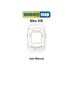
Installation
For best results mount the Evolution onto the vehicles windscreen,
although it can be mounted on the dashboard with the hook and loop
fastener.
When installing your Snooper Evolution please ensure that:
• The unit, with its built in GPS antenna has a clear view of the sky*
• It is located in a position where you can easily view the LED text display
without having to take your eyes too far from the road ahead and that
you can reach the controls safely.
• Does not interfere with the vehicles controls
• Does not jeopardise the drivers or passengers safety
• You will be able to remove the device to perform downloads.
*Please Note: Some vehicles including Renault, Citroen and Peugeot may
come with a ‘Heat Reflective’, ‘Metal Oxide’ or ‘Comfort’ windscreen which
may affect the performance of the built in GPS antenna. If you are unsure
what type of windscreen is fitted to your vehicle then contact your local
vehicle dealer or manufacturer for further information. In these situations
you will need to purchase a re-radiating antenna, which can be positioned
either on the rear parcel shelf or outside the cabin of the vehicle.
Once you have found a suitable location for your Evolution secure it in
place by using either the suction cup windscreen bracket provided or the
‘Hook and Loop’ fastener. More detailed installation instructions follow.
Windscreen
Dashboard
RS232
RD
PLEASE NOTE: Be careful to choose a location that does not block the
drivers view or where it might endanger the driver or passengers should
your vehicle suddenly come to a stop or be involved in an accident.
DO NOT leave the unit on the mounting bracket when the car is
stationary during hot conditions. Exposing the Evolution to extremely
high temperatures can temporarily impair performance. Keep the
Evolution out of sight when not in use to help avoid potential theft.
Return to Contents Page
9
Installing your Snooper Evolution using the Hook and Loop fastener
Your Evolution can be installed easily with the hook and loop fastener if
you have a sufficiently flat area on your dashboard. Please remember
that you need to connect the power connection cable as well as ensuring
that you can read the LED text display and reach the controls safely.
Follow these instructions to mount the control panel in this way.
- Use a damp cloth to thoroughly clean the bottom of the Evolution and
the area where you intend to mount your unit.
- With the two parts of the Hook and Loop fastener still fastened together,
peel the backing tape from the softer 'Loop' side of the fastener and
apply it to the bottom of the unit.
- Next remove the backing tape from the 'Hook' side of the fastener,
again whilst the two parts are still fastened and position the unit onto
the desired area. If possible leave the Hook and Loop fastener for 24hrs
to adhere properly before using regularly.
- Finally plug the smaller plug on one end of the power cable into the
socket marked DC12V on the back of the Evolution and plug the larger
plug into the cigarette lighter socket of your vehicle. Your Snooper
Evolution is now ready for use. For further information please read the
section on Power Connection on page 12
Return to Contents Page
10
Installing your Snooper Evolution using the Windscreen Suction
Cup bracket
You can mount your Evolution to the inside of your vehicles windscreen
using the suction cup windscreen bracket provided. Simply select a
position within the windscreen so that the top of the unit has a clear view
of the sky, remembering that you need to connect the power connection
cable as well as ensuring that you can read the LED text display and
reach the controls safely
- Install the suction cups onto the bracket by fitting them into it's holes.
- Clean the area where you wish to position the bracket thoroughly with
a good quality glass cleaner.
- Carefully bend the bracket so that when it is mounted on to the
windscreen with the Evolution attached, the Control Panel is facing in
the desired direction so that you can easily see the LED display and
safely operate the controls.
- Slide the Evolution onto the bracket until it is secure.
- To remove the Evolution simply slide the unit off the bracket from the
front.
RS232
RD
- Finally plug the smaller plug on one end of the power cable into the
socket marked DC12V on the back of the Evolution and plug the larger
plug into the cigarette lighter socket of your vehicle. Your Snooper
Evolution is now ready for use. For further information please read the
section on Power Connection on page 12.
Return to Contents Page
11
Power Connection
Using the cigarette lighter socket
The Evolution comes with a power cable designed to plug into your
vehicles cigarette lighter socket. Take the lead and plug the smaller end
into the DC 12v input socket on the back of the Evolution and plug the
cigarette lighter adaptor into your vehicles cigarette lighter socket.
Please Note: Do not leave your Evolution plugged into the cigarette
lighter socket when you start your vehicle. The cigarette lighter socket is
prone to power surges as the vehicle is started and this may cause
damage to your unit.
If the device does not power up please check that the cigarette lighter
socket is clean of any debris, remembering not to insert any metal objects
into the socket, check that the cigarette lighter adaptor is inserted all the
way into the socket and to check that the fuse in the cigarette lighter
adaptor is operational. If your Evolution will still not power up, please
check that the cigarette lighter in your vehicle is functioning correctly.
Replacing the Fuse
If the Evolution stops operating, the fuse in the cigarette lighter plug may
have blown. If it has blown, follow these steps to replace it with a 2 amp,
5 x 20mm, fast acting fuse.
Caution: Using a fuse that does not meet these ratings or defeating fuse
protection can damage your unit, the power cable, or the vehicles
electrical system.
1. Grasp the ring near the tip of the cigarette lighter plug, then carefully
unscrew the ring by turning it counterclockwise.
Return to Contents Page
12
Caution: If you must use pliers to loosen the ring, be careful not to crush
the tip. Never use pliers or other tools to retighten the ring on the
cigarette lighter plug.
2. Pull the ring straight out, then remove the metal tip, spring and old
fuse.
3. Check the fuse to see if it has blown. If it has, replace it.
4. Replace the metal tip and spring inside the ring, then place the fuse
inside the cigarette lighter plug and screw the ring back onto the
plug. Make sure the metal tip is visible when you reassemble the
cigarette lighter plug.
Direct connecting/hard wiring your Snooper Evolution.
You can power your Snooper Evolution by wiring it directly to your
vehicles 12v electrical system using the 'Hard Wire' cable supplied as
standard with your unit. First connect the positive side of the cable
(marked with a red plus symbol) to a 12v switched live. This is a live that
is On when the ignition is On and Off when the ignition is Off. The
negative side of the lead should be connected to a negative ground, so
can be attached to any metal portion of the vehicles frame. Next plug the
small adaptor on the other end of the lead into the DC 12V input socket
on the back of the unit.
Important: If you are unfamiliar with this procedure, please consult a
professional auto electrician
Return to Contents Page
13
Operating Instructions
1. Starting Up
After you have successfully installed your Evolution and performed the
download it is time to perform the first start up. First make sure your vehicle is
parked in as open a space as possible, clear of tall trees and buildings so
that the built in GPS antenna has a clear view of the sky above. Next power
the unit up by turning the ON/OFF Volume dial towards you. The LED text
display will briefly read ‘Snooper’, Logic # (see page 23), Mway, City or All
(page 15) and finally ’Searching for Sat...’ will scroll across the screen as the
unit begins to search for satellite connection. The Evolution needs to acquire
a minimum of three satellites in order to work. Once this has been achieved
the Evolution will proceed to the Standby screen of your choice (See Standby
Screen later in this section. As soon as the standby screen is displayed your
Evolution is ready to use and will now automatically alert you of any locations
stored in it's database as well as laser alerts. A variety of audible and visual
alert patterns are explained later on in this section. See 'Features and
Settings' to personalise your unit.
As the GPS engine and antenna have never been used before, the first
'Cold' start could take anywhere from 15 - 50 minutes to establish a
satellite connection. Once initialised, subsequent start ups will take
less time and eventually should take only a matter of minutes.
2. Standby Screen
The are three selectable standby screens to choose from as shown below:
• Atomic clock and compass
• GPS signal strength and compass
• Vehicle speed
To select your preference:
1 Press and hold the MODE/MENU button (for approximately two seconds)
until the unit displays ‘Tone’.
2 Using either buttons 1 or 2 scroll through the Menu items until the screen
reads ‘Scr Mode’ and press the SELECT button.
3 Using either buttons 1 or 2 scroll up or down through the options. When
you reach your desired setting, press the SELECT button again.
If you would like to exit the Menu screen at any time press and hold button 2
for approximately 2 seconds. If no buttons are pressed for a period of five
seconds the unit will automatically exit the Menu and return to your chosen
standby display.
NEW LOCATION
MODE/MENU
2
MUTE
/CANCEL
SELECT
1
Return to Contents Page
14
3. Adjusting the Volume
The Snooper Evolution has an adjustable volume for controlling the
loudness of the audible alert. To increase the volume simply rotate the
volume control on the right hand side of the device, towards you. To
decrease the volume of the unit rotate the volume control away from you
4. MODE/MENU Button
This button has two functions. The Mode function is used to select
between three types of settings, City, Motorway or All. When the button
is pressed and held for two seconds it allows you access to the Menu for
further configuration of your unit.
CITY Mode
In CITY mode the Snooper Evolution will ignore any alert generated
through GPS that is actually located on a motorway and is in range of
your device but not an immediate threat to you, as you are not actually
travelling on that section of road. Laser alerts remain unaffected when
selecting this mode.
MOTORWAY Mode
In Motorway mode (displayed as Mway) the Snooper Evolution will ignore
any alert generated through GPS that is not actually on a motorway road
and is within range of your device but not an immediate threat to you as
you are not actually travelling on that section of road. If your speed drops
below 20mph the device will sound an audible alert and the message
'Road Ch?' will be shown on the display to remind you that you may no
longer be travelling on a section of motorway and may need to change
the mode to 'CITY' or 'ALL'. Laser alerts remain unaffected when
selecting this mode.
ALL Mode
In ALL mode the Snooper Evolution will detect all alerts generated
through GPS that are within the selected range of the unit. If you were
travelling on a section of motorway for instance it would mean that the
unit could detect locations situated on an 'A' road that is near to the
motorway. As it is not on the road you are travelling however it is not a
threat and you might prefer to select the 'Mway' setting so that the unit
would ignore unwanted signals located by GPS. Laser alerts remain
unaffected when selecting this mode.
PLEASE NOTE: Whilst in CITY mode the device will not detect any
locations located on a motorway. When the unit is in MWAY mode the
unit will not detect any locations located on 'A' roads so you need to
remember to switch modes when leaving an 'M' type road.
5. Cancel Button
If during an alert you decide that you would like to cancel it simply press
and hold the MUTE/CANCEL button (Button 1). The display will
automatically return to the Standby screen and the device will be ready to
alert you to the next GPS coordinate or laser source.
15
Return to Contents Page
6. Mute Button
If during an alert you decide that you would like to mute the audible alert,
but still retain a visual alert simply press the MUTE/CANCEL button briefly
(Button 1). The screen will continue to display a visual alert but no sound
will be heard. After you have travelled out of range of the location the unit
will automatically reset so the next time you encounter a location you will
receive both an audible and a visual alert as normal.
7. Alert patterns
Gatso & Truvelo Safety Cameras
As you approach the safety camera the unit will beep twice then begin to
emit either a voice alert or your chosen audible alert (either a Soft or Hard
‘beep’) at your preset alert distance. As you move closer to the camera the
‘beeping’ will quicken. At the same time the display will indicate the type of
location you are approaching, then the speed limit at that location and then
begin to count down the distance in 50 metre increments to the location.
Once you are less than fifty metres away from the camera the unit will
alternate the display showing ‘Warning’ and the speed limit for that camera
location. This type of alert pattern is the same for Truvelo safety cameras
except that the display would indicate ‘Truvelo’ and not ‘Gatso’.
Automute: When your device alerts you to a location, rather than
continually beeping through the alert, it simply beeps at your selected
volume for five seconds and then automatically mutes the sound to
volume level 3 until you are out of range of the source. This allows you to
receive a brief audible alert instead of a continuous one.
Please Note: If your vehicle is travelling below 20mph the unit will not give
you an audible warning but will continue to give you a visual warning. This
‘Smart Mute’ facility is explained in further detail later in the manual.
If you would like to change the alert to a visual alert only press the
MUTE/CANCEL button to temporarily turn off the sound. If at any time you
would like to stop the alert, simply press and hold the MUTE/CANCEL button.
SPECs Safety Camera Systems
Due to the fact that the SPECs camera incorporates a series of cameras
that monitor a vehicle over a fixed distance, a different alert pattern has
been devised to ensure that your concentration is maintained throughout
the danger zone. If you are approaching the first camera in the SPECs
system your Snooper Evolution will begin to alert you at your chosen
preset alert distance with the display indicating 'SPECs Str' and emitting
either a voice or your chosen audible alert. The display will then change
to indicate the speed limit at this point and then count down the remaining
distance in 50 metre increments to the location of the camera. The unit
will then emit an audible alert and flash 'SPECs' every five seconds to
remind you that you are still within the SPECs system. If after twenty
seconds you do not pass another camera, for instance if you have turned
off the motorway without passing the last camera in the SPECs series the
alert will automatically 'Time Out' and the alert will finish.
Return to Contents Page
16
NEW LOCATION
MODE/MENU
MUTE
/CANCEL
SELECT
Whilst travelling through a SPECs series however, your Snooper
Evolution will provide both an audible and visual alert 250m before each
camera as well as indicating the number of each camera in the series i.e.
SPECs 2, SPECs 3 and so on, plus continuing to indicate every five
seconds between locations. When you reach the last camera in the
series the display will indicate 'SPECs End'.
Please Note: If you join a road in the middle of a SPECs series you will
automatically get a visual and audible alert, indicating the number of that
camera in the series, 250m before the first camera that you pass. The
display will indicate the number of that camera in the overall sequence.
If you would like to change the alert to a visual alert only press the
MUTE/CANCEL button to temporarily turn off the sound. If at any time
you would like to stop the alert, simply press and hold the
MUTE/CANCEL button.
Radar Alerts
If you have purchased the S100-RLD and have connected it to your
Snooper Evolution in the socket marked RD, you will be able to receive
radar alerts. The information provided is more basic than when you
receive an alert via GPS but is still effective.
NEW LOCATION
MODE/MENU
MUTE
/CANCEL
SELECT
When the unit first detects a radar source it will emit either a voice alert or
your chosen audible alert (a 'beep' that starts slowly and quickens as you
get closer to the source). At the same time the LED display will indicate
what type of radar you are detecting, then change to a signal strength
meter in the form of a series of 'blocks' and a strength level number that
will increase from 1 - 5 as you get closer to the source.
If your Evolution is alerting you to a fixed camera site and the camera is
of a type that emits radar your Evolution will indicate that the camera is
active by displaying an asterisk * to the right of the message 'Warning' on
the LED display.
Return to Contents Page
17
Laser Alerts
The Snooper Evolution incorporates a built-in laser detector. As laser
often requires instant action the device simply gives you an audible or
voice alert whilst the display will flash 'Laser'. No signal strength will be
indicated.
As GPS is not used to locate radar or laser, it is impossible to indicate the
speed limit or count down accurately the distance to a location in metres
during a radar or laser alert.
If you would like to change the alert to a visual alert only press the
MUTE/CANCEL button to temporarily turn off the sound. If at any time
you would like to stop the alert, simply press and hold the
MUTE/CANCEL button.
How Laser works
LASER stands for Light Amplification by Stimulated Emission of
Radiation
The laser speed gun uses a method that relies on the reflection time of
light. You have probably experienced the reflection time of sound waves
in the form of an echo. For example, if you shout down a well or across a
canyon, the sound takes a noticeable amount of time to reach the bottom
of the well and travel back to your ear. Sound travels at approximately
1,000 feet (300 meters) per second, so a deep well or a wide canyon
creates a very apparent round-trip time for the sound.
A laser speed gun measures the round-trip time for light to reach a car
and reflect back. Light from a laser speed gun moves a lot faster than
sound -- about 984,000,000 feet per second (300,000,000 meters) or
roughly 1 foot (30 cm) per nanosecond. A laser speed gun shoots a very
short burst of infrared laser light and then waits for it to reflect off the
vehicle. The gun counts the number of nanoseconds it takes for the
round trip, and by dividing by 2 it can calculate the distance to the car. If
the gun takes 1,000 samples per second, it can compare the change in
distance between samples and calculate the speed of the car. By taking
several hundred samples over the course of a third of a second or so, the
accuracy can be very high.
The advantage of a laser speed gun is that the size of the "cone" of light
that the gun emits is very small, even at a range like 1,000 feet (300
meters). The cone at this distance might be 3 feet (1 meter) in diameter.
This allows the gun to target a specific vehicle. A laser speed gun is also
very accurate. The officer has to aim the laser speed gun at a specific
target therefore the officer will only target your vehicle if the officer deems
that you are speeding.
Return to Contents Page
18
How Does Police Laser (LIDAR) Work?
LIDAR is an acronym for Light Distance And Ranging. A LIDAR gun
emits a highly focused beam of invisible light, in the near infrared region
of light that is centered at 904nm of wavelength and is only about 22
inches (56cm) in diameter at 1000 feet (300m). Unlike RADAR which
directly determines a vehicle's speed by measuring its Doppler shift,
LIDAR calculates speed by observing the changing amount of time is
takes to "see" reflected pulses of light over a discreet amount of time.
7. Saving new co-ordinates
If in the unlikely event that you pass the location of a safety camera and
your Snooper Evolution does not provide you with an alert, the unit gives
you the opportunity to store the coordinates of the location manually.
Simply park safely as close as possible to the site and press and hold the
'New Location' button (button 3) for approximately two seconds. If the
voice setting on your unit is switched on the unit will confirm 'User data
stored' and the screen will display 'Save M' and the number of the
location in your unit's memory. The next time that you perform a
download you will get the opportunity to upload the new site for
verification. If the new coordinate is verified successfully the coordinates
will be added to our master database. Once you have uploaded a
coordinate to our database please delete it from your unit's memory
before uploading any further information.
NEW LOCATION
MODE/MENU
MUTE
/CANCEL
SELECT
3
If during the period before you perform your next download, you pass the
site again your Snooper Evolution will now alert you to the new location.
As the unit does not know what type of system you are passing the unit
will display 'User Pnt' and give either a voice alert stating the location as
a 'Risk zone' or your chosen audible alert. Your unit can hold up to 99
coordinates in its memory
Trouble Shooting - Saving new co-ordinates
When you attempt to save a new coordinate but the display reads 'Weak
Sgn' it means that your Snooper Evolution is not receiving sufficient
signal strength to plot the position. Please ensure that the Snooper
Evolution built-in GPS antenna has a clear view of the sky, the unit is
Return to Contents Page
19
displaying the standby screen and try again.
When you attempt to save the new coordinate and the display reads
'Mem Full' it means that the memory in your Snooper Evolution is
completely full. If you want to store any different coordinates you will have
to either delete some or all of the existing coordinates stored in the unit's
memory.
9. Deleting Stored Co-ordinates
If you would like to delete any of the coordinates you have stored in your
units memory simply enter the units Menu by pressing the MODE/MENU
button (button 2) for approximately two seconds. When 'Tone' appears on
the display use either the MODE/MENU button (button 2) or the
MUTE/CANCEL button (button 1) to scroll through the Menu options until
you see 'MEM Edit' and press the SELECT button (button 3).
Using buttons 1 or 2 you can select two further options of either 'Sel clr'
or 'All clr'. If you want to delete all the coordinates at once select 'All clr'
by pressing button 3. The display will show 'Del All?' press button 3
again to confirm your selection. Once all the coordinates have been
cleared the display will read 'All clrd'. If you would like to delete a specific
coordinate then you will need to select option 'Sel clr' and then using
button 1 or 2 scroll through the list of stored coordinates until the one you
would like to delete is showing on the display and press the SELECT
button (button 3). The screen will read 'Data clr' to confirm the coordinate
has been deleted
NEW LOCATION
MODE/MENU
2
MUTE
/CANCEL
SELECT
1
3
Features and Settings
Your Snooper Evolution neo has many different features and settings that
you can adjust very easily.
To get into the Menu of the user options press and hold the MODE/MENU
button (button 2) until the display reads 'Tone'. Once 'Tone' is displayed
use the MODE/MENU or the MUTE/CANCEL (button 1) buttons to scroll
through the options and then select your desired menu item by pressing
the SELECT (button 3) button.
Please Note: If you would like to exit the Menu at any time press and
hold the MODE/MENU button for approximately two seconds. The unit
will 'beep' twice and return to the Standby display. If you do not press any
buttons for a period of five seconds the unit will automatically exit the
Menu and return to the Standby display.
Return to Contents Page
20
The following menu options are available on your unit. Press
SELECT once your desired option is displayed.
1. Tone
There are three audible settings to choose from, a Hard Tone, a Soft
Tone or Silent (Off). To select your desired setting press either the
MODE/MENU or MUTE/CANCEL buttons and scroll through the options
available. Once you have chosen your preferred setting press the
SELECT button. The unit will confirm the new setting by displaying
'Changed' twice and will then return to the Menu.
2. Warning Selection
The Snooper Evolution allows you the option of choosing whether or not
you would like to receive advanced warnings of Primary Schools
(Schools are time sensitive on the Evolution - 08:30-09:30am,
12:00-13:00 and 15:30 to 16:30) and areas such as Accident Black spots
that may not currently have Speed Trap's installed near them but which
are still considered High Risk Zones. Schools and High Risk Zones can
be selected independently by following these instructions.
To adjust these settings use either the MODE/MENU button (button 2) or
the MUTE/CANCEL button (button1) to go through the options (School,
Risk zone or Others). Once your desired option is displayed press the
SELECT button (button 3). Then using either buttons 1 or 2 you can
select your preferred setting. Once you have chosen your desired setting
press the SELECT button. The unit will confirm the new setting by
displaying 'Changed' twice and will then return to the Menu.
3. Brightness
There are three settings that you can choose from for the brightness of
the LED display. They are Bright, Dark or Dim.
To adjust the brightness press either the MODE/MENU button (button 2)
or the MUTE/CANCEL button (button1) until your preferred setting is
displayed then press the SELECT button (button 3). The unit will confirm
the new setting by displaying 'Changed' twice and will return to the Menu.
4. Set Time
The Snooper Evolution can be configured to display the time on the
Standby Screen. This reading is updated by the GPS Atomic Clock and is
generated directly from Greenwich Mean Time (GMT) and is completely
accurate. However it does not automatically adjust for British Summer
Time (BST) and is required to be adjusted manually. The device is
supplied with the factory default setting of GMT.
To adjust the clock to British Summer Time press the MODE/MENU
button until ‘GMT + 1’ is displayed then press the SELECT button. The
unit will confirm the new setting by displaying ‘Changed’ twice and will
then return to the Menu.
To adjust the clock to Greenwich Mean Time press the MUTE/CANCEL
button until ‘GMT + 0’ is displayed then press the SELECT button. The
unit will confirm the new setting by displaying ‘Changed’ twice and will
then return to the Menu.
Return to Contents Page
21
To adjust the clock to Greenwich Mean Time (GMT) press either the
MODE/MENU button (button 2) or the MUTE/CANCEL button (button1)
until GMT is displayed then press the SELECT button (button 3). The unit
will confirm the new setting by displaying 'Changed' twice and will then
return to the Menu
5. Voice Alerts
The Snooper Evolution has a selectable voice alert, which means that if
you have this setting activated your unit will tell you exactly what you are
approaching without you having to take your eyes from the road. This
setting is switched 'ON' by default.
To alter the settings for voice alerts use either the MODE/MENU button
(button 2) or the MUTE/CANCEL button (button 1) until your preferred
setting ('Voice ON' to switch voice alerts on or 'Voice OFF' to switch voice
alerts off) is displayed then press the SELECT button (button 3). The unit
will confirm the new setting by displaying 'Changed' twice and will then
return to the Menu.
6. MEM Edit
It is possible to add and edit your own personal locations on your
Snooper Evolution Neo. To add a new location make sure you are
stationary and parked in a safe, legal manner then press and hold the
'New Location' button (button 3) for approximately two seconds.
To view your saved coordinates use either the MODE/MENU button
(button 2) or the MUTE/CANCEL button (button1) to scroll up or down
through the options until 'Sel clr' is displayed, then press the SELECT
button. You can scroll through your saved coordinates by using either the
MODE/MENU or MUTE/CANCEL buttons. Please note that if you press
the SELECT button (button 3) at any time while in this option it will
automatically delete the coordinates displayed. Any coordinates stored
will be listed in numerical order - MEM 01, MEM 02, MEM 03 etc. Use
buttons 1 or 2 to scroll up or down to view your stored coordinates.
If you wish to clear all your personal locations press the SELECT button
when 'All Clr' is displayed. The unit will display the message 'Del All?'
press the SELECT button again and the unit will confirm that they have
been deleted by displaying 'All Clrd' and will then return to the Menu.
7. Smart Mute
The Smart Mute setting has been specifically designed so that you will
receive a visual alert only if you are travelling below the posted speed
limit and are approaching a 'fixed' location such as a Gatso camera. If
you are travelling above the posted speed limit you will receive both an
audible and a visual alert as normal.
If you have the S100-RLD as an optional extra the Smart Mute setting
also activates a radar/laser filter designed to filter out any radar/laser
signals you should encounter whilst travelling below 20mph.
To adjust the Smart Mute setting press either the MODE/MENU button
(button 2) or the MUTE/CANCEL button (button1), select your preferred
setting of either ON or OFF and then press the SELECT button (button
3). The unit will confirm the new setting by displaying 'Changed' twice and
will return to the Menu.
Return to Contents Page
22
.8. Logic Modes
There are a number of different ways that you can programme your
Snooper Evolution to locate 'fixed' cameras such as Gatso cameras and
Truvelo cameras. You can choose between three different Logic Modes:
Logic 1 (Factory Default Setting)
When this mode is selected your unit will alert you via your chosen
audible alert as well as visual alerts of Gatso and Truvelo cameras on
both sides of the road. If you encounter a series of SPECs cameras the
Snooper Evolution has been designed to only ever detect systems on
your side of the carriageway.
Logic 2
When this mode is selected your unit will alert you via your chosen
audible alert as well as visual alerts of Gatso and Truvelo cameras on
your side of the carriageway only. The unit will not indicate the presence
of cameras or monitoring vehicles on the opposite side of the
carriageway as you approach them. Again the Snooper Evolution will only
alert you to SPECs systems that are on your side of the road.
Logic 3
When this mode is selected your unit will alert you with a hard tone
audible alert as well as visual alerts of Gatso and Truvelo cameras on
your side of the carriageway but will only give you a soft tone audible
alert and a visual alert of cameras or monitoring vehicles on the opposite
side of the carriageway as you approach them. The Snooper Evolution
will only alert you to SPECs systems that are on your side of the road. If
you have voice alerts selected you will get a voice alert as well as visual
alerts of Gatso and Truvelo cameras on your side of the road and just a
soft audible and visual alert of cameras on the other side of the
carriageway.
Selecting Your Preferred Logic Mode
To change the logic mode press either the MODE/MENU button (button
2) or the MUTE/CANCEL button (button1) to select your preferred logic
mode. Once you have chosen your desired setting press the SELECT
button (button3). The unit will confirm the new setting by displaying
'Changed' twice and will then return to the Menu.
9. Speed Limit (Lmt)
This safety feature has been designed to let you programme your
Snooper Evolution to alert you when you reach any speed you choose.
For instance you could set your unit to alert you when your speed
reaches 30mph so that you never accidentally stray over the speed limit.
To set the speed limit alert press either the MODE/MENU button (button
2) or the MUTE/CANCEL button (button1) to increase or decrease the
speed that you would like to be alerted to. Once you have chosen your
desired setting press the SELECT button (button3). The unit will confirm
the new setting by displaying 'Changed' twice and will then return to the
Menu.
Return to Contents Page
23
10. Speed Unit
This feature allows you to choose which speed measurement method you
prefer either miles per hour (mph) or kilometres per hour (kmh). The
device is supplied with mph turned on as the factory default setting.
To adjust the speed measurement type press either the MODE/MENU
button (button 2) or the MUTE/CANCEL button (button1) to select your
desired speed measurement type. Once you have chosen your desired
setting press the SELECT button (button 3). The unit will confirm the new
setting by displaying 'Changed' twice and will return to the Menu.
11. Pre-Alert Setting
The pre-alert setting allows you to adjust the distance that your Snooper
Evolution will detect from when utilising GPS. You can set your pre-alert
distance in 100 metre increments from 100m to a maximum of 1000m or
alternatively you can select a new feature - ‘Auto Range’.
Auto-range simply selects the correct alert distance to each camera
detected depending on the speed limit of the road the camera is situated
on. The different alert distances are shown below.
Detection - Fixed Cameras
Detection - High Risk Zones
Speed Limit
20 or 30mph
40mph
50mph
60mph
70mph
Speed Limit
20 or 30mph
40 or 50mph
60 or 70mph
Pre-Alert
200m
250m
300m
400m
500m
Pre-Alert
300m
500m
700m
To adjust the pre-alert distance press either the MODE/MENU button
(button 2) or the MUTE/CANCEL button (button 1) to increase or
decrease the distance or to select Auto-range. Once you have selected
your desired pre-alert setting press the SELECT button (button 3). The
unit will confirm the new setting by displaying ‘Changed’ twice and will
then return to the Menu.
12. Radar/Laser Settings
This setting allows you to turn the Laser receptor built into the unit ‘On’ or
‘Off’. It also allows you to configure the unit to alert you to Radar sources
as well as Laser sources if you have purchased the S100 RLD as an
optional extra.
Please be aware that you will need to switch Laser detection OFF if
you intend to visit European countries where the use of Laser
detection is prohibited such as France. Please note that you should
always check local laws before using the Laser receptor in any
country outside the UK.
There are three options available as follows: i) RD & Laser Detection of both radar and laser sources (S100 RLD
only)
Return to Contents Page
24
To adjust the settings for the S100-RLD press either the MODE/MENU
button (button 2) or the MUTE/CANCEL button (button1) to scroll up or
down through the options. Once you have chosen your desired setting
press the SELECT button (button 3). The unit will confirm the new setting
by displaying ‘Changed’ twice and will then return to the Menu.
Note: The Evolution confirms the RLD is connected by displaying ‘RLD
Cnt’.
Motorcycle Installation
The Snooper Evolution can be installed on to a motorcycle. An ear piece
is available as an optional extra so that audible alerts can be heard.
Instructions for mounting the Evolution are as per the installation guide on
pages 9 to 13. Remember however that the Snooper Evolution is not
waterproof so needs to be mounted within a tank bag or other waterproof
holder. Always remember that in order for your Snooper Evolution to work
effectively the unit needs to be positioned so that the built in GPS
antenna has an unobstructed view of the sky. If you require any further
advice please contact our technical helpline on 0870 787 0700 and select
Option 3.
Return to Contents Page
25
MOTORCYCLE INSTALLATION
ii) Laser Detection of laser sources only
iii) Off Turns off Laser pickup on the unit
Troubleshooting
If you are having difficulty performing a download to your Snooper
Evolution it is worth going through the following checklist first before
contacting us. If you are still unable to perform a download after following
this checklist then please contact our Technical Helpline on 0870 787
0700 and select Option 3.
This guide is in two sections; the first section is a list of things to check
before performing a download and the second section consists of
possible reasons and solutions to error messages encountered while
trying to perform a download.
SECTION ONE
1. Have you registered your Evolution?
You will not be able to download the database unless the Evolution is
registered. Please telephone our registrations team on 0870 787 0700
and select Option 1 to register your unit or alternatively register online
at www.snooperneo.co.uk.
2. Is the Evolution connected to a power supply?
The unit must be powered up in order to download the database.
Please use the AC mains adapter supplied with your unit and connect
to the socket marked 12V DC. Note: The voltage rating on the adapter
is 10V not 12V; this is normal. The unit will work off the 12V supply of
your vehicle and the 10V supply of the adapter.
3. Is the RS232 computer cable supplied with the Evolution
connected correctly?
Please check that the RS232 lead is plugged into the RS232 socket on
the Evolution and is fully plugged in as far as possible. Check the
computer connection is secure.
4. Have you installed the Serial to USB conversion lead correctly?
This lead requires a driver to be installed onto your computer. The
driver software is on the software disc provided. Once the lead is
installed a COM port number will be allocated to the lead. To check
what number has been allocated to the lead, please refer to the Step
by Step Guide located within the Driver folder on the Software CD.
5. What operating system are you using on your computer?
The Snooper download software will only work on the following
Windows operating systems:
Windows 98 Second Edition, Windows Millennium, Windows 2000 and
Windows Xp. THE SOFTWARE WILL NOT WORK ON WINDOWS 95.
Apple Macintosh is not supported.
To determine which operating system you have on your computer:
a) Right click on the 'My Computer' icon on your desktop and select
'Properties' from the drop down menu.
b) When the 'System Properties' dialogue box opens the 'General'
tab is selected by default. Under the heading 'System' the operating
system is displayed.
Return to Contents Page
26
6. Have you installed the Snooper download software on your
computer?
If you have not installed the software you will not be able to perform a
download to your Evolution. Once the software is installed there will be
a new icon on your desktop: 'Snooper Evolution'. Please check to
see if you have the latest version of the software by visiting
www.snooperneo.co.uk and clicking on the link 'Download
software'.
7. Have you connected the computer to the internet?
The computer needs to be connected to the internet before you can
begin to download the database to your Evolution.
8. What version of Internet Explorer / Netscape Navigator are you
using?
The software will only operate if you have Internet Explorer or
Netscape Navigator 4.5 or above.
To check what version of Internet Explorer you have; open your
browser, click on the 'Help' menu and select 'About Internet
Explorer'. This should now display what version you currently have
installed. If you have a version older than 4.5 (e.g. 4.0), open your
browser, click on 'Tools' and select 'Windows Update'. This will take
you to the Microsoft website where you can download the latest
version of internet explorer.
To check what version of Netscape Navigator you have: open the
browser, click on the 'Help' menu and select 'About Netscape
Navigator'.
9. Have you selected the correct COM port?
When you connect the RS232 lead to your computer you are
connecting it to a communications port (COM for short). If you have
more than one serial connection on your computer it is worth trying the
other port numbers available in the software (e.g. COM2). Note: If 'in
use' appears after the number this means that the port number has
been reserved by other software or may belong to your modem if you
have to dial up to connect to the internet.
SECTION TWO
This section is for supplying possible reasons and solutions to problems
you may be experiencing whilst trying to download the database to your
Evolution. If after going through section one you are still experiencing
difficulty or have received an error message please read through the
following:
ERROR MESSAGE - 'Unable to communicate with device. Please
check connections and try again. You may have the wrong COM
port selected.'
If there is more than one COM port number available in the software,
restart the software and switch the Evolution off and then back on again.
In the COM ports drop down box select another number that is available.
Return to Contents Page
27
If you have Active Sync for a PDA or Palm pilot you may need to alter the
configuration of the connection settings so that the software does not
reserve the port. Please consult your manufacturer’s instructions in order
to do this. This also applies to mobile phone synchronisation software.
ERROR MESSAGE - 'There was a problem connecting to the
Performance Products server' This error message may have some ftp
error codes typically 12002, 12007, 12029, 12030, 12031.
If you get an error message with any of the codes listed above this
normally means there is something blocking communication between the
software, most typically a firewall, and our server. Windows Xp is
supplied with an 'Internet Connection Firewall'. Depending on which
Service Pack you have for this operating system you will need to access
the firewall settings and allow access for the software. We recommend
updating to Service Pack 2 as this will allow easier configuration.
If you have a Firewall on your computer the software may appear to hang
and your Firewall software will inform you that the Snooper Updater
software is trying to access the internet. Please make sure that you
grant/allow/permit access through the Firewall. Please read the
messages supplied by your Firewall software carefully before choosing
your option. If you do not allow the program to access the internet
through the Firewall, the download process will fail.
If no message was prompted by the firewall software uninstall and then
re-install the software and perform a download again.
Warning: We do not recommend disabling your firewall software in
order to perform a download to your Snooper Evolution nor can we
advise how to alter the settings on third party software nor can we
be held responsible for any action taken by the computer user that
makes the computer more vulnerable to viruses and computer
hackers. Any changes made to the computer firewall settings are at
the user's discretion. We would recommend contacting the third
party software manufacturer for information of how to configure the
firewall software.
Return to Contents Page
28
Other Problems
The unit cannot be switched on
Check that the cigarette lighter adaptor is well inserted into the cigarette
lighter socket and that the cigarette lighter socket is functioning properly.
Check that the lighter socket is clean and free from debris. Also check
that the fuse of the cigarette lighter adaptor is intact.
If you are using the hardwire connection check that you have secured a
good earth and that you have taken the 12v feed from a 12v supply that
is live on ignition. Also check that the in-line fuse is intact.
The unit cannot acquire satellite connection
Check that the Evolution's built in GPS antenna has a clear view of the
sky above.
If this is the first time you have powered up your Snooper Evolution
please remember that the first 'cold' start may take up to 50 minutes to
acquire sufficient satellite connection. The unit requires time to calibrate
and you will find that with subsequent use that the time for acquiring
satellites will reduce. Eventually the unit should take approximately 90
seconds to acquire satellite connection.
Disconnect and reconnect the power to the unit and start the power up
procedure again.
The satellite signal temporarily or permanently drops out
This may happen temporarily in areas where there are a significant
number of tall buildings or trees or whilst driving through a tunnel. The
signal should only be lost for a few seconds and quickly reacquired.
Check that the device has not moved and that the built in GPS antenna
still has a good clear view of the sky above.
Very occasionally you may experience bad satellite coverage that may
lead you to loosing a signal. This should last no longer than a few
minutes.
The device does not appear to respond to Police speed monitoring
systems
Have you performed a download recently? If not, perform a fresh
download to ensure that you have all the latest coordinates stored on
your device.
If you have the S100-RLD installed check that it is positioned in such a
way that the RLD lens is facing forwards and that it has a clear view of
the road and is unobstructed by any metallic objects.
Check your settings to see if you have 'Smart Mute' activated. If 'Smart
Mute' has been activated the device will only alert you to GPS generated
locations if you are travelling above the posted speed limit and detect
laser sources (and radar if you have the S100-RLD) if you are travelling
above 20mph.
Return to Contents Page
29
Specification
General
Power Requirements - 10 - 16V DC, 310mA (Negative ground)
Temperature Range - 4o to 158oF (20o to 70oC)
Dimensions
Width - 105mm
Depth - 75mm
Height - 27mm
Laser
Optical 360 degree sensor
Receiver Type - Pulsed Laser Signal receiver
Detector Type - Digital Signal Processed Pulse Width Discriminator
Opto Sensor - High Speed Photo Diode Detector
Spectral Response - 800 - 1,100nm
GPS
Receiving Method - 18 Channels parallel
Receiving Frequency - 1575.42Mhz +/- 1Mhz, C/A code
Initial cold Start - 45 to 50 minutes (Typ) At normal temperature
Normal Cold Start - 90 seconds (Typ) At normal temperature
Warm Start - 45 seconds (Typ) At normal temperature
Hot Start - 15 seconds (Typ) At normal temperature
Accessories & Price List
The following accessories are available from your local Snooper dealer.
For further details please contact our sales department on 0870 787 0700
and select option 2.
EV32 External portable modem....................................................... £59.95
S100-RLD - Remote extension radar/laser detector...................... £149.95
Remote GPS re-radiating extension antenna.................................. £64.95
Coiled power lead with cigarette lighter adaptor.............................. £12.95
2m Straight power lead with cigarette lighter adaptor...................... £12.95
2m Straight hard wire lead with fuse................................................ £12.95
Windscreen mounting bracket......................................................... £12.95
Hook & loop fastener..........................................................................£2.95
RS232 PC connection lead.............................................................. £12.95
RS232 to USB conversion lead........................................................£24.95
1-3 Lighter socket extension.............................................................. £7.95
25ml anti-static LCD display cleaner & protector............................... £7.95
12v power supply............................................................................. £12.95
Under bonnet RLD mounting bracket.............................................. £12.95
RLD 3m extension cable.................................................................. £12.95
RLD double sided fixing tape............................................................ £2.95
Return to Contents Page
30
Service Under Warranty
Your Snooper Evolution comes with a standard two year manufacturer's
warranty. If, however you continue to pay for subscription for the
download service either by direct debit or the 30 month one off payment
method, this warranty will be extended up to a maximum period of five
years from the original date of registration.
If, for some reason your unit requires service under warranty return your
Snooper Evolution, postage paid by special delivery and in suitable
packaging to
Performance Products Ltd,
Cleaver House,
Sarus Court,
Stuart Road,
Manor Park,
Runcorn,
WA7 1UL
Tel: 0870 787 0700
Fax: 0870 787 1700
Enclose the following information:
(a) Your name, return address and description of the
problem.
(b) A telephone number where you can be reached
during business hours.
(c) Proof of purchase.
Return to Contents Page
31
SNOOPER
SAFETY ALERT SYSTEMS
PERFORMANCEPRODUCTS
Cleaver House, Sarus Court, Stuart Road,
Manor Park, Runcorn WA7 1UL
Tel: 0870 78 70 700 Fax: 0870 78 71 700
www.performanceproducts.co.uk