1
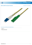
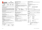
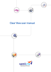
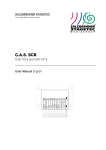
BroadLighter-T Bench Series Broadband SLD Light Sources Quick Start Guide for Models: BroadLighter T-840 BroadLighter T-860 BroadLighter T-870 Version 1.1 Version date: April 12, 2011 Superlum, Unit 1F, Eastlink Business Park, Carrigtwohill, Co. Cork, Ireland. Phone: +353 21 4533666, Fax: +353 21 4533026, E-mail: [email protected]. www.superlumdiodes.com BroadLighter-T Series Quick Start Guide 1. In This Document This guide has been designed to provide everything you will need to know about getting started with your broadband SLD light source. It is the purpose of this document to give you minimum information covering only the process of installation and the process of operation of the instrument under local control rather than the most comprehensive information concerning all aspects of the instrument operation and its design. Unlike the sections in the User Manual, some of the sections of this guide that have the similar headings have been simplified and re-arranged; the others, with different headings, have partly absorbed the necessary information from different chapters of the User Manual. If the information in this guide is insufficient for you, please read the full description of the instrument in the User Manual. Refer to the User Manual whenever you have a question the answer to which is not given in this document. If you have a particular (specific) question about the BroadLighter the answer to which you cannot find in our documents, do not hesitate to personally call us, or email the question using the following link: [email protected] Before starting to work with the instrument, you must pay close attention to the following important information: If your BroadLighter is assigned to Class 1 laser products (see the yellow label on the front panel of the device above the OUTPUT APERTURE), the information in this guide will be quite enough for ensuring the safe operation—any risk of being injured by excessive optical radiation from the instrument's output is excluded. But extra care must be taken if the Class of your BroadLighter is higher than Class 1. In this case, we strictly recommend you to read section "Laser Safety Information" in the User Manual before getting started with the instrument—the optical output radiation of the BroadLighter of that Class, under certain conditions, may be dangerous for the human eye. The information covered by this document is divided into the following sections: In This Document, on page 2 Before You Begin, on page 3 Power ON Instructions, on page 3 Features and Functions, on page 5 Getting Started, on page 7 Power OFF Instructions, on page 9 -2- BroadLighter-T Series Quick Start Guide 2. Before You Begin Find a suitable place to put the package with your BroadLighter before you start opening it. Ensure that the location you choose is rigid enough and wide enough to accommodate the package with the instrument. To unpack the instrument, follow the directions below: 1. Cut the adhesive tapes over the top of the carton exterior with a sharp knife and open the top flap. 2. Remove the cushioning material around the instrument. 3. Lift the instrument and set it aside. 4. Lift the accessories and set them aside. After opening the package, check that you have received the following items with your instrument: One AC power cord One optical patchcable Two keys for the instrument's master control One monophonic short-circuited connector One User Manual One Quick Start Guide Connectivity software on CD-ROM One RS-232 null-modem cable Acceptance Test Report If there is any item missing, please contact Superlum on this issue. 3. Power ON Instructions Before connecting the BroadLighter to your local power source, pay close attention to the warnings and cautions which follow. You should bear these warnings and cautions in mind whenever you connect or re-connect the BroadLighter to your power source. -3- BroadLighter-T Series Quick Start Guide WARNING Before the BroadLighter is switched on, all protective earth terminals, extension cords, and autotransformers should be connected to a protective earth-grounded receptacle. Any interruptions of the protective grounding conductor or disconnections of the protective earth terminal can make the instrument dangerous. It is strictly prohibited to perform an intentional interruption of the protective grounding conductor. For continued protection against fire hazard, replace the line fuse only with a fuse of the same rating. DO NOT use repaired fuses or short-circuited fuse holders. CAUTION Before the BroadLighter is switched on, make sure that the instrument is set to the same line voltage as the power source being used, and a correctly rated line fuse is installed. DO NOT use this equipment with AC power source which is different from that specified on the rear-panel label of the instrument. Failure to obey this rule may cause permanent damage to the instrument. Power ON instructions are as follows: 1. Place the BroadLighter on a flat surface (e.g. on a table or in a rack) close to your measuring equipment in a location with sufficient ventilation. Make sure that no obstructions are provided for ventilation openings of the instrument and the optical patchcable can be easily attached to the instrument without strain. 2. Check that the POWER pushbutton is set to OFF position. If it is not in OFF position, release the pushbutton by pressing it. 3. Connect AC power cord to the rear-panel power receptacle. Use the power cord supplied with instrument. -4- BroadLighter-T Series Quick Start Guide 4. Insert the key coming with the instrument into the MASTER KEY lock and leave it in position "O". 5. Plug in the instrument and press the POWER pushbutton. (The pushbutton LED lights up blue.) 6. The BroadLighter is now ready for use. 4. Features and Functions To feel at easy with the instrument, familiarize yourself with its front-panel and rearpanel controls, connectors, and indicators shown in the figures which follow. Explanations for each feature are organized numerically in the order as they are indexed in the corresponding figures. 2 3 4 5 6 7 8 9 10 11 3x1 Broadband SLD Light Source MASTER KEY SUPERLUM CONTROL REMOTE OPTICAL OUTPUT O Service SLDs I SLD1 Local SLD2 POWER REMOTE INTERLOCK SLD3 Output Aperture FC-APC BroadLighter T840 1 14 13 12 Fig. 1. Front-Panel Features 1—POWER. By pressing this pushbutton, the operator can turn the instrument on or off. When the pushbutton is in the depressed position, the LED indicator on the pushbutton lights blue, thereby indicating that the BroadLighter is enabled. 2—MASTER KEY (Laser Safety Measure). This is a key-operated master control used as a laser safety measure specified in IEC 60825-1 (Edition 2.0 2007-03). Turning the key in position "I" allows the operator to get access to SLD emission activation. With the key in position "O", the access is denied and the output emission of SLDs cannot be enabled. -5- BroadLighter-T Series Quick Start Guide 3—REMOTE. This LED illuminates green when the instrument is controlled remotely by using a PC. When the instrument is set for the local operation, the LED goes blank. 4—LOCAL. When the BroadLighter is under remote control, pressing this key causes the instrument to return to the local operation. 5,6,7—SERVICE. If the instrument lights these LEDs, the output power degradation of the SLDs has reached the maximum acceptable value and the instrument needs servicing. 8—SLDs. This is used to enable/disable all the SLDs (SLD1, SLD2, and SLD3) simultaneously. 9—SLD1. This is used to enable/disable the SLD1 emission. When the emission is activated, the pushbutton LED illuminates green. 10—SLD2. This is used to enable/disable the SLD2 emission. When the emission is activated, the pushbutton LED illuminates green. 11—SLD3. This is used to enable/disable the SLD3 emission. When the emission is activated, the pushbutton LED illuminates green. 12—PROTECTIVE CAP. This is used to protect the optical output (FC/APC adapter) from dust and dirty. Always recap the optical output, when the instrument is not in use and has no any patchcable attached. 13—OUTPUT APERTURE. This socket is an optical output of the instrument. The patchcable supplied with the instrument is connected here. 14—REMOTE INTERLOCK (Laser Safety Measure). This LED is used to inform the operator that the terminals of the remote interlock connector are opencircuited. When this happens, the LED illuminates red. -6- BroadLighter-T Series Quick Start Guide 1 2 RS-232 REMOTE INTERLOCK TM SUPERLUM www.superlumdiodes.com Broadband SLD Light Source P/N: T-840-XX SERIAL No: ##### RoHS COMPLIANT 2002/95/EC AC 215-230V; 50-60Hz FUSE: 2A FUSE 5 4 3 Fig. 2. Rear-Panel Features 1—RS-232 CONNECTOR. This is used to connect the BroadLighter to a PC for remote control. 2—REMOTE INTERLOCK (Laser Safety Measure). This is an audio monophonic jack which is used to connect the instrument to your local external controls for laser safety. 3—AC POWER INPUT RECEPTACLE. It accepts a 3-conductor power cord used to connect the instrument to your local AC power line. 4—AC LINE FUSE HOLDER. This is used to hold the line fuse. 5—GROUNDING TERMINAL. This is used to ground the instrument cabinet. This terminal accepts a male-banana-plug connector. 5. Getting Started To get started with your BroadLighter, carry out the following steps in the following order: 1. Connect the BroadLighter to your local external controls for laser safety. Use the REMOTE INTERLOCK jack on the rear panel of the instrument for this connection. If you do not have the external controls for laser safety in your local area, use the short-circuited connector supplied with instrument. 2. Connect one side of the optical patchcable supplied with the BroadLighter to the front-panel OPTICAL APERTURE; the other, to your measuring equipment (e.g. an optical power meter). To obtain low insertion optical losses -7- BroadLighter-T Series Quick Start Guide in the instrument-to-patchcable connection, always follow the instructions on the label affixed to the patchcable. 3. Press the POWER pushbutton to turn the instrument on. The pushbutton LED lights up blue. The TEC controllers of the both SLDs are activated automatically at power-on. Note that these controllers remain always activate until the instrument is turned off. 4. Turn the MASTER KEY control clockwise to position "I". Once the key has been turned, the instrument runs an internal test to verify whether the remote interlock connection is made or not. If the test passes, you are able to activate the optical output of the instrument (move on to step 6 to do this). If the test fails, the instrument starts to alarm continuously. In this case, the REMOTE INTERLOCK LED will steady red and a piezoelectric transducer built into the instrument will produce a continuous audible sound. Triggering the alarm warns of the fact that the remote interlock connection is open-circuited. Note that after triggering the alarm, the instrument ignores any your attempt to activate the output emission until the alarm is reset. To reset the alarm, turn the key to the OFF position. After that, check the remote interlock connection to be sure it is made correctly. Then turn the key to the ON position again. 5. Enable the optical output power by pressing the SLD1 pushbutton. When the pushbutton is pressed, a 3-sec activation delay runs. During the delay, the LED on the pressed pushbutton begins blinking, and the piezoelectric transducer produces a beep signal. When the delay is completed, the pushbutton LED switches to steady green light and the audible signal is automatically cut off; the output emission appears at the optical output of the instrument. 6. Enable SLD2 by pressing the SLD2 pushbutton, and then SLD3 by pressing the SLD3 pushbutton. 7. Disable the SLDs by pressing the same pushbuttons in the reverse order. 8. Enable all three SLDs simultaneously by pressing the SLDs pushbuttuon. Note that to enable all the SLDs simultaneously with the SLDs pushbutton, you need to have ALL three SLDs initially deactivated. 9. Verify the output power of the BroadLighter to be certain the current reading of your power meter corresponds to the value stated in the acceptance test report. -8- BroadLighter-T Series Quick Start Guide CAUTION 1. To keep the end faces of the optical patchable clean and protected, it is strictly recommended to avoid unnecessary disconnections of the patchcable from the BroadLighter and your measuring equipment. 2. NEVER connect optical connectors different from those specified for your BroadLighter, because they are not intended for the use with the instrument and can seriously damage its optical output. NOTE 1. With no connection between your laser safety controls and the instrument, it will ignore any your attempt to activate the output power as described in step 5. If you do not have such controls in your area, install the short-circuited connector supplied with instrument. 2. Once the BroadLighter is turned on, the optical output power of the instrument can slightly drift in time. For achieving greater stability of the output power, a 10-minute warm-up period is highly recommended. 3. To meet personal safety requirements, the optical output of the BroadLighter remains inactive until the 3-sec activation delay completes. 4. You can enable all three SLDs simultaneously by pressing the SLDs pushbutton. 6. Power OFF Instructions To turn off the instrument, proceed as follows: 1. If the optical output of the instrument is active, press the necessary pushbuttons (the SLD1/SLD2/SLD3/SLDs) to disable the output. 2. Turn the MASTER KEY control counterclockwise to position "O". 3. Press the POWER pushbutton. The LED on the pushbutton will go blank. -9- BroadLighter-T Series Quick Start Guide NOTE 1. Always disable the optical output before turning the instrument off. 2. If all three SLDs are active, you can disable them either (1) simultaneously by pressing the SLDs pushbutton, or (2) one after another by pressing the SLD1/SLD2/SLD3 pushbuttons in the desired order. 3. To disable the SLDs simultaneously with the SLDs pushbutton, it is necessarily needed to have ALL three SLDs initially activated. -10-