1
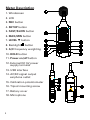
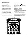
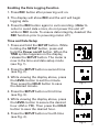
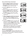
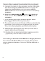
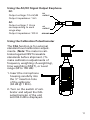
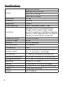
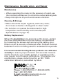
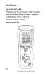
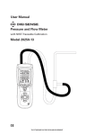
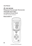
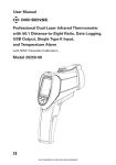
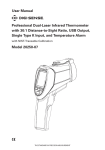
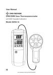
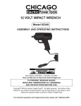
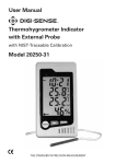
User Manual Data Logging Sound Level Meter with NIST-Traceable Calibration Model 20250-29 THE STANDARD IN PRECISION MEASUREMENT Introduction The Digi-Sense Data Logging Sound Level Meter (Model 20250-29) measures sound decibel levels for noise certification and reduction applications. The meter conforms to IEC61672-1 Class 2 standard. Advanced features include data Hold, Max/Min readings, low/medium/ high ranges, over and under range, and A and C weighting. The unit offers Fast/Slow response, analog AD/DC outputs, USB connectivity, data logging software, backlight display, and automatic power-off. The instrument is fully tested and calibrated to NIST-traceable standards. Careful use of this meter will provide years of reliable service. Unpacking Check individual parts against the list of items below. If anything is missing or damaged, please contact your instrument supplier immediately. 1. Meter 2. Windscreen 3. Earphone plug, 3.5 mm 4. Screwdriver 5. Three AAA batteries 6. USB cable 7. Software 8. User manual 9. NIST-traceable calibration report with data 2 Key Features • Wide measurement ranges of 30 to 130 dB • Precision accuracy of ±1.4 dB • Meets IEC61672-1 Class 2 standard • User selectable low/medium/high, and auto range measurement levels • A and C frequency weighting • Fast and slow time weighting • Memory of 32,700 readings • Max/Min and Hold functions • Over- and under-range indicator • AC/DC analog outputs • Data logging software with graphical display • Download data via USB connectivity • Large backlit LCD for easy reading • Low-battery indicator • Auto power-off after fifteen minutes of nonuse to conserve battery power 3 Meter Description 1. Windscreen 2. LCD 3. REC button 4. SETUP button 5. FAST/SLOW button 6. MAX/MIN button 7. LEVEL button 8. Backlight button 9. A/C frequency weighting 10. HOLD button 11. Power on/off button 12. External DC 5V power supply terminal 13. USB interface 14. AC/DC signal output earphone outlet 15. Calibration potentiometer 16. Tripod mounting screw 17. Battery cover 18. Microphone 4 Display Layout 1. Under-range icon 10. Auto power-off 2. Over-range icon 11. Low-battery 3. Maximum hold icon 12. Recording icon 4. Minimum hold icon 13. Memory full icon 5. Fast response icon 14. A-Weighting icon (response to human sense) 6. Slow response icon icon indication 7. Selected level range 15. C-Weighting icon (response to machinery) 8. Date and time symbols 16. Auto level range selection 9. Reading of sound level 17. Data Hold function icon 4 5 1 2 3 6 7 8 9 10 16 11 17 12 13 14 15 5 Setup and Operation 1. Remove the battery cover on the back and put in three AAA batteries. Replace the battery cover. 2. See Data Zero Function below to set before powering unit on. 3. Press the Power on/off button to turn the meter on. 4. Press the LEVEL button to select your desired low/ medium/high or auto level. (Note: With selected range, ensure that the UNDER or OVER icon is not displayed, which indicates you are out of range.) 5. Select dBA for general noise sound level or dBC for measuring sound level of acoustic material. 6. Select FAST for instant sound and SLOW for average sound levels. 7. Hold the unit in hand or fix-mount it on a tripod and measure sound level at a distance of 3.3 to 4.9 feet (1 to 1.5 meters). Data Zero Function 1. Before powering on, press and hold the REC button. 2. While holding the REC button down, press and hold the Power on/off button until the display reads CLR. This indicates that the data in memory has been deleted. 6 Enabling the Data Logging Function 1. Press REC button after powering unit on. 2. The display will show REC and the unit will begin logging data. 3. Press the REC button again to exit recording. (Note: In order to avoid data errors, do not power the unit off while in REC mode. To ensure data integrity, deselect the REC function prior to powering meter off.) Time and Date Setup 1. Press and hold the SETUP button. While holding the SETUP button, press and hold the Power on/off button. When the TIME symbol appears on the display, release the SETUP button. The meter is now in the time and date setup mode (see Fig. 1). Fig. 1 2. Press the SETUP button a second time (see Fig. 2). 3. While viewing the display above, press the LEVEL button to set the minute. Then press the HOLD button to save the desired minute. Fig. 2 4. Press the SETUP button a third time (see Fig. 3). 5. While viewing the display above, press the LEVEL button to secure the desired hour (AM or PM). Then press the HOLD button to save the desired hour. Fig. 3 6. Press the SETUP button a fourth time (see Fig. 4). Fig. 4 7 Time and Date Setup (Continued) 7. While viewing the display (see Fig. 4), press the LEVEL button to choose the desired day of the month. Then press the HOLD button to save this day. 8. Press the SETUP button a fifth time (see Fig. 5). 9. While viewing the display (see Fig. 5), press the LEVEL button to select the desired month of the year. Then press the HOLD button to save this month. Fig. 4 Fig. 5 10. P ress the SETUP button a sixth time (see Fig. 6). 11. While viewing the display (see Fig. 6), press the LEVEL button for the desired year. Then press the HOLD button to save the year. This completes the setup process. 12. Press the SETUP button a seventh time (see Fig. 7). This is the time/date reset function. Press the HOLD button to save. The time and date will then return to the original factory time and date setup. Fig. 6 Fig. 7 (Note: When the batteries fail or are replaced, you may have to reprogram the time/date. Simply follow steps #1 through #11 above.) Selecting Time Weighting Press the FAST/SLOW button to select fast or slow sampling times. FAST = sampling measurement of one time per 125 mS. SLOW = sampling measurement of one time per second. 8 Viewing the Min and Max Readings 1. Press the MAX/MIN button once and MAX icon will appear on the display. In this mode, the maximum sound level will be captured and held until a higher sound level is captured. 2. Press the MAX/MIN button again and the MIN icon will appear on the display. In this mode, the minimum sound level will be captured and held until a lower sound level is captured. 3. Press the button one more time to exit the MAX/MIN function. Selecting Level Range Press the LEVEL button to select low/medium/high, or auto decibel measuring range. The selected range will appear in the upper left and upper right of the display. LCD Backlight Press the Backlight display backlight. button to activate or deactivate the Selecting Frequency Weighting Press A/C button to select A or C weighting. Either the dBA (A-weighting) or dBC (C-weighting) icon will be displayed. Freezing the Reading Press HOLD button to freeze the reading in the display. 9 Connecting the USB Cable 1. Turn on the meter and connect the USB cable to the USB port located on the side of the meter. 2. Connect the other end of the USB cable to the computer. 3. Choose the software COM3 (COM). 4. Press the SETUP button. The auto power-off icon will disappear from the display, indicating the disabling of the auto power-off function and the successful transmission of USB data. The USB signal output is a 9600 bps serial interface. Installing Software 1. Insert the CD into the PC. 2. Run SETUP.EXE on the CD. Follow the installation wizard to complete the installation. 3. Upon successful installation, the Sound Level Meter software icon shortcut will be automatically placed on the PC desktop. 4. If the USB driver needs to be updated (or if you receive the driver error message), go to the folder with the driver on the CD and double click the file CP210xVCPInstaller.exe to update the driver. (With disk in the computer, D drive/USB Driver folder). Activating Real-Time Data Logging 1. Once the driver software is installed, start the application software by selecting the Auto (A) function from the Com Port dropdown menu at the top of the menu bar. Then connect the meter to the computer via the USB cable. 10 2. M ake sure the auto power-off icon does not appear in the instrument display by pressing the SETUP button. When this symbol is not displayed, the meter is transmitting data to the computer. 3. Select the Real Time (R) from the top menu bar; select Setup (U) from the dropdown menu. 4. In the Setup menu screen, select the preferred Real Time Sampling Rate then press Start. 5. You may stop the data logging function by selecting the Stop symbol located at the top of the menu bar. Simply select the Excel document symbol at the top of the menu bar to instantly download your current data session to the preformatted Excel document. 6. T o set A and B cursors, simply double click on the graphical display of data taken and the cursor information will automatically populate within the cursor designated box. Remote Data Logging/ Downloading Data 1. C lear all data from the instrument. See Data Zero Function instructions on page 6. 2. Set the unit to your desired sampling speed, frequency weighting, and level settings (see pages 8–9). 3. Press REC button to begin recording data. The REC icon will be displayed in the lower left of the display. 4. When data recording is complete, push the REC button again to stop the data logging function. The REC icon should disappear from the lower left of the display. 11 Remote Data Logging/ Downloading Data (continued) 5. Connect the meter to the computer via the USB cable. See Connecting the USB Cable section on page 10. Select the Sound Meter icon from your desktop. (Note: Software must already have been successfully installed.) 6. Make sure auto power-off icon is not displayed in the screen. Press SETUP button to deactivate if necessary. 7. In the sound level meter software screen, select Data logger (D) from the top menu bar. 8. The summarized record of data will then automatically download to the screen and be tagged with ID, Date/ Time, Unit, Sampling Rate and Nums information. 9. Select Export to Excel (E) from the top menu bar to export data to Excel if desired. 10. D ouble click on summarized data logging record to graphically view the data on the screen. Connecting to the External 5 VDC Power Supply Terminal To connect with the 5 VDC power supply, the aperture size is: external diameter = 3.5 mm, internal diameter = 1.35 mm. 12 Using the AC/DC Signal Output Earphone DC: Output voltage: 10 mV/dB Output impedance: 1 kΩ DC OUTPUT AC: Output voltage: 1 Vrms corresponding to each range step Output impedance: 100 Ω AC OUTPUT GROUND Using the Calibration Potentiometer The CAL function is for external standard level calibration adjustments. (Note: The meter is calibrated against NIST-traceable standards before shipment.) To make calibration adjustments of frequency weighting (A-weighting), time weighting (FAST), or Level range (50 to 100 dB): 1. Insert the microphone housing carefully into the 1⁄2" insertion hole of the calibrator (94 dB @ 1 KHz). 2. Turn on the switch of calibrator and adjust the CAL potentiometer of the unit until 94.0 dB is displayed. 13 Specifications Range Resolution Accuracy Weighting Time weighting Functions Max/Min, Hold, Low/medium/high ranges, Over-range, Under-range, A and C weighting, Fast/Slow response, Memory, Data logging software, Backlit display, and Automatic power-off Frequency range Dynamic range Memory Display update Connectivity 31.5 Hz to 8 kHz 50 dB 32,700 readings 2 times/sec USB Analog output AC/DC outputs from earphone outlet; AC = 1 Vrms, DC = 10 mV/dB Microphone Operating conditions Storage conditions Approvals Display Dimensions (L x W x H) Power Weight 14 Low: 30 to 80 dB Medium: 50 to 100 dB High: 80 to 130 dB Auto: 30 to 130 dB 0.1 dB ±1.4 dB A and C Fast = 125 m/sec, Slow = 1 sec 1⁄2 " electret condenser microphone 32 to 104°F (0 to 40°C); 10 to 90% RH 14 to 140°F (–10 to 60°C); 10 to 75% RH IEC61672 -1 Class 2 4-digit backlit LCD with bar graph 91⁄4" x 27 ⁄16 " x 11⁄16 " (235 x 61 x 27 mm) Three AAA batteries 9.8 oz (280 g) Maintenance, Recalibration, and Repair Maintenance • When operating the meter in the presence of wind, use the included windscreen to eliminate undesirable signals. • Keep microphone dry and avoid severe vibration. Cleaning & Storage • Meter should be wiped regularly with a dry cloth; do not use solvents or detergents to clean meter. • Do not store or operate the instrument in high temperature and humidity environments (see Specifications on page 14). Battery Replacement When the low-battery icon appears on the screen, replace the three AAA batteries in the rear battery compartment by loosening the screws and removing the battery door. Ensure cover is securely refastened when finished. Remove batteries if unit is not being used for extended time periods. It is recommended that Digi-Sense products are calibrated annually to ensure proper function and accurate measurements; however, your quality system or regulatory body may require more frequent calibrations. To schedule your recalibration, please contact InnoCal, an ISO 17025 calibration laboratory accredited by A2LA. Phone: 1-866-INNOCAL (1-866-466-6225) Fax: 1-847-327-2993 E-mail: [email protected] Web: InnoCalSolutions.com 15 For Product and Ordering Information, Contact: Toll-Free: 1-800-323-4340 Phone: 1-847-549-7600 Fax: 1-847-247-2929 ColeParmer.com/Digi-Sense 1065DGMAN_20250-29 Rev.1 Toll-Free: 1-800-358-5525 Phone: 1-847-327-2000 Fax: 1-847-327-2700 Davis.com/Digi-Sense Manual Part No. 00100-60