1
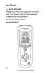
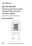
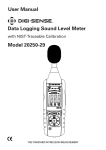
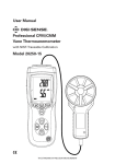
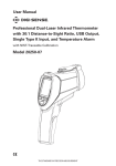
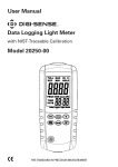
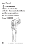
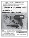
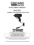
User Manual Pressure and Flow Meter with NIST-Traceable Calibration Model 20250-13 MAX MIN P/V/F THE STANDARD IN PRECISION MEASUREMENT 2 Introduction The Digi-Sense Pressure and Flow Meter (Model 20250-13) measures differential and static pressure, and calculates air velocity and airflow. This heavy-duty meter ensures proper airflow balance and monitors air pressure across key HVAC components—promoting good indoor air quality and a comfortable environment. Advanced features include data save/recall, Hold function, Max/Min/Avg readings, and automatic power-off. The instrument is fully tested and calibrated to NIST-traceable standards. Careful use of this meter will provide years of reliable service. Unpacking Check individual parts against the list of items below. If anything is missing or damaged, please contact your instrument supplier immediately. 1. Meter 2. White and black tubing 3. Pitot tube 4. USB cable 5. Software 6. Carrying case 7. One 9 V battery 8. User manual 9. NIST-traceable calibration report with data Key Features • Large backlit LCD displays pressure, air velocity, or airflow plus environmental temperature simultaneously • Relative time clock on Max/Min/Avg provides a time reference for major events • USB interface; USB to HART bridge controller • Save and recall of 99 sample readings per parameter • Automatic power-off (sleep) mode to conserve battery life 3 1 Meter Description 1. Pitot tube 4 2. Input port (+); white tubing 3 3. Reference port (–); black tubing 5 2 4. Temperature sensor 5. LCD 6. Press Power on/off button to turn the meter on and off. 7. Press MAX/MIN button to step through the maximum, minimum, and average readings. To exit the Max/Min/Avg mode, press and hold MAX/MIN button for two seconds to resume normal operation. 14 12 13 10 9 11 7 MAX MIN P/V/F 8 6 8. Press P/V/F button to toggle between differential pressure, air velocity, and airflow measurements. For air velocity, press P/V/F button again to show the height and length of a rectangular or the diameter circular duct. 9. Press HOLD/ZERO button to freeze or unfreeze the displayed readings. Press and hold HOLD/ZERO button for two seconds to zero out the display. 10. Press SAVE/CLEAR button to store sample data. Or press SAVE/CLEAR button to clear sample data in Recall mode. 11. Press Setup/ Backlight button to turn the backlight on and off. Press and hold Setup/Backlight button for three seconds to enter or exit the Setup mode. (See "Changing Setup Options.") 12. Press /Unit button to change the temperature units (°C or °F) on the secondary display. a. In the Setup mode, use the /Unit button to scroll to the Setup option you want to change or to increase the displayed setting. b. In the Recall mode, use the /Unit button to select the desired sample number. 13. Press Unit/ button to change the units of measure on the primary display. a. In the Setup mode, use the Unit/ button to scroll to the Setup option you want to change or to decrease the displayed setting. b. In the Recall mode, use the Unit/ button to select the desired sample number. 14. Use Avg/Rec button for two functions: a. Press and hold Avg/Rec button for two seconds to enter the Recall mode to view the stored sample data. While in Recall mode, press Avg/Rec button to calculate the average of all sample data. b. In Setup mode, press Avg/Rec button to enter a Setup option. Press Avg/Rec button again to store the new setting into memory. 4 Display Functions 20 1 19 2 18 3 4 5 17 6 16 15 7 14 13 8 9 10 11 12 1. Hour:min and min:sec icons 2. Pressure, velocity, flow and temperature modes 3. Primary display 4. Units of air velocity (knots, MPH, ft/min, m/s, km/h) 5. Units of pressure (psi, mbar, in. H2O, mm H2O, Pa) 6. Indication of meter communicating to PC 7. Auto power-off mode icon 8. Duct shape choices 9. Low-battery indicator 10. Data HOLD icon 11. Units of H, W, or D (in., cm) 12. SETUP mode icon 13. Clear icon: indicates that a stored sample (or all samples) is about to be deleted from memory 14. Number of samples stored in memory or a specific sample location in Recall mode 15. MEM: indicates that sample memory is being accessed 16. REC, MAX, MIN and AVG icons 17. Temperature units of primary display (°C, °F) 18. Units of air flow (CFM, CMM) 19. Temperature units of secondary display (°C, °F) 20. Secondary display (time elapsed or temperature) 5 Changing Setup Options Use the Setup mode to choose duct shape and dimensions, set duct parameters, set which measurement parameters are displayed, change sleep mode, and clear memory. The meter stores the new settings into its memory. Option Duct dimensional units Menu item Unit Settings Set duct units (in. or cm) Duct shape and parameters Duct shape Set area of measuring airflow Measurement parameters displayed tYPE 1, 2, or 3 Auto power-off mode SLEEP Clear memory ALL On (sleep mode on) or Off (sleep mode off) Yes or No for all parameters or for each parameter Entering or Exiting Setup Mode When the meter is in Setup mode, the display shows the SETUP icon. Press and hold Setup button for two seconds to enter or exit the Setup mode. Changing a Setup Option 1. Press /Unit or Unit/ button scroll to the Setup option you want to change. 2. Press Avg/Rec button to indicate that you want to change this setting. 3. Press /Unit or Unit/ button until the setting you want to use appears on the display. 4. Press Avg/Rec button to store the new setting into memory. Note: Setup mode is disabled in the Max/Min/Avg mode. 6 Setting the Duct Dimensional Units 1. While the meter is in Setup mode, press /Unit or Unit/ button to scroll to the duct dimension units setup option (Fig. 1). Fig. 1 Fig. 2 2. Press Avg/Rec button to access the units; “cm” will appear on the display (Fig. 2). 3. Press /Unit or Unit/ button to toggle between “cm” and “in.” units. 4. Press Avg/Rec button to store the new setting into memory. Choose a Duct Shape 1. While the meter is in Setup mode, mode, press /Unit or Unit/ button to scroll to the Duct Shape setup option (Fig. 3). Fig. 3 Fig. 4 2. Press Avg/Rec button to access the shapes; the “ n ” (rectangle) appears on the display. 3. Press /Unit or Unit/ button to toggle between “ n ” (rectangle) and “ l ” (circular) shapes (Fig. 4). 4. Press Avg/Rec button to store the new setting into memory and to enter the Parameters setup option. 7 Changing Setup Options (continued) Setting Duct Parameters 1. If duct shape is rectangular, the width of duct numbers and “W=” will appear on the display (Fig. 5). 2. Press /Unit or Unit/ button to move the position of the decimal point. 3. Press SAVE/CLEAR button to select the station of flashing digit. 4. Use the /Unit or Unit/ buttons to change the flashing digit from 0 to 9. 5. Press SAVE/CLEAR button to continue to change the next flashing digit. Fig. 5 6. Press Avg/Rec button to save the new settings into memory. The height of duct numbers and “H=” will now appear on the display (Fig. 6). 7. Press /Unit or Unit/ button to move the position of the decimal point. 8. Press SAVE/CLEAR button to select the station of flashing digit. 9. U se the /Unit or Unit/ buttons to change the flashing digit from 0 to 9. Fig. 6 10. Press SAVE/CLEAR button to continue to change the next flashing digit. 11. Press Avg/Rec button to save the new settings for W and H into memory. 12. If duct shape is circular, the diameter of duct numbers and “D=” will be shown on the display. 13. Press /Unit or Unit/ button to move the position of the decimal point. 14. Press SAVE/CLEAR button to select the station of flashing digit. 15. Use the /Unit or Unit/ buttons to change the flashing digit from 0 to 9. 16. Press SAVE/CLEAR button to continue to change the next flashing digit. 17. Press Avg/Rec button to save the new settings into memory. 8 Clearing Memory Data 1. While in Setup mode, press /Unit or Unit/ button to scroll to the Clear Memory setup option (Fig. 7). 2. Press Avg/Rec button to access the choices (Fig. 8). 3. Press SAVE/CLEAR button to toggle between four selections: PRESS VEL FLOW = all pressure, velocity and flow sample data PRESS = only pressure sample data VEL = only velocity sample data FLOW = only airflow sample data 4. Use /Unit or Unit/ buttons to toggle between “Yes” (clear data) or “No” (do not clear data). Press Avg/Rec button to enter new setting. Fig. 7 Fig. 8 9 Changing Setup Options (continued) Selecting which Measurement Parameters are Displayed 1. While in Setup mode, press /Unit or Unit/ button to scroll to the Measurement Type setup option (Fig. 9). 2. Press the Avg/Rec button to access the three types. Use the /Unit or Unit/ button to toggle between the three choices: 1 = Display pressure and air velocity value 2 = Display air velocity and airflow value 3 = Display pressure, air velocity, and airflow value (Fig. 10) Fig. 9 3. Press Avg/Rec button to save the new setting into memory. Note: When in measuring mode, you will still need to use the P/V/F button to toggle between displaying your chosen parameters. Fig. 10 Auto Power-Off (APO)/Sleep Mode The meter’s default mode is to automatically shut off after 20 minutes of non-use. To disable the auto power-off mode, enter the Setup mode. 1. While in Setup mode, press /Unit or Unit/ button to scroll to the SLEEP setup option screen (Fig. 11). 2. Press Avg/Rec button to display “On.” 3. Use the /Unit or Unit/ button to toggle between “On” (sleep mode on) or “Off” (sleep mode off) (Fig. 12). Fig.11 4. Press Avg/Rec button to store the new setting into memory. Note: meter defaults back to "On" once meter is powered off. Fig. 12 10 Setup and Operation Measuring Pressure The gauge/differential pressure value is shown on the primary display. 1. Press P/V/F button to enter the pressure measuring mode; PRESS icon will appear. 2. Use /Unit or Unit/ button to toggle between five units of measurement (psi, mbar, in. H2O, mm H2O, or Pa). 3. Connect a single hose to the "Input (+)" port, leaving the "Ref (-)" port unconnected (Fig. 13). inPut (+) MAX MIN P/V/F Fig. 13 4. With the tubing open to ambient conditions, press and hold the HOLD/ZERO button for two seconds to zero out the display. 5. Place the input hose in a different zone than the meter. 6. The meter displays the differential pressure of the input zone with respect to the reference zone. For instance, a positive reading means that the input zone is positively pressured with respect to the meter location or its reference zone. Note: The Hold, Save, Max/Min/Avg, Zero, and Setup modes can be used when measuring pressure, air velocity and airflow. 11 Setup and Operation (continued) Measuring Air Velocity The meter uses standard ambient conditions (temperature @ 70°F/21.1°C, barometric pressure @ 14.7 psi/1013 mbar) to approximate actual air velocity and airflow. Air velocity value is shown on primary display. 1. Press P/V/F button to enter the air velocity measuring mode; VEL icon will appear. 2. Use Unit/ button to toggle between five units of measurement (knots, MPH, ft/min, m/s, or km/h). 3. C onnect the hoses to the pitot tube and to the meter. The “Input (+)” pressure port on the meter connects to the white hose from the total pressure connection of the pitot tube. The “Ref (-)” pressure port on the meter connects to the black hose from the static pressure connection of the pitot tube. 4. W ith the tubing open to ambient conditions, press and hold the HOLD/ZERO button for two seconds to zero out the display. inPut (-) inPut (+) FLOW MAX MIN P/V/F Fig. 14. Pitot Tube Connection 5. When taking a measurement, position the pitot tube tip against the airflow (Fig. 14) and ensure that the axis of the pitot tube is aligned with the duct within ±10°. If the measured velocity value measures negative and shows “Error” on the display, check to make sure that the hoses are attached to the correct ports on the meter and the pitot. Note: The Hold, Save, Max/Min/Avg, Zero, and Setup modes can be used when measuring pressure, air velocity and airflow. 12 Measuring Airflow The airflow value is shown on the primary display. 1. Press P/V/F button to enter the airflow measuring mode; FLOW icon will appear. 2. Use Unit/ button to toggle between two units of measurement (CFM or CMM). 3. Press P/V/F button to access the Duct Shape screen. The display shows the previously entered duct shape and size. If the duct you are now measuring is different than this stored version, follow directions on pages 6–8 to change the duct shape and parameters. Note: The Hold, Save, Max/Min/Avg, Zero, and Setup modes can be used when measuring pressure, air velocity and airflow. Displaying Temperature Ambient temperature is shown on the secondary display as a reference. Use the /Unit button to select your desired temperature unit (either °C or °F). Holding the Displayed Readings Press the HOLD/ZERO button to freeze the readings on the display. The screen will show the HOLD icon. Press HOLD/ZERO button again to exit this function. Viewing the Max, Min, and Avg Readings 1. Press the MAX/MIN button to step through the maximum (MAX), minimum (MIN), and average (AVG) readings. The elapsed time since entering the Max/Min/Avg mode, or the time at which the minimum or maximum reading occurred, appears on the secondary display. 2. Press the P/V/F button to step through the maximum, minimum, and average readings for the pressure, air velocity and airflow parameters. 3. Press and hold the MAX/MIN button for three seconds to exit the Max/Min/Avg mode and return to normal operation. 13 Setup and Operation (continued) Saving Measurement Samples The meter can save up to 99 samples in each of the three measuring parameters. Once the memory is full for a measuring parameter, “FU” will appear under the MEM icon and the meter will emit a short beep. You will not be able to save any additional samples until some or all saved data samples are deleted for that parameter. (See “Clearing Individual Data Samples from Memory” below.) 1. Press SAVE/CLEAR button to save the reading sample into memory. The meter will emit a short beep. The number of samples saved will be indicated under the MEM icon on lower right of screen (Fig. 15). Recalling Sample Data from Memory 1. P ress the P/V/F button to recall samples for a specific measuring mode. 2. P ress and hold the Avg/Rec button for two seconds to recall sample data. The REC icon will appear on the screen (Fig. 15). 3. T he sample number being displayed is indicated under the MEM icon. The last measurement saved will appear first. Use the /Unit and Unit/ buttons to view different sample readings. 4. P ress the Avg/Rec button again to view the average of all the saved sample data. The AVG icon will appear above the MEM icon. Fig. 15 5. P ress and hold the Avg/Rec button for two seconds to exit the Recall mode. Clearing Individual Data Samples from Memory 1. P ress the P/V/F button to recall saved samples for a specific measuring mode. 2. P ress and hold the Avg/Rec button for two seconds to recall sample data. The REC icon will appear on the screen (Fig. 15). 3. T he sample number being displayed is indicated under the MEM icon. The last measurement saved will appear first. Use the /Unit or Unit/ buttons to view a specific sample reading. 4. P ress the SAVE/CLEAR button to delete that individual sample from memory. Once you are back in measuring mode, you will notice that the number of saved samples is reduced. 5. P ress and hold the Avg/Rec button for two seconds to exit the Recall mode. Note: To clear all sample data for a specific measuring parameter or for all measuring parameters, refer to “Changing Setup Options, Clearing Memory Data” on page 9. 14 Recording/Data Logging Operation (Software) 1. F irst install software on PC following the setup wizard (see “Software Installation” below). Once software is successfully installed, the “Mano and Flow” software icon shortcut will be automatically placed on your PC desktop. 2. Connect the meter to your PC via the supplied USB cable. 3. Power the meter on. 4. Open the installed Multi Data Logger Software by double-clicking on the “Mano and Flow” icon on your PC desktop. 5. When opened, double-click on the meter image of the meter located in the left-hand white pane box. This will activate the image of the meter’s screen to illuminate. 6. On the menu bar, select the PC image icon (when mouse dragged over icon it is titled “Data logger Setting”). 7. In the Data Logger Setting menu, confirm time and select date format, sampling rate, memory full directions, auto power off status, and start method, then select “OK”. You must set these parameters before meter will record measurements. a. Note: Manual start method is controlled by user pressing REC button on instrument, automatic start method will activate recording via the software instantly once selected. 8. In manual record mode, press and hold the REC button on the meter for three seconds until the REC icon is displayed on the screen. This will indicate that recording function has been activated. Upon completion of desired data logging of measurements, press and hold the REC button for three seconds until the REC icon disappears from the meter display, indicating data logging has been deactivated. 9. To download the data to the PC, select the downward facing arrow in menu bar in the software window. The software screen will display the data being downloaded from the meter. Upon completion of downloading the data to the PC, the data results will be displayed graphically. 10. To save the measurement data to your PC, select the “Data List” tab to open the list of measurements recorded. Select “File” icon from the menu bar and save data to desired location on your PC. Note: Data will be saved in an Excel® format that will include all summary information as captured on the “Data Summary” tab. 11. To print recorded data, simply select the “print” icon on the menu bar. 15 Software Installation 1. Insert the CD into the PC. 2. Double click the set up.exe file to launch the software installation program. 3. Follow the installation wizard to complete the installation. 4. If the USB driver needs to be updated or driver error message is received, please go to the folder with driver on the CD and double-click the file CP210xVCPInstaller.exe to update the driver. 5. Upon successful installation of the software, the “Mano and Flow” software icon shortcut will be automatically placed on your PC desktop. 6. For additional information, click on “Help” at the top of the software menu bar for detailed instructions and examples of graphs and files. Error Codes An error message will appear on the display if the meter fails an internal diagnostic test. And it will freeze all the buttons. OL: Pressure or air velocity value is over the valid range. –OL: Pressure value is below the valid range. Error: Air velocity or airflow value is below the valid range. 16 Specifications Units Pressure psi mbar in. H2O mm H2O Pa Air Velocity m/s (meters per sec) ft/min (feet per min) km/h (kilometers per hr) MPH (miles per hr) Knots (nautical MPH) Airflow CFM (ft3/min) CMM (m3/min) Temperature °F °C Pressure repeatability Pressure linearity hysteresis Maximum pressure Display Response time Automatic power-off Operating conditions Storage conditions Weight Dimensions Power supply Range Resolution Accuracy 0 to 0.7252 0 to 50 0 to 20.07 0 to 509.8 0 to 5000 0.0001 0.01 0.01 0.1 1 ±0.3% full-scale 1.00 to 80.00 200 to 15,733 3.6 to 288.0 2.24 to 178.66 2.0 to 154.6 0.01 1 0.1 0.01 0.1 — — — — — 0 to 99.999 0 to 99.999 0.0001 to 100 0.001 to 100 — — 32 to 122 0 to 50 0.1 0.1 ±2.0 ±1.0 ±0.2% (max ±0.5% full-scale) ±0.29% full-scale 10 psi Backlit LCD 0.5 sec typical Unit shuts off automatically after 20 minutes to preserve battery life 32 to 122°F (0 to 50°C), 90% RH noncondensing 14 to 140°F (–10 to 60°C), 90% RH noncondensing 10.2 oz (290 g) 8" x 3" x 2" (20 × 7.5 × 5 cm) One 9 V battery 17 Maintenance, Recalibration, and Repair Cleaning and storage • The meter should be cleaned with a damp cloth and mild detergent when necessary. Do not use solvents or abrasives. • Store the meter in an area with moderate temperature and humidity (refer to the operating and storage conditions in the specifications chart earlier in this manual). Battery Replacement When the battery power falls low, the low-battery icon will appear on the screen. Replace the 9 V battery in the rear battery compartment by removing the cover. Ensure that the cover is securely refastened when finished. It is recommended that Digi-Sense products are calibrated annually to ensure proper function and accurate measurements; however, your quality system or regulatory body may require more frequent calibrations. To schedule your recalibration, please contact InnoCal, an ISO 17025 calibration laboratory accredited by A2LA. Phone: 1-866-INNOCAL (1-866-466-6225) Fax: 1-847-327-2993 E-mail: [email protected] Web: InnoCalSolutions.com 18 19 For Product and Ordering Information, Contact: Toll-Free: 1-800-323-4340 Phone: 1-847-549-7600 Fax: 1-847-247-2929 ColeParmer.com/Digi-Sense 1065DGMAN_20250-13 Rev.1 Toll-Free: 1-800-358-5525 Phone: 1-847-327-2000 Fax: 1-847-327-2700 Davis.com/Digi-Sense Manual Part No. 00100-52