1
SI-83 User Manual
SI-83
User Manual
SI-83 User Manual
Revision
Release Date
V1.0
2014/12/12
ii
iii
IBASE Technology Inc.
Copyright © 2013 IBASE Technology Inc. All Rights Reserved.
No part of this manual, including the products and software described in it, may be
reproduced, transmitted, transcribed, stored in a retrieval system, or translated into
any language in any form or by any means, except documentation kept by the
purchaser for backup purposes, without the express written permission of IBASE
Technology INC. (“IBASE ”).
Products and corporate names mentioned in this manual may or may not be
registered trademarks or copyrights of their respective companies, and are used for
identification purposes only. All trademarks are the property of their respective
owners.
Every effort has been made to ensure that the contents of this manual are correct and
up to date. However, the manufacturer makes no guarantee regarding the accuracy of
its contents, and reserves the right to make changes without prior notice.
Copyright © 2013 IBASE Technology Inc. All Rights Reserved.
SI-83 User Manual
Table of Contents
Setting up your system ................................................................................................ v
Care during use ........................................................................................................... vi
Acknowledgments ....................................................................................................... vi
CHAPTER 1 INTRODUCTION .................................................................................... 1
1.1 General Description ................................................................................................ 1
1.2 System Specifications ............................................................................................ 2
1.2.1 Hardware Specifications ..................................................................................... 2
1.2.2 Dimensions .......................................................................................................... 3
1.2.3 I/O View ................................................................................................................. 3
1.2.3 I/O View ................................................................................................................. 4
1.3 Exploded View of the SI-83 Assembly................................................................... 5
1.3.1 Parts Description ................................................................................................. 6
1.4 Packing List............................................................................................................. 7
1.4.1 Optional Items ...................................................................................................... 7
1.5 HARDWARE INSTALLATION .................................................................................. 8
1.5.1 Installing the Mounting Kit .................................................................................. 8
1.5.2 Installing the Optional Wireless Module ............................................................ 9
1.5.3 Installing mSATA ................................................................................................ 12
1.5.4 SI-83 Mounting Bracket Solution ...................................................................... 13
CHAPTER 2 MOTHERBOARD INTRODUCTION .........................................................14
2.1 Introduction ........................................................................................................... 14
IB983 Jumpers and Connectors ......................................................................... 16
2.2 Installations ........................................................................................................... 18
2.2.1 Installing the Memory ................................................................................... 18
2.3 Setting the Jumpers ............................................................................................. 19
2.4 Connectors on IB983 ............................................................................................ 21
CHAPTER 3 BIOS SETUP .........................................................................................26
3.1 BIOS Introduction ................................................................................................. 26
3.2 BIOS Setup ............................................................................................................ 26
CHAPTER 4 DRIVERS INSTALLATION .......................................................................46
4.1 Intel Chipset Software Installation Utility ............................................................ 46
4.2 VGA Drivers Installation ....................................................................................... 48
4.3 Realtek HD Audio Driver Installation ................................................................... 50
4.4 LAN Drivers Installation ....................................................................................... 52
4.5 Realtek LAN Controller Drivers Installation ....................................................... 55
4.6 Intel® Management Engine Interface .................................................................. 57
4.7 Intel® USB 3.0 Drivers .......................................................................................... 60
Appendix ...............................................................................................................63
A. I/O Port Address Map ............................................................................................. 63
B. Interrupt Request Lines (IRQ) ............................................................................... 64
C. Watchdog Timer Configuration ............................................................................. 65
iv
v
IBASE Technology Inc.
Safety Information
Your SI-83 is designed and tested to meet the latest standards of safety for
information technology equipment. However, to ensure your safety, it is important that
you read the following safety instructions
Setting up your system
Read and follow all instructions in the documentation before you operate your
system.
Do not use this product near water.
Set up the system on a stable surface. Do not secure the system on any unstable
plane.
Do not place this product on an unstable cart, stand, or table. The product may
fall, causing serious damage to the product.
Slots and openings on the chassis are for ventilation. Do not block or cover these
openings. Make sure you leave plenty of space around the system for ventilation.
Never insert objects of any kind into the ventilation openings.
This system should be operated from the type of power indicated on the marking
label. If you are not sure of the type of power available, consult your dealer or
local power company.
Use this product in environments with ambient temperatures between 0˚C and
45˚C.
If you use an extension cord, make sure that the total ampere rating of the
devices plugged into the extension cord does not exceed its ampere rating.
DO NOT LEAVE THIS EQUIPMENT IN AN ENVIRONMENT WHERE THE
STORAGE TEMPERATURE MAY GO BELOW -20° C (-4° F) OR ABOVE 80° C
(176° F). THIS COULD DAMAGE THE EQUIPMENT. THE EQUIPMENT
SHOULD BE IN A CONTROLLED ENVIRONMENT.
Copyright © 2013 IBASE Technology Inc. All Rights Reserved.
SI-83 User Manual
Care during use
Do not walk on the power cord or allow anything to rest on it.
Do not spill water or any other liquids on your system.
When the system is turned off, a small amount of electrical current still flows.
Always unplug all power, and network cables from the power outlets before
cleaning the system.
If you encounter the following technical problems with the product, unplug the
power cord and contact a qualified service technician or your retailer.
The power cord or plug is damaged.
Liquid has been spilled into the system.
The system does not function properly even if you follow the operating
instructions.
The system was dropped or the cabinet is damaged.
Lithium-Ion Battery Warning
CAUTION: Danger of explosion if battery is incorrectly replaced. Replace only with
the same or equivalent type recommended by the manufacturer. Dispose of used
batteries according to the manufacturer’s instructions.
NO DISASSEMBLY
The warranty does not apply to the products that have been disassembled by users
WARNING
HAZARDOUS MOVING PARTS
KEEP FINGERS AND OTHER BODY PARTS AWAY
vi
vii
IBASE Technology Inc.
Acknowledgments
AMI is a registered trademark of AMI Software International, Inc.
AMD and ATI are registered trademarks of AMD Corporation.
Microsoft Windows is a registered trademark of Microsoft Corporation.
FINTEK is a registered trademark of FINTEK Electronics Corporation.
REALTEK is a registered trademark of REALTEK Electronics Corporation.
All other product names or trademarks are properties of their respective
owners.
Copyright © 2013 IBASE Technology Inc. All Rights Reserved.
SI-83 User Manual
CHAPTER 1 INTRODUCTION
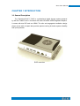
1.1 General Description
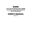
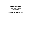
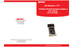
The “Signature Book™” SI-83 is a professional digital signage system powered
by 4th Gen. Intel® CoreTM i Processor with Intel® HD 4600 / 4400 Integrated Graphics.
It comes with dual DP and one HDMI. The slim and segregated ventilation design
player comes with a chassis that provides passive cooling for better system reliability
and quiet operation.
SI-83 overview
1
SI-83 User Manual
2
1.2 System Specifications
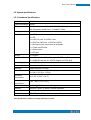
1.2.1 Hardware Specifications
Model Name
SI-83
System Mainboard
IB983
CPU
4th Generation Intel® Core™ i7-4700EQ 2.4GHz
4th Generation Intel® Core™ i5-4400E 2.7GHz
Memory
2x DDR3L-1600 MHz SO-DIMM, Max. 16GB (Non-ECC)
I/O Interface
1 x HDMI
2 x DP
2 x USB 3.0 ports, 2x USB 2.0 port
2 x RJ45 for GbE LAN, 1x RJ45 for RS232
1 x Microjack audio connectors for Audio/Mic
1 x Power on/off button
1 x Reset button
1 x DC jack
Storage
1 x mSATA
Expansion Slots
1 x mPCIe(x1) for WiFi + Bluetooth, 3G, GPS and TV tuner options
1 x UIM/SIM card slot (for 3G/LTE adapter in mPCIe slot)
Power Supply
+ 12V DC-in
Construction
Aluminum + SGCC
Mounting
Standard system bracket
Dimensions
175mm(W) x 116mm(D) x 32mm(H)
6.9”(W) x 4.6”(D) x 1.18”(H)
Operating
Temperature
Storage
Temperature
0°C~ 45°C (32°F~113°F)
-20° ~ 80°C (-4°F~176°F)
Relative Humidity
5~90% @ 45°C, (non-condensing)
Vibration
mSATA: 5 grms / 5~500Hz / random operation
RoHS
Available
Certification
CE, FCC, UL, CCC
‧This specification is subject to change without prior notice.
3
IBASE Technology Inc.
1.2.2 Dimensions
Copyright © 2013 IBASE Technology Inc. All Rights Reserved.
SI-83 User Manual
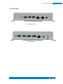
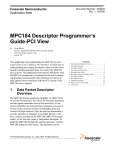
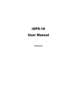
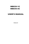
1.2.3 I/O View
SI-83 front side
SI-83 rear side
4
5
IBASE Technology Inc.
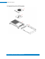
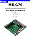
1.3 Exploded View of the SI-83 Assembly
Copyright © 2013 IBASE Technology Inc. All Rights Reserved.
SI-83 User Manual
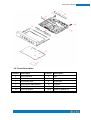
1.3.1 Parts Description
Part No.
Description
Part No.
Description
1
SI-83 heat sink
2
Fan
3
SI-83 fan bracket
4
IB983 motherboard
5
SI-83 body case
6
SI-83 base
7
SI-83 system base bracket
8
Antenna
9
SI-83 label
10
SI-83 board bracket
11
SI-83 top gasket
12/13
SI-83 I/O gasket-1/2
6
7
IBASE Technology Inc.
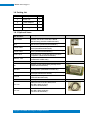
1.4 Packing List
Item No.
Description
Qty
1
Driver CD
1
2
Power adaptor
1
3
Power cord
1
4
Mounting kit
1
1.4.1 Optional Items
WiFi Solution
Description
WiFi module
Wireless; PCI-E Mini Card 802.11B/G/N
[AW-NE238H] (A008WLAWNE238H000P)
External Antenna,
2pcs
WiFi Antenna (A055RFA02C2M20800P)
Internal cable
Internal cable
Screw, 2pcs
Bracket, -1set
Internal Antenna 100mm[ BTC130-1-70B-100]
RoHS (A055RFA0000021000P)
Internal Antenna 200mm [ BTC130-1-70B-200-1]
RoHS, (A055RFA0000020000P)
Screw;A44-N NI 3.4 NYLOK M2*L3.8 P0.4mm
[LHS]RoHS (H02203A0442200N00P)
Component BOM;MPCIE-EXT V-B2 Bracket
(SC2MPCIEEXT0B2100P)
3G Solution
Description
3G
Wireless; 3.75G UMTS/HSPA [ZU202] RoHS
(A008WIRELESS00520P)
3G+GPS
Wireless; 3.75G UMTS/HSPA & GPS Module
[ZU200] RoHS (A008WIRELESS00510P)
Cable
Antenna
COM Port Cable
Cable; SMA IPX Cable For 3G 30CM [RF11030A]
RoHS (A012INTENAL010000P)
3G [ ANT0921Q2P] RoHS
(A055ANT0921Q2P000P)
Description
EXT-424
Cable;EXT-424 2-HD 8C 90CM; RJ45
Jack-8M=>DSU-9F RoHS
(C501EXT4240902000P)
EXT-481
Cable;EXT-481 2-HD 8C 90CM; RJ45
Jack-8M=>DSU-9M RoHS
(C501EXT4810902000P)
Copyright © 2013 IBASE Technology Inc. All Rights Reserved.
SI-83 User Manual
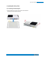
1.5 HARDWARE INSTALLATION
1.5.1 Installing the Mounting Kit
1. Please install the mounting kit and make sure the direction.
And then screw two screws as shown.
8
9
IBASE Technology Inc.
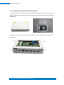
1.5.2 Installing the Optional Wireless Module
1. Remove the two screws on the back cover that are used to secure the cover to the
chassis. Once all the screws are removed, from the side, dismount the cover forward
to remove it.
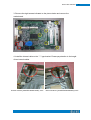
2. Remove the two screws on the base and four screws on the bracket and draw out
the chassis.
Copyright © 2013 IBASE Technology Inc. All Rights Reserved.
SI-83 User Manual
10
3. Remove the eight screws indicated on the picture below and remove the
motherboard.
4. Install the internal cable on the “ㄇ” type bracket. Please pay attention to the length
of two internal cables.
Internal Antenna [A055RFA0000021000P] 10cm
Internal Antenna [ A055RFA0000020000P] 20cm
11
IBASE Technology Inc.
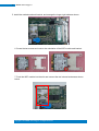
5. Install the motherboard and bracket, and arrange the longer right cable as shown.
6. Screw the two screws and note to the orientation of the WIFI module and bracket.
7. Push the WIFI module into the slot and connect the two internal antenna as shown
below.
Copyright © 2013 IBASE Technology Inc. All Rights Reserved.
SI-83 User Manual
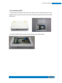
1.5.3 Installing mSATA
1. Remove the 2 screws on the back cover that are used to secure the cover to the
chassis. Once all the screws are removed, from the side, dismount the cover forward
to remove it.
2. Push the mSATA module into the slot as shown in the picture below.
12
13
IBASE Technology Inc.
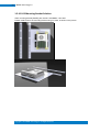
1.5.4 SI-83 Mounting Bracket Solution
SI-83 mounting bracket (IBASE) part number: SC2SIMK3---0A1100P
Please install SI-83 to the mounting bracket using 4 screws, as shown in the picture.
Copyright © 2013 IBASE Technology Inc. All Rights Reserved.
SI-83 User Manual
CHAPTER 2 MOTHERBOARD INTRODUCTION
2.1 Introduction
The IB983 CUSTOM SIGNAGE SBC is based on the latest Intel® QM87 chipset. The
platform supports onboard 4th generation Intel® Core processor family that features
an integrated dual-channel DDR3 memory controller as well as a graphics core.
The latest Intel® processors provide advanced performance in both computing and
graphics quality. This meets the requirement of customers in the gaming, POS, digital
signage and server market segment.
The QM87 platform is made with 22-nanometer technology that supports Intel’s first
processor architecture to unite the CPU and the graphics core on the transistor level.
The IB983 CUSTOM SIGNAGE SBC utilizes the dramatic increase in performance
provided by this Intel’s latest cutting-edge technology. It offers fast 6Gbps SATA
support, USB3.0 and interfaces for HDMI and DP displays.
Model
Speed
Cache
Socket
TDP
Model
Model
Configuration
Max. Support
CPU
4th Generation Intel® Core™ i7-4700EQ 2.4GHz
4th Generation Intel® Core™ i5-4400E 2.7GHz
2.4GHz and 2.7GHz
6MB / 3MB
FCBGA1364 package
TDP=47 W / 37 W
Chipset
Intel® QM87 PCH
BIOS
AMI BIOS, support ACPI Function
Memory
4GB x 2
2x DDR3 1600 MHz SO-DIMM, Max. 16GB (Non-ECC)
14
15
IBASE Technology Inc.
Display
LAN / PHY
Audio
USB
LPC I / O
Button
DC Jack
Other
Super I/O
Expansion Slot
Watchdog
H/W Monitor
iSMART
Others
PCB Dimensions
Power
Temperature
Regulation
Certification
Edge I/O
1x HDMI 1.4a
2x DP v1.3
1x GbE with Intel® WGI217LM
1x GbE with Realtek RTL8111G-CG
Intel® QM87 PCH built-in HD audio controller +
ALC892 w/ 7.1 channels
1x Audio Connector (Lin out)
2x USB 3.0; 2x USB 2.0
1x RS-232 (recessed-Mount RJ45)
1x Power Button
1x Screw type) Power Jack (+12V DC)
1x LED for Power
1x Smart DC fan (12V DC)
Internal I/O
NCT 5523D Super I/O
CPU Temp + Temp monitor +Voltage Monitor
1x mSATA, 1x mPCIe(x1) only
1x UIM/SIM card slot (for 3G/LTE adapter in mPCIe
slot)
Add-On Feature
Yes (256 segments, 0, 1, 2…255 sec/min)
YES
YES
LAN Wakeup, iSmart, Vpro (9965), & TPM
Dimensions
155mm(W) x 108mm(D)
Power
Power Jack (+12V DC)
Environmental
Operating Temperature : 0°C~60°C (32°F~140°F)
Storage Temperature : -20°C~80°C (-4°F~176°F)
RoHS
CE/FCC Class A (Target B) UL, CCC
Copyright © 2013 IBASE Technology Inc. All Rights Reserved.
SI-83 User Manual
IB983 Jumpers and Connectors
16
17
IBASE Technology Inc.
Board Dimensions
Copyright © 2013 IBASE Technology Inc. All Rights Reserved.
SI-83 User Manual
2.2 Installations
2.2.1 Installing the Memory
The IB983 board supports two DDR3 memory sockets for a maximum total memory of
16GB DDR3 memory type.
Installing and Removing Memory Modules
To install the DDR3 modules, locate the memory slot on the board and perform the
following steps:
1. Hold the DDR3 module so that the key of the DDR3 module aligned with that on the
memory slot.
2. Gently push the DDR3 module in an upright position until the clips of the slot close
to hold the DDR3 module in place when the DDR3 module touches the bottom of
the slot.
3. To remove the DDR3 module, press the clips with both hands.
18
19
IBASE Technology Inc.
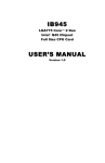
2.3 Setting the Jumpers
Jumper Locations on IB983
JP1: Clear CMOS Contents
3
1
JP1
Setting
Pin 1-2
Short/Closed
Pin 2-3
Short/Closed
Function
Normal
Clear CMOS
JP2: Clear ME Contents
3
1
Copyright © 2013 IBASE Technology Inc. All Rights Reserved.
SI-83 User Manual
J18
Setting
Pin 1-2
Short/Closed
Pin 2-3
Short/Closed
Function
Normal
Clear CMOS
20
21
IBASE Technology Inc.
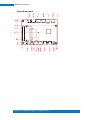
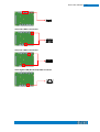
2.4 Connectors on IB983
Connector Locations on IB983
CN1: Board Input Power(12V) Connector
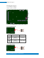
CN2: Console Port ( COM1)
8
1
The console port is an RJ45 RS-232 serial port.
Pin #
Signal Name
1
RTS
2
DTR
3
TXD
4
GND
5
GND
6
RXD
7
DSR
8
CTS
CN3, CN4: Display Port
Copyright © 2013 IBASE Technology Inc. All Rights Reserved.
SI-83 User Manual
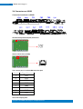
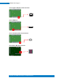
CN5, CN8: USB2.0 Connector
CN6, CN7: USB3.0 Connector
CN9: Gigabit LAN (RTL8111G) RJ45 Connector
22
23
IBASE Technology Inc.
CN10: Gigabit LAN (I217) RJ45 Connector
CN11: HDMI Port
CN12: HD Audio (Audio out) Connector
CN13: Micro SIM Card Connector
Copyright © 2013 IBASE Technology Inc. All Rights Reserved.
SI-83 User Manual
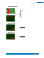
J1, J9: DDR3 SO-DIMM Socket
J4: Mini PCIE Connector
J5: mSATA Connector
24
25
IBASE Technology Inc.
J7: CPU Fan Power Connector
3
1
Pin #
Signal Name
1
Ground
2
+12V
3
Rotation detection
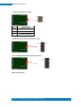
J8: SPI Flash Connector (Factory use only)
10
9
2
1
J10: LPC debug Connector (Factory use only)
10
9
2
1
SW1: Power Switch
Copyright © 2013 IBASE Technology Inc. All Rights Reserved.
SI-83 User Manual
CHAPTER 3 BIOS SETUP
This chapter describes the different settings available in the AMI BIOS that comes
with the board. The topics covered in this chapter are as follows:
3.1 BIOS Introduction
The BIOS (Basic Input/Output System) installed in your computer system’s ROM
supports Intel processors. The BIOS provides critical low-level support for a standard
device such as disk drives, serial ports and parallel ports. It also password protection
as well as special support for detailed fine-tuning of the chipset controlling the entire
system.
3.2 BIOS Setup
The BIOS provides a Setup utility program for specifying the system configurations
and settings. The BIOS ROM of the system stores the Setup utility. When you turn on
the computer, the BIOS is immediately activated. Pressing the <Del> key immediately
allows you to enter the Setup utility. If you are a little bit late pressing the <Del> key,
POST (Power On Self Test) will continue with its test routines, thus preventing you
from invoking the Setup. If you still wish to enter Setup, restart the system by pressing
the ”Reset” button or simultaneously pressing the <Ctrl>, <Alt> and <Delete> keys.
You can also restart by turning the system Off and back On again. The following
message will appear on the screen:
Press <DEL> to Enter Setup
In general, you press the arrow keys to highlight items, <Enter> to select, the <PgUp>
and <PgDn> keys to change entries, <F1> for help and <Esc> to quit.
When you enter the Setup utility, the Main Menu screen will appear on the screen.
The Main Menu allows you to select from various setup functions and exit choices.
26
27
IBASE Technology Inc.
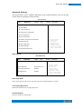
Warning:
It is strongly recommended that you avoid making any changes to the
chipset defaults. These defaults have been carefully chosen by both
AMI and your system manufacturer to provide the absolute maximum
performance and reliability. Changing the defaults could cause the
system to become unstable and crash in some cases.
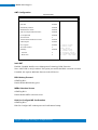
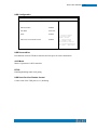
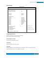
Main Settings
Aptio Setup Utility – Copyright © 2013 American Megatrends, Inc.
Main
Advanced
Chipset
Boot
BIOS Information
Security
Save & Exit
Choose the system default
language
Total Memory
4096 MB (DDR3)
Memory Frequency
1333 Mhz
System Date
[Tue 01/20/2009]
System Time
[21:52:06]
Access Level
Administrator
System Date
Set the Date. Use Tab to switch between Data elements.
System Time
Set the Time. Use Tab to switch between Data elements.
Copyright © 2013 IBASE Technology Inc. All Rights Reserved.
→ ← Select Screen
↑↓ Select Item
Enter: Select
+- Change Field
F1: General Help
F2: Previous Values
F3: Optimized Default
F4: Save
ESC: Exit
SI-83 User Manual
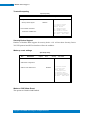
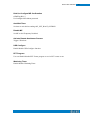
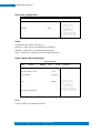
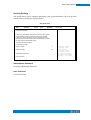
Advanced Settings
This section allows you to configure and improve your system and allows you to set up some
system features according to your preference.
Aptio Setup Utility
Main
Advanced
Chipset
Boot
Security
Save & Exit
► ACPI Settings
► Trusted Computing
► Wakeup Event Configuration
► CPU Configuration
► SATA Configuration
► Shutdown Temperature Configuration
→ ← Select Screen
↑↓ Select Item
Enter: Select
+- Change Field
F1: General Help
F2: Previous Values
F3: Optimized Default
F4: Save
ESC: Exit
► iSmart Controller
► AMT Configuration
► USB Configuration
► NCT5523D H/W Monitor
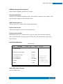
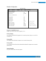
ACPI Settings
Aptio Setup Utility
Main
Advanced
Chipset
Boot
Security
Save & Exit
ACPI Settings
ACPI Sleep State
S3 (Suspend to R…)
Lock Legacy Resources
Disabled
S3 Video Repost
Disabled
→ ← Select Screen
↑↓ Select Item
Enter: Select
+- Change Field
F1: General Help
F2: Previous Values
F3: Optimized Default
F4: Save
ESC: Exit
ACPI Sleep State
Select ACPI sleep state the system will enter, when the SUSPEND button is pressed.
Lock Legacy Resources
Enabled or Disabled Lock of Legacy Resources.
S3 Video Repost
Enable or disable S3 Video Repost.
28
29
IBASE Technology Inc.
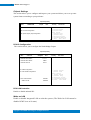
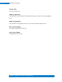
Trusted Computing
Aptio Setup Utility
Main
Advanced
Chipset
Boot
Security
Save & Exit
Configuration
Security Device Support
Disabled
→ ← Select Screen
↑↓ Select Item
Enter: Select
+- Change Field
F1: General Help
F2: Previous Values
F3: Optimized Default
F4: Save
ESC: Exit
Current Status Information
SUPPORT TURNED OFF
Security Device Support
Enables or Disables BIOS support for security device. O.S. will not show Security Device.
TCG EFI protocol and INT1A interface will not be available.
Wake up event settings
Aptio Setup Utility
Main
Advanced
Chipset
Boot
Security
Save & Exit
Wake Event Configuration
Wake on PCIE Wake Event
Disabled
Wake on PCIE Wake Event
The options are Disabled and Enabled.
Copyright © 2013 IBASE Technology Inc. All Rights Reserved.
→ ← Select Screen
↑↓ Select Item
Enter: Select
+- Change Field
F1: General Help
F2: Previous Values
F3: Optimized Default
F4: Save
ESC: Exit
SI-83 User Manual
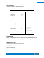
CPU Configuration
This section shows the CPU configuration parameters.
Aptio Setup Utility
Main
Advanced
Chipset
Boot
Security
Save & Exit
CPU Configuration
Intel(R) CPU Core(TM)i7-4700EQE @ 2.40GHz
CPU Signature
306c3
Processor Family
6
Microcode Patch
17
FSB Speed
100MHz
Max CPU Speed
2400 MHz
Min CPU Speed
800 MHz
CPU Speed
2400 MHz
Processor Cores
4
Intel HT Technology
Supported
Intel VT-x Technology
Supported
Intel SMX Technology
Supported
64-bit
Supported
EIST
Supported
Hyper-threading
Enable
Active Processor Cores
All
Limit CPUID Maximum
Disabled
Execute Disable Bit
Enabled
Intel Virtualization Technology
Enabled
EIST
Enabled
→ ← Select Screen
↑↓ Select Item
Enter: Select
+- Change Field
F1: General Help
F2: Previous Values
F3: Optimized Default
F4: Save
ESC: Exit
Hyper-threading
Enabled for Windows XP and Linux (OS optimized for Hyper-Threading Technology) and
Disabled for other OS (OS not optimized for Hyper-Threading Technology). When Disabled
only one thread per enabled core is enabled.
Active Processor Cores
Number of cores to enable in each processor package.
Limit CPUID Maximum
Disabled for Windows XP.
30
31
IBASE Technology Inc.
Execute Disable Bit
XD can prevent certain classes of malicious buffer overflow attacks when combined with a
supporting OS
Intel Virtualization Technology
When enabled, a VMM can utilize the additional hardware capabilities provided by
Vanderpool Technology.
EIST
Enabled/Disabled Intel Speedstep.
SATA Configuration
SATA Devices Configuration.
Aptio Setup Utility
Main
Advanced
Chipset
Boot
SATA Controller(s)
Enabled
SATA Mode Selection
AHCI
SATA Controller Speed
Default
Serial ATA Port 0
Empty
Software Preserve
Unknown
Hot Plug
Disabled
Security
→ ← Select Screen
↑↓ Select Item
Enter: Select
+- Change Field
F1: General Help
F2: Previous Values
F3: Optimized Default
F4: Save
ESC: Exit
SATA Controller(s)
Enable or disable SATA Device.
SATA Mode Selection
(1) IDE Mode.
(2) AHCI Mode.
SATA Controller Speed
Indicates the maximum speed the SATA controller can support.
Hot Plug
Designates this port as Hot Pluggable.
Copyright © 2013 IBASE Technology Inc. All Rights Reserved.
Save & Exit
SI-83 User Manual
Shutdown Temperature Configuration
Aptio Setup Utility
Main
Advanced
Chipset
Boot
APCI Shutdown Temperature
Security
Save & Exit
→ ← Select Screen
↑↓ Select Item
Enter: Select
+- Change Field
F1: General Help
F2: Previous Values
F3: Optimized Default
F4: Save
ESC: Exit
Disabled
ACPI Shutdown Temperature
The default setting is Disabled.
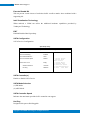
iSmart Controller
Aptio Setup Utility
Main
Advanced
Chipset
Boot
Security
Save & Exit
iSmart Controller
Power-On after Power failure
Disable
Schedule Slot 1
None
Schedule Slot 2
None
iSmart Controller
Setup the power on time for the system.
Schedule Slot 1 / 2
Setup the hour/minute for system power on.
→ ← Select Screen
↑↓ Select Item
Enter: Select
+- Change Field
F1: General Help
F2: Previous Values
F3: Optimized Default
F4: Save
ESC: Exit
32
33
IBASE Technology Inc.
AMT Configuration
Aptio Setup Utility
Main
Advanced
Chipset
Boot
Security
Intel AMT
Enabled
BIOS Hotkey Pressed
Disabled
MEBx Selection Screen
Disabled
Hide Un-Configure ME Confirmation
Disabled
Un-Configure ME
Disabled
Amt Wait Timer
0
Activate Remote Assistance Process
Disabled
USB Configure
Enabled
PET Progress
Enabled
AMT CIRA Timeout
0
Watchdog
Disabled
OS Timer
0
BIOS Timer
0
Save & Exit
→ ← Select Screen
↑↓ Select Item
Enter: Select
+- Change Field
F1: General Help
F2: Previous Values
F3: Optimized Default
F4: Save
ESC: Exit
Intel AMT
Enabled / Disabled Intel(R) Active Management Technology BIOS Extension.
Note: iAMT H/W is always enabled. This option just controls the BIOS extension execution.
If enabled, this requires additional firmware in the SPI device.
BIOS Hotkey Pressed
OEMFLag Bit 1:
Enable/Disable BIOS hotkey press.
MEBx Selection Screen
OEMFLag Bit 2:
Enable/Disable MEBx selection screen.
Hide Un-Configure ME Confirmation
OEMFLag Bit 6:
Hide Un-Configure ME without password Confirmation Prompt
Copyright © 2013 IBASE Technology Inc. All Rights Reserved.
SI-83 User Manual
Hide Un-Configure ME Confirmation
OEMFLag Bit 15:
Un-Configure ME without password
Amt Wait Timer
Set timer to wait before sending ASF_GET_BOOT_OPTIONS.
Disable ME
Set ME to Soft Temporary Disabled.
Activate Remote Assistance Process
Trigger CIRA boot.
USB Configure
Enable/Disable USB Configure function.
PET Progress
User can Enable/Disable PET Events progress to receive PET events or not.
Watchdog Timer
Enable/Disable Watchdog Timer.
34
35
IBASE Technology Inc.
USB Configuration
Aptio Setup Utility
Main
Advanced
Chipset
Boot
Security
Save & Exit
USB Configuration
USB Module Version
8.10.28
USB Devices:
Legacy USB Support
Enabled
USB3.0 Support
Enabled
XHCI Hand-off
Enabled
EHCI Hand-off
Enabled
USB Mass Storage Driver Support
Enabled
Port 60/64 Emulation
Enabled
USB hardware delays and time-outs:
USB Transfer time-out
20 sec
Device reset tine-out
20 sec
Device power-up delay
Auto
→ ← Select Screen
↑↓ Select Item
Enter: Select
+- Change Field
F1: General Help
F2: Previous Values
F3: Optimized Default
F4: Save
ESC: Exit
Legacy USB Support
Enables Legacy USB support.
AUTO option disables legacy support if no USB devices are connected.
DISABLE option will keep USB devices available only for EFI applications.
USB3.0 Support
Enable/Disable USB3.0 (XHCI) Controller support.
XHCI Hand-off
This is a workaround for OSes without XHCI hand-off support. The XHCI ownership change
should be claimed by XHCI driver.
EHCI Hand-off
Enabled/Disabled. This is a workaround for OSes without EHCI hand-off support. The EHCI
ownership change should be claimed by EHCI driver.
Copyright © 2013 IBASE Technology Inc. All Rights Reserved.
SI-83 User Manual
USB Mass Storage Driver Support
Enable/Disable USB Mass Storage Driver Support.
Port 60/64 Emulation
Enables I/O port 60h/64h emulation support. This should be enabled for the complete USB
keyboard legacy support for non-USB aware OSes.
USB Transfer time-out
The time-out value for Control, Bulk, and Interrupt transfers.
Device reset tine-out
USB mass Storage device start Unit command time-out.
Device power-up delay
Maximum time the device will take before it properly reports itself to the Host Controller.
‘Auto’ uses default value: for a Root port it is 100ms, for a Hub port the delay is taken from
Hub descriptor.
NCT5523D HW Monitor
Aptio Setup Utility
Main
Advanced
Chipset
Boot
Security
Save & Exit
PC Health Status
Smart CPU_FAN1 function
Disabled
SYS Thermistor Temp
+37.0 C
CPU Diode Temp
+42.5 C
CPU_FAN Speed
4440 RPM
VCORE
+1.768 V
VDDQ
+1.520
Smart CPU_FAN1 Function
Smart Fan Mode select
→ ← Select Screen
↑↓ Select Item
Enter: Select
+- Change Field
F1: General Help
F2: Previous Values
F3: Optimized Default
F4: Save
ESC: Exit
36
37
IBASE Technology Inc.
Chipset Settings
This section allows you to configure and improve your system and allows you to set up some
system features according to your preference.
Aptio Setup Utility
Main
Advanced
Chipset
Boot
Security
Save & Exit
→ ← Select Screen
↑↓ Select Item
Enter: Select
+- Change Field
F1: General Help
F2: Previous Values
F3: Optimized Default
F4: Save
ESC: Exit
► PCH-IO Configuration
► System Agent (SA) Configuration
PCH-IO Configuration
This section allows you to configure the North Bridge Chipset.
Aptio Setup Utility
Main
Advanced
Chipset
Boot
Intel PCH RC Version
1.7.0.0
Intel PCH SKU Name
QM87
Intel PCH Rev ID
05/C2
Security
Save & Exit
► USB Configuration
► PCH Azalia Configuration
PCH LAN Controller
Wake on LAN
Enabled
Disabled
→ ← Select Screen
↑↓ Select Item
Enter: Select
+- Change Field
F1: General Help
F2: Previous Values
F3: Optimized Default
F4: Save
ESC: Exit
PCH LAN Controller
Enable or disable onboard NIC.
Wake on LAN
Enable or disable integrated LAN to wake the system. (The Wake On LAN cannot be
disabled if ME is on at Sx state.)
Copyright © 2013 IBASE Technology Inc. All Rights Reserved.
SI-83 User Manual
USB Configuration
Main
Advanced
Chipset
Boot
Security
Save & Exit
USB Configuration
USB Precondition
Disabled
xHCI Mode
Smart Auto
BTCG
Enabled
USB Ports Per-Port Disable Control
Disabled
→ ← Select Screen
↑↓ Select Item
Enter: Select
+- Change Field
F1: General Help
F2: Previous Values
F3: Optimized Default
F4: Save
ESC: Exit
USB Precondition
Precondition work on USB host controller and root ports for faster enumeration.
xHCI Mode
Mode of operation of xHCI controller.
BTCG
Enabling/disabling trunk clock gating
USB Ports Per-Port Disable Control
Control each of the USB ports (0~13) disabling.
38
39
IBASE Technology Inc.
PCH Azalia Configuration
Main
Advanced
Chipset
Boot
Security
Save & Exit
PCH Azalia Configuration
Azalia
→ ← Select Screen
↑↓ Select Item
Enter: Select
+- Change Field
F1: General Help
F2: Previous Values
F3: Optimized Default
F4: Save
ESC: Exit
Auto
Azalia
Control Detection of the Azalia device.
Disabled = Azalia will be unconditionally be disabled.
Enabled = Azalia will be unconditionally be enabled.
Auto = Azalia will be enabled if present, disabled otherwise.
System Agent (SA) Configuration
Aptio Setup Utility
Main
Advanced
Chipset
System Agent Bridge Name
Boot
Security
Save & Exit
Haswell
System Agent RC Version
1.5.0.0
VT-d Capability
Supported
VT-d
Enabled
► Graphics Configuration
VT-d
Check to enable VT-d function on MCH.
Copyright © 2013 IBASE Technology Inc. All Rights Reserved.
→ ← Select Screen
↑↓ Select Item
Enter: Select
+- Change Field
F1: General Help
F2: Previous Values
F3: Optimized Default
F4: Save
ESC: Exit
SI-83 User Manual
Graphics Configuration
Aptio Setup Utility
Main
Advanced
Chipset
Boot
Security
Save & Exit
Graphics Configuration
IGFX VBIOS Version
2167
IGfx Frequency
800 MHz
Graphics Turbo IMON Current
31
Primary Display
Auto
Primary PEG
Auto
Primary PCIE
Auto
Internal Graphics
Auto
Aperture Size
256MB
DVMT Pre-Allocated
32M
DVMT Total Gfx Mem
256MB
Gfx Low Power Mode
Enabled
Panel Power Enable
Disabled
→ ← Select Screen
↑↓ Select Item
Enter: Select
+- Change Field
F1: General Help
F2: Previous Values
F3: Optimized Default
F4: Save
ESC: Exit
Graphics Turbo IMON Current
Graphics turbo Imon current values supported (14-31)
Primary Display
Select which of IGFX/PEG/PCI graphics device should be primary display or select SG for
switchable Gfx.
Primary PEG
Select PEGO/PEG1/PEG2/PEG3 Graphics device should be Primary PEG.
Primary PCIE
Select PCIE0/PCIE1/PCIE2/PCIE3/PCIE4/PCIE5/PCIE6PCIE7 Graphics device should be
primary PCIE.
Internal Graphics
Keep IGD enabled based on the setup options.
40
41
IBASE Technology Inc.
Aperture Size
Select the Aperture Size
DVMT Pre-Allocated
Select DVMT 5.0 Pre-Allocated (Fixed) Graphics memory size used by the internal graphics
device.
DVMT Total Gfx Mem
Select DVMT 5.0 total graphics memory size used by the internal graphics device.
Gfx Low Power Mode
This option is applicable for SFF only.
Panel Power Enable
This applicable for SFF only
Copyright © 2013 IBASE Technology Inc. All Rights Reserved.
SI-83 User Manual
Boot Settings
Aptio Setup Utility
Main
Advanced
Chipset
Boot
Security
Save & Exit
Boot Configuration
Setup Prompt Timeout
1
Bootup NumLock State
On
Quiet Boot
Disabled
Fast Boot
Disabled
Set Boot Priority
1st Boot
CD/DVD
2nd Boot
3rd Boot
Hard Disk
USb Floppy
4th Boot
USB CD/DVD
5th Boot
USB Hard Disk
6th Boot
USB KEY
7th Boot
Network
8th Boot
UEFI
Boot Option Priorities
Boot Option #1
► CSM16 Parameters
CSM Parameters
→ ← Select Screen
↑↓ Select Item
Enter: Select
+- Change Field
F1: General Help
F2: Previous Values
F3: Optimized Default
F4: Save
ESC: Exit
► Hard Disk Drive BBS Priorities
Setup Prompt Timeout
Number of seconds to wait for setup activation key.
65535(0xFFFF) means indefinite waiting.
Bootup NumLock State
Select the keyboard NumLock state.
Quiet Boot
Enables or disables Quiet Boot option.
Fast Boot
Enables or disables boot with initialization of a minimal set of devices required to launch
active boot option. Has no effect for BBS boot options.
42
43
IBASE Technology Inc.
Set Boot Priority
Set Boot Priority
Boot Option Priorities
Sets the system boot order.
CSM parameters
This section allows you to configure the boot settings.
Aptio Setup Utility
Main
Advanced
Chipset
Boot
Security
Launch CSM
Enabled
Boot option filter
UEFI and Legacy
Launch PXE OpROM policy
Do not launch
Launch Storage OpROM policy
Legacy only
Launch Video OpROM policy
Legacy only
Other PCI device ROM priority
UEFI OpROM
Save & Exit
→ ← Select Screen
↑↓ Select Item
Enter: Select
+- Change Field
F1: General Help
F2: Previous Values
F3: Optimized Default
F4: Save
ESC: Exit
Launch CSM
This option controls if CSM will be launched.
Boot Option Filter
This option controls what devices system can boot to.
Launch PXE OpROM Policy
Controls the execution of UEFI and Legacy PXE OpROM.
Launch Storatge OpROM Policy
Controls the execution of UEFI and Legacy Storage OpROM.
Launch Video OpROM Policy
Controls the execution of UEFI and Legacy Video OpROM.
Other PCI Device ROM Priority
For PCI devices other than Network, Mass storage or Video defines which OpROM to launch.
Copyright © 2013 IBASE Technology Inc. All Rights Reserved.
SI-83 User Manual
Security Settings
This section allows you to configure and improve your system and allows you to set up some
system features according to your preference.
Aptio Setup Utility
Main
Advanced
Chipset
Boot
Security
Save & Exit
Password Description
If ONLY the Administrator’s password is set, then this only limit
access to Setup and is only asked for when entering Setup.
If ONLY the User’s password is set, then this is a power on
password and must be entered to boot or enter Setup. In Setup
the User will have Administrator rights
The password length must be
in the following range:
Minimum length
3
Maximum length
20
Administrator Password
User Password
Administrator Password
Set Setup Administrator Password.
User Password
Set User Password.
→ ← Select Screen
↑↓ Select Item
Enter: Select
+- Change Field
F1: General Help
F2: Previous Values
F3: Optimized Default
F4: Save
ESC: Exit
44
45
IBASE Technology Inc.
Save & Exit Settings
Aptio Setup Utility
Main
Advanced
Chipset
Boot
Security
Save & Exit
Save Changes and Exit
Discard Changes and Exit
Save Changes and Reset
Discard Changes and Reset
Save Options
Save Changes
Discard Changes
Restore Defaults
Save as User Defaults
Restore User Defaults
Save Changes and Exit
Exit system setup after saving the changes.
Discard Changes and Exit
Exit system setup without saving any changes.
Save Changes and Reset
Reset the system after saving the changes.
Discard Changes and Reset
Reset system setup without saving any changes.
Save Changes
Save Changes done so far to any of the setup options.
Discard Changes
Discard Changes done so far to any of the setup options.
Restore Defaults
Restore/Load Defaults values for all the setup options.
Save as User Defaults
Save the changes done so far as User Defaults.
Restore User Defaults
Restore the User Defaults to all the setup options.
Copyright © 2013 IBASE Technology Inc. All Rights Reserved.
→ ← Select Screen
↑↓ Select Item
Enter: Select
+- Change Field
F1: General Help
F2: Previous Values
F3: Optimized Default
F4: Save
ESC: Exit
SI-83 User Manual
CHAPTER 4 DRIVERS INSTALLATION
The Intel Chipset Drivers should be installed first before the software drivers to
enable Plug & Play INF support for Intel chipset components. Follow the instructions
below to complete the installation.
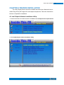
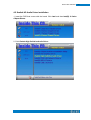
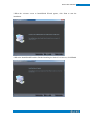
4.1 Intel Chipset Software Installation Utility
1. Insert the DVD that comes with the board. Click Intel and then Intel(R) 8 Series Chipset Drivers.
2. Click Intel(R) Chipset Software Installation Utility.
46
47
IBASE Technology Inc.
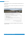
3. When the Welcome screen to the Intel® Chipset Device Software appears, click
Next to continue.
4. Click Yes to accept the software license agreement and proceed with the
installation process.
5. On the Readme File Information screen, click Next to continue the installation.
6. The Setup process is now complete. Click Finish to restart the computer and for
changes to take effect.
Copyright © 2013 IBASE Technology Inc. All Rights Reserved.
SI-83 User Manual
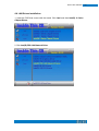
4.2 VGA Drivers Installation
1. Insert the DVD that comes with the board. Click Intel and then Intel(R) 8 Series
Chipset Drivers.
2. Click Intel(R) Core(TM) i3/i5/i7 Graphics Driver.
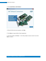
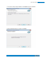
3. When the Welcome screen appears, click Next to continue.
4. Click Yes to to agree with the license agreement and continue the installation.
48
49
IBASE Technology Inc.
5. On the screen shown below, click Install to continue.
6. Setup complete. Click Finish to restart the computer and for changes to take effect.
Copyright © 2013 IBASE Technology Inc. All Rights Reserved.
SI-83 User Manual
4.3 Realtek HD Audio Driver Installation
1. Insert the DVD that comes with the board. Click Intel and then Intel(R) 8 Series
Chipset Drivers.
2. Click Realtek High Definition Audio Driver.
50
51
IBASE Technology Inc.
3. On the Welcome to the InstallShield Wizard screen, click Yes to proceed with and
complete the installation process.
4. The InstallShield Wizard Complete.
Click Finish to restart the computer and for
changes to take ffect.
Copyright © 2013 IBASE Technology Inc. All Rights Reserved.
SI-83 User Manual
4.4 LAN Drivers Installation
1. Insert the DVD that comes with the board. Click Intel and then Intel(R) 8 Series
Chipset Drivers.
2. Click Intel(R) PRO LAN Network Driver.
52
53
IBASE Technology Inc.
3. Click Install Drivers and Software.
4. When the Welcome screen appears, click Next.
5. Click Next to to agree with the license agreement.
6. Click the checkbox for Drivers in the Setup Options screen to select it and click
Next to continue.
Copyright © 2013 IBASE Technology Inc. All Rights Reserved.
SI-83 User Manual
7. The wizard is ready to begin installation. Click Install to begin the installation.
8. When InstallShield Wizard is complete, click Finish.
54
55
IBASE Technology Inc.
4.5 Realtek LAN Controller Drivers Installation
Follow the steps below to install the Realtek LAN Drivers.
1. Insert the CD that comes with the board. Click LAN Card, and then Realtek Lan
Controller Drivers.
2. Click Realtek RTL8111E LAN Drivers.
Copyright © 2013 IBASE Technology Inc. All Rights Reserved.
SI-83 User Manual
3.When the welcome screen to InstallShield Wizard appears, click Next to start the
installation.
4.When the InstallShieldWizard has finished installing the Realtek LAN drivers, click Finish.
56
57
IBASE Technology Inc.
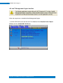
4.6 Intel® Management Engine Interface
Follow the steps below to install the Intel Management Engine.
1. Insert the DVD that comes with the board. Click Intel and then Intel(R) 8 Series Chipset
Drivers and then Intel(R) AMT 9.0 Drivers.
Copyright © 2013 IBASE Technology Inc. All Rights Reserved.
SI-83 User Manual
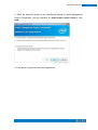
2. When the Welcome screen to the InstallShield Wizard for Intel® Management
Engine Components, click the checkbox for Install Intel® Control Center & click
Next.
3. Click Yes to to agree with the license agreement.
58
59
IBASE Technology Inc.
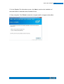
4. When the Setup Progress screen appears, click Next. Then, click Finish when the
setup progress has been successfully installed.
Copyright © 2013 IBASE Technology Inc. All Rights Reserved.
SI-83 User Manual
4.7 Intel® USB 3.0 Drivers
1. Insert the DVD that comes with the board. Click Intel and then Intel(R) 8 Series
Chipset Drivers.
2. Click Intel(R) USB 3.0 Drivers.
60
61
IBASE Technology Inc.
3. When the Welcome screen to the InstallShield Wizard for Intel® USB 3.0
eXtensible Host Controller Driver, click Next.
4. Click Yes to to agree with the license agreement and continue the installation.
Copyright © 2013 IBASE Technology Inc. All Rights Reserved.
SI-83 User Manual
5. On the Readme File Information screen, click Next to continue the installation of
the Intel® USB 3.0 eXtensible Host Controller Driver.
6. Setup complete. Click Finish to restart the computer and for changes to take effect.
62
63
IBASE Technology Inc.
Appendix
A. I/O Port Address Map
Each peripheral device in the system is assigned a set of I/O port addresses which
also becomes the identity of the device. The following table lists the I/O port
addresses used.
Address
Device Description
0000h-001Fh
Direct memory access controller
0000h-0001h
PCI bus
0040h-0043h
System timer
0050h-0053h
System timer
0070h-0077h
System CMOS/real time clock
0081h-0091h
Direct memory access controller
0093h-009Fh
Direct memory access controller
00C0h-00DFh
Direct memory access controller
00F0h-00F0h
Numeric data processor
03B0h-03BBh
Intel(R) HD Graphics 4600
03C0h-03DFh
Intel(R) HD Graphics 4600
03F8h-03FFh
Communications Port (COM1)
0D00h-FFFFh
PCI bus
E000h-EFFFh
Intel(R) 8 Series/C220 Series PCI Express Root Port #7 - 8C1C
F000h-F03Fh
Intel(R) HD Graphics 4600
F040h-F05Fh
Intel(R) 8 Series/C220 Series SMBus Controller - 8C22
F0E0h-F0E7h
Intel(R) Active Management Technology - SOL (COM3)
Copyright © 2013 IBASE Technology Inc. All Rights Reserved.
SI-83 User Manual
B. Interrupt Request Lines (IRQ)
Peripheral devices use interrupt request lines to notify CPU for the service required.
The following table shows the IRQ used by the devices on board.
Level
Function
IRQ0
System timer
IRQ4
Serial Port #1
IRQ8
System CMOS / real time clock
IRQ11
Intel(R) 8 Series/C220 Series SMBus Controller
-8C22
IRQ13
Numeric data processor
IRQ16
Intel(R) 8 Series/C220 Series USB EHCI#2 -8C2D
IRQ19
Intel(R) 8 Series 4 port Serial ATA Storage Controller
-8C01
IRQ22
High Definition Audio Controller
IRQ23
Intel(R) 8 Series/C220 Series USB EHCI#1-8C26
64
65
IBASE Technology Inc.
C. Watchdog Timer Configuration
The WDT is used to generate a variety of output signals after a user programmable count. The
WDT is suitable for use in the prevention of system lock-up, such as when software becomes
trapped in a deadlock. Under these sorts of circumstances, the timer will count to zero and the
selected outputs will be driven. Under normal circumstance, the user will restart the WDT at
regular intervals before the timer counts to zero.
SAMPLE CODE:
File of the NCT5523D.H
//--------------------------------------------------------------------------//
// THIS CODE AND INFORMATION IS PROVIDED "AS IS" WITHOUT WARRANTY OF ANY
// KIND, EITHER EXPRESSED OR IMPLIED, INCLUDING BUT NOT LIMITED TO THE
// IMPLIED WARRANTIES OF MERCHANTABILITY AND/OR FITNESS FOR A PARTICULAR
// PURPOSE.
//
//--------------------------------------------------------------------------#ifndef __NCT5523D_H
#define __NCT5523D_H
1
//--------------------------------------------------------------------------#define
NCT5523D_INDEX_PORT
(NCT5523D_BASE)
#define
NCT5523D_DATA_PORT
(NCT5523D_BASE+1)
//--------------------------------------------------------------------------#define
NCT5523D_REG_LD
0x07
//--------------------------------------------------------------------------#define
NCT5523D_UNLOCK
0x87
#define
NCT5523D_LOCK
0xAA
//--------------------------------------------------------------------------unsigned int Init_NCT5523D(void);
void Set_NCT5523D_LD( unsigned char);
void Set_NCT5523D_Reg( unsigned char, unsigned char);
unsigned char Get_NCT5523D_Reg( unsigned char);
//--------------------------------------------------------------------------#endif
//__NCT5523D_H
Copyright © 2013 IBASE Technology Inc. All Rights Reserved.
SI-83 User Manual
File of the MAIN.CPP.
//--------------------------------------------------------------------------//
// THIS CODE AND INFORMATION IS PROVIDED "AS IS" WITHOUT WARRANTY OF ANY
// KIND, EITHER EXPRESSED OR IMPLIED, INCLUDING BUT NOT LIMITED TO THE
// IMPLIED WARRANTIES OF MERCHANTABILITY AND/OR FITNESS FOR A PARTICULAR
// PURPOSE.
//
//--------------------------------------------------------------------------#include <dos.h>
#include <conio.h>
#include <stdio.h>
#include <stdlib.h>
#include "NCT5523D.H"
//--------------------------------------------------------------------------int main (void);
void WDTInitial(void);
void WDTEnable(unsigned char);
void WDTDisable(void);
66
67
IBASE Technology Inc.
//--------------------------------------------------------------------------int main (void)
{
char SIO;
SIO = Init_NCT5523D();
if (SIO == 0)
{
printf("Can not detect Nuvoton NCT5523D, program abort.\n");
return(1);
}
WDTInitial();
WDTEnable(10);
WDTDisable();
return 0;
}
//--------------------------------------------------------------------------void WDTInitial(void)
{
unsigned char bBuf;
Set_NCT5523D_LD(0x08);
//switch to logic device 8
bBuf = Get_NCT5523D_Reg(0x30);
bBuf &= (~0x01);
Set_NCT5523D_Reg(0x30, bBuf);
//Enable WDTO
}
//---------------------------------------------------------------------------
void WDTEnable(unsigned char NewInterval)
{
unsigned char bBuf;
Set_NCT5523D_LD(0x08);
//switch to logic device 8
Set_NCT5523D_Reg(0x30, 0x01);
//enable timer
bBuf = Get_NCT5523D_Reg(0xF0);
bBuf &= (~0x08);
Set_NCT5523D_Reg(0xF0, bBuf);
Copyright © 2013 IBASE Technology Inc. All Rights Reserved.
//count mode is second
SI-83 User Manual
Set_NCT5523D_Reg(0xF1, NewInterval);
//set timer
}
//--------------------------------------------------------------------------void WDTDisable(void)
{
Set_NCT5523D_LD(0x08);
//switch to logic device 8
Set_NCT5523D_Reg(0xF1, 0x00);
//clear watchdog timer
Set_NCT5523D_Reg(0x30, 0x00);
//watchdog disabled
}
//---------------------------------------------------------------------------
File of the NCT5523D.CPP
//--------------------------------------------------------------------------//
// THIS CODE AND INFORMATION IS PROVIDED "AS IS" WITHOUT WARRANTY OF ANY
// KIND, EITHER EXPRESSED OR IMPLIED, INCLUDING BUT NOT LIMITED TO THE
// IMPLIED WARRANTIES OF MERCHANTABILITY AND/OR FITNESS FOR A PARTICULAR
// PURPOSE.
//
//--------------------------------------------------------------------------#include "NCT5523D.H"
#include <dos.h>
//--------------------------------------------------------------------------unsigned int NCT5523D_BASE;
68
69
IBASE Technology Inc.
void Unlock_NCT5523D (void);
void Lock_NCT5523D (void);
//--------------------------------------------------------------------------unsigned int Init_NCT5523D(void)
{
unsigned int result;
unsigned char ucDid;
NCT5523D_BASE = 0x4E;
result = NCT5523D_BASE;
ucDid = Get_NCT5523D_Reg(0x20);
if (ucDid == 0xC4)
{
goto Init_Finish;
//NCT5523D??
}
NCT5523D_BASE = 0x2E;
result = NCT5523D_BASE;
ucDid = Get_NCT5523D_Reg(0x20);
if (ucDid == 0xC4)
{
goto Init_Finish;
//NCT5523D??
}
NCT5523D_BASE = 0x00;
result = NCT5523D_BASE;
Init_Finish:
return (result);
}
//--------------------------------------------------------------------------void Unlock_NCT5523D (void)
{
outportb(NCT5523D_INDEX_PORT, NCT5523D_UNLOCK);
outportb(NCT5523D_INDEX_PORT, NCT5523D_UNLOCK);
}
//--------------------------------------------------------------------------void Lock_NCT5523D (void)
{
outportb(NCT5523D_INDEX_PORT, NCT5523D_LOCK);
}
Copyright © 2013 IBASE Technology Inc. All Rights Reserved.
SI-83 User Manual
//---------------------------------------------------------------------------
void Set_NCT5523D_LD( unsigned char LD)
{
Unlock_NCT5523D();
outportb(NCT5523D_INDEX_PORT, NCT5523D_REG_LD);
outportb(NCT5523D_DATA_PORT, LD);
Lock_NCT5523D();
}
//--------------------------------------------------------------------------void Set_NCT5523D_Reg( unsigned char REG, unsigned char DATA)
{
Unlock_NCT5523D();
outportb(NCT5523D_INDEX_PORT, REG);
outportb(NCT5523D_DATA_PORT, DATA);
Lock_NCT5523D();
}
//--------------------------------------------------------------------------unsigned char Get_NCT5523D_Reg(unsigned char REG)
{
unsigned char Result;
Unlock_NCT5523D();
outportb(NCT5523D_INDEX_PORT, REG);
Result = inportb(NCT5523D_DATA_PORT);
Lock_NCT5523D();
return Result;
}
//---------------------------------------------------------------------------
70