1
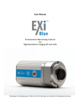
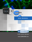
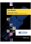
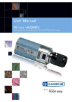
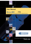
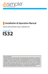
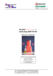
Rolera Bolt USER MANUAL
Applicability
This document applies to the Rolera Bolt camera. For the latest updates, please visit www.qimaging.com.
Notice of Copyright
Copyright © 2013 Quantitative Imaging Corporation. All rights reserved. Unauthorized duplication of this
document is prohibited.
Trademarks and Proprietary Names
QImaging, Rolera Bolt, and QCapture are trademarks of QImaging. Product names mentioned in this document
may be trademarks or registered trademarks of QImaging or other hardware, software, or service providers
and are used herein for identification purposes only. Microsoft® and Windows® are registered trademarks in
the U.S. and other countries of Microsoft Corporation and are used herein for identification purposes only.
Apple®and Macintosh® are registered in the U.S. and other countries by Apple Computer, Inc. and are used
herein for identification purposes only.
QImaging Corporation Address Information
19535 56th Avenue,
Suite 101
Surrey, BC, Canada V3S 6K3
604.530.5800
www.qimaging.com
QImaging Technical Support
Technical support is available to all registered users of QImaging products from 9am to 5pm Pacific
Standard Time.
[email protected]
800.874.9789
http://www.qimaging.com/support
www.qimaging.com
©2013 QImaging. All rights reserved. QI_BOLT_UM_RevA1
Rolera Bolt USER MANUAL
QIMAGING LIMITED WARRANTY
Standard Product Warranty Plan
A Standard Product Warranty Plan is included with every QImaging camera purchase. This Warranty Plan
includes parts and labor for two full years! The Standard Product Warranty Plan is provided on all new and
used equipment, including retired demonstration cameras.
Extended Product Warranty Plan
Extended Product Warranty Plans are conveniently priced and very easy to purchase. Available for all QImaging
cameras, the Extended Product Warranty Plan includes parts and labor and is available in one-year increments
up to five years. If needed, QImaging also offers a Camera Loan Program.
When you purchase an Extended Product Warranty Plan from QImaging, you are assured of our commitment
to minimizing down times. Your needs are our top priority and we respond to them immediately. The QImaging
service and support team is focused on expediting your request to provide a fast and complete solution.
QImaging also offers on-site training as well as online operational training programs. These programs are
designed to get you up and running with your new camera quickly and efficiently.
Contact a QImaging Representative to learn more about Extended Product Warranty Plan options from
QImaging.
www.qimaging.com
©2013 QImaging. All rights reserved. QI_BOLT_UM_RevA1
Rolera Bolt USER MANUAL
Table of Contents
INTRODUCTION .............................................................................................................. 1
Power Requirements .......................................................................................................... 1
Host Requirements.............................................................................................................. 1
USB 2.0 Interface .............................................................................................................. 2
Cables ................................................................................................................................ 2
Imaging Software for Your Camera .................................................................................... 2
INSTALLATION ................................................................................................................ 3
Step 1. Install Your Imaging Software ................................................................................. 3
Step 2. Connect the Rolera Bolt ......................................................................................... 3
Connecting the the camera to a PC/MAC desktop computer .............................................. 3
CAMERA BASICS.............................................................................................................. 5
Turning the Camera On and Off ......................................................................................... 5
Connecting the Rolera Bolt to Your Optics ........................................................................ 5
Understanding the LED Indicators........................................................................................ 6
Capturing Images with the Rolera Bolt ............................................................................... 6
Basic Camera Parameters.................................................................................................... 6
Gain Controls ..................................................................................................................... 6
Exposure Controls .............................................................................................................. 6
CARING FOR YOUR CAMERA ........................................................................................ 7
TROUBLESHOOTING ....................................................................................................... 8
Resolving Problems with the Camera................................................................................... 8
Unresolved Problems - Contacting QImaging Support ......................................................... 9
GLOSSARY..................................................................................................................... 10
APPENDICES................................................................................................................... 12
APPENDIX A: Rolera Bolt Dimensions ................................................................................ 12
www.qimaging.com
©2013 QImaging. All rights reserved. QI_BOLT_UM_RevA1
Rolera Bolt USER MANUAL
CHAPTER 1
INTRODUCTION
Introducing the Rolera Bolt CMOS camera from QImaging. As a cost-effective solution, the Rolera Bolt is
designed to meet the imaging requirements for a diverse set of applications ranging from IR-DIC to whole
organism motility studies including fluorescence documentation of C. elegans and Drosophila larvae. Capable
of streaming at 30 full frames per second with 1.3 mega-pixel resolution and 3e-read noise, the Rolera Bolt is
perfect for tracking dynamic events with detailed spatial and temporal resolution. The USB 2.0 digital interface
allows easy installation with a single cable for both power and data communication and eliminates the need
for a framegrabber or external power supply. The Rolera Bolt includes QCapture Software for Windows which
offers real time image preview and capture. A Software Development Kit (SDK) is available for interfacing with
custom software.
Figure 1: The Rolera Bolt Scientific CMOS Camera
Power Requirements
The Rolera Bolt can be powered through a single USB 2.0 cable.
■■
Power: 2.5 Watts
■■
Input voltage range: 5 volts
Host Requirements
The host computer for your Rolera Bolt camera must include:
■■
The host computer for your Rolera Bolt camera must include:
■■
Windows 7 or Windows 8 operating system (32/64 bits)
■■
2.0 GHz or faster Intel processor: either Xeon or Core i5
■■
4+ GB RAM
www.qimaging.com
©2013 QImaging. All rights reserved. QI_BOLT_UM_RevA1
1
Rolera Bolt USER MANUAL
■■
250+ GB serial ATA (SATA) HDD and/or >64 GB solid state drive (SDD) for high-speed imaging and
storage
■■
256+ MB slot-based ATI/NVIDIA video graphics card (i.e., not an “onboard/integrated graphics”
adapter)
■■
CD-ROM drive or internet access to install the driver
■■
At least one USB interface port
NOTE: Minimum requirements as of October 2013. Supported computer systems will change as
new cameras, computer hardware, and operating systems are introduced and older models then
become obsolete. For current information on recommended computer specifications, please visit:
http://www.qimaging.com/support/recommended-computer-specifications.php
USB 2.0 Interface
The Rolera Bolt is powered and controlled through a Universal-Serial-Bus (USB) 2.0 digital interface.
A single USB connection from the camera to the computer allows full control of the camera and rapid image
data transfer from the camera to the computer.
Cables
A USB 2.0 interface cable is included with the camera. One end of this cable connects to the available USB port
on the back of the camera; the other end of the cable plugs into one of your computer’s available USB ports or
external USB hub. The USB cable is typically used both for data communication and for supplying power to the
camera.
If the computer used does not supply the necessary power requirements of the camera, a separate power
connection exists on the back plate of the camera for external power input.
Imaging Software for Your Camera
Industry Standard Imaging Applications
The Rolera Bolt works with industry-standard Windows imaging software.
QCapture Suite Software
The Rolera Bolt operates on both Windows based systems. QCapture Suite Software for both systems is
available at www.qimaging.com. The easy-to-use QCapture software gives you complete control over the
camera’s settings and image capture functions. QCapture Suite also includes a TWAIN-compliant interface that
allows many Windows image-editing applications to acquire images using QImaging cameras.
www.qimaging.com
©2013 QImaging. All rights reserved. QI_BOLT_UM_RevA1
2
Rolera Bolt USER MANUAL
CHAPTER 2
INSTALLATION
IMPORTANT: Follow these steps in order to complete the installation.
DO NOT CONNECT the camera until the camera driver is installed.
1. Install your drivers and imaging software.
2. Connect the Rolera Bolt to your computer using the supplied USB 2.0 cable.
DO NOT CONNECT the camera until you have a functioning FireWire port in your
computer and the camera driver is installed.
Step 1. Install Your Imaging Software
Once you have identified the USB ports in your computer, you are ready to install the camera drivers and
imaging software. See your Imaging Software User’s Guide for complete installation instructions. Camera
drivers and the QCapture Suite imaging software are available online at www.qimaging.com.
Step 2. Connect the Rolera Bolt
■■
Once your imaging software and camera driver is installed, connect the camera to the computer. In
most cases, the USB 2.0 cable provides the necessary power required for the Rolera Bolt.
Connecting the the camera to a PC/MAC desktop computer
Perform the following for connecting your camera.
■■
Remove the USB “B to A” cable from the camera box, and plug the USB “B” end of the cable into
the camera’s USB “B” socket.
www.qimaging.com
©2013 QImaging. All rights reserved. QI_BOLT_UM_RevA1
3
Rolera Bolt USER MANUAL
USB 2.0 B Socket
Figure 2: Camera USB B and Power Sockets
■■
Plug the USB “A” end of the cable into a USB “A” port on your computer
Camera
Computer
Figure 3: USB “B to A” Port Connection
www.qimaging.com
©2013 QImaging. All rights reserved. QI_BOLT_UM_RevA1
4
Rolera Bolt USER MANUAL
CHAPTER 3
CAMERA BASICS
The Rolera Bolt’s image capture capabilities are controlled entirely by your imaging software. Basic
functionalities include exposure time control, gain, bit depth changes, region-of-interest (ROI) selection, etc. For
information describing how to implement changes to the cameras parameters, refer to the imaging software’s
instruction manual.
Turning the Camera On and Off
To turn the Rolera Bolt on, all you need to do is connect the camera to your computer using the USB 2.0 cable.
This connection should automatically power on the Rolera Bolt. Refer to this step for all system configurations
ensuring that the USB cable(s) are connected as specified. If power is supplied, the GREEN LED will turn on.
Connecting the Rolera Bolt to Your Optics
The Rolera Bolt connects directly to widely available C-mount optics, which are standard on most microscopes
and lenses.
To attach the camera to a microscope
Carefully thread the camera onto the microscope’s C-mount adapter, rotating the camera until it is mounted
securely. Use the microscope controls to adjust focus.
To attach a C-mount lens to the camera
Carefully thread the C-mount lens onto the camera’s lens ring, rotating the lens in a clockwise direction until it
is mounted securely. Use the lens controls to adjust focus.
To attach F-mount optics
If you wish to use an F-mount connection, you will need to use a C to F mount adapter. Once acquired,
carefully thread the camera to the C-mount end of the C to F mount adapter, rotating the camera until it is
mounted securely. Then, carefully connect your F-mount optics to the open connector of the adapter until it is
mounted securely. Use your optics controls to adjust focus.
www.qimaging.com
©2013 QImaging. All rights reserved. QI_BOLT_UM_RevA1
5
Rolera Bolt USER MANUAL
Understanding the LED Indicators
The LED indicators at the back of the camera give you important information about what your camera is doing:
■■
GREEN: The green LED is the power indicator. This LED should always be lit when the camera is
connected to your computer and is turned on.
Capturing Images with the Rolera Bolt
Consult your imaging application’s user’s manual for more details.
Basic Camera Parameters
Gain Controls
The Rolera Bolt’s electrical gain controls allow the user to map an image’s intensities of interest to the camera’s
digital range. This mapping is performed in the analog domain and thus avoids the quantization errors
incurred when the mapping is performed in the digital domain.
Most users wish to operate the camera in a mode that maximizes dynamic range. The factory default electrical
gain is a calibrated value that maximizes the dynamic range. The electrical gain can be controlled in software
by the CMOS Gain controls.
Exposure Controls
The Rolera Bolt’s exposure controls allow the user to adjust the integration time for each acquisition. By
increasing the exposure time, more light is captured by the CMOS sensor and the signal to noise ratio is
increased.
www.qimaging.com
©2013 QImaging. All rights reserved. QI_BOLT_UM_RevA1
6
Rolera Bolt USER MANUAL
CHAPTER 4
CARING FOR YOUR CAMERA
The Rolera Bolt camera requires no regular maintenance except occasional external cleaning of the CMOS
window (the glass window between the camera sensor and the microscope or lens).
Cleaning the CMOS window:
CAUTION — The camera’s CMOS sensor, and circuits are sensitive to static discharge.
Ensure you are using a static strap or are completely grounded at all times to release
any static energy before you clean the CMOS window.
CAUTION — Do not use acetone.
■■
Use clean forced air (available at stores that sell cameras and computer cleaning supplies) to dust
the CMOS window.
■■
If the image still appears dirty, gently wipe the face of the CMOS window with a small amount of
optical grade isopropyl alcohol and lens paper.
■■
Apply forced air again to remove any loose particles.
www.qimaging.com
©2013 QImaging. All rights reserved. QI_BOLT_UM_RevA1
7
Rolera Bolt USER MANUAL
CHAPTER 5
TROUBLESHOOTING
Resolving Problems with the Camera
The Green LED is not lit.
■■
Check all the cable connections.
■■
If your camera is still not lit, then your camera may not be receiving the required power. If you have
an external power supply that outputs the power requirements needed to operate the Rolera Bolt,
connect the camera to that external power supply.
Image occasionally goes bright on one side or stays dark on one side
Turn off the overhead lights in the room. Fluorescent lights may interact with the camera to create fluctuating
image brightness.
Hazy image or poor contrast
■■
If you are using the camera on a microscope, check the magnification of the microscope coupler.
Consult your microscope manufacturer to find the type of coupler that works optimally with the
Rolera Bolt camera’s sensor.
■■
Point the camera at something in the far distance. Loosen the locking washer on the outside of the
C-mount ring. Adjust the C-mount ring until the image is in focus. Then tighten the locking washer
so that the C-mount ring does not move.
■■
This effect may also be caused by excessive infrared (IR) illumination. Verify that your camera or
optical system is blocking the IR. Contact QImaging to order an IR filter.
Images that do not appear “sharp”
If the image does not seem “sharp,” check the format of the lens or the coupler being used on the
microscope. An incorrect coupler on the microscope will not provide the correct field of view, and will reduce
the light available to the sensor. If you experience an “unsharp” image, contact your microscope dealer to
assist you in finding the most appropriate coupler.
www.qimaging.com
©2013 QImaging. All rights reserved. QI_BOLT_UM_RevA1
8
Rolera Bolt USER MANUAL
Unresolved Problems - Contacting QImaging Support
If you are still unable to resolve your problem, contact QImaging Support for assistance in one of four ways:
■■
Visit http://www.qimaging.com/support/faq/ for a list of all frequently asked questions. Your
issue may be resolved in one of these faqs.
■■
Visit http://www.qimaging.com/support/contact/ and fill out a support form online with the
details of your problem.
■■
E-mail [email protected] with complete details of your problem (including Error Message
and Code if possible), camera model, computer hardware configuration, and operating system. Call
+1-800-874-9789. Try to be in front of your computer when you call.
www.qimaging.com
©2013 QImaging. All rights reserved. QI_BOLT_UM_RevA1
9
Rolera Bolt USER MANUAL
GLOSSARY
C-Mount
A standard threaded lens mount used to attach a camera to a microscope, or a separate lens to a camera.
CMOS
Complementary Metal Oxide Semiconductor (abbr.)
CMOS Gain
The amount of analog signal amplification. The gain is factory-optimized for the camera’s maximum dynamic
range.
Complementary Metal Oxide Semiconductor
The light sensitive silicon chip near the optical interface of the camera that converts light intensities into
electrical signals. These are typically made up of many pixel elements whose intensities are interpreted by
imaging software to display an image on the screen.
Dynamic Range
The ratio of the saturation level of the CMOS to the readout noise of the CMOS camera system. Dynamic
range is a measure of the ability of the camera to capture both bright and dark features in a single image. In
general, the higher the camera’s dynamic range, the more information per pixel it can capture.
Exposure
The amount of time that light reaches the image sensor.
Field of View
The area visible through the camera’s optics.
Integration
The active collection of photons as done by an image sensor.
Iris
A diaphragm in the lens that opens or closes to set the aperture (the amount of light that passes through the
lens to the CCD).
www.qimaging.com
©2013 QImaging. All rights reserved. QI_BOLT_UM_RevA1
10
Rolera Bolt USER MANUAL
ms
millisecond (abbr.); unit of measure for exposure time.
ns
nanosecond (abbr.); unit of measure for exposure time.
ROI
Region of Interest (abbr.); Using software to actively select a specified region of the CMOS image to collect.
This results in a smaller image display but has the potential of improving frame rate.
s
second (abbr.); unit of measure for exposure time.
us
microsecond (abbr.); unit of measure for exposure time.
www.qimaging.com
©2013 QImaging. All rights reserved. QI_BOLT_UM_RevA1
11
Rolera Bolt USER MANUAL
APPENDICES
APPENDIX A: Rolera Bolt Dimensions
2.426
3.741
3.360
www.qimaging.com
©2013 QImaging. All rights reserved. QI_BOLT_UM_RevA1
2.800
12