1
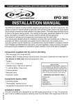
PLEASE LEAVE THIS MANUAL WITH THE OSO UNIT AFTER INSTALLATION
SOLARCYL
IM/SC2
INSTALLATION MANUAL
This cylinder is manufactured and approved in accordance with EN 12897:2006.
This manual gives detailed advice for installation and should be read carefully
prior to fitting any unvented unit.
This OSO cylinder must be installed by a competent person and be installed in
compliance with the OSO Installation and Maintenance Instructions, all current
legislation, codes of practice and regulations governing the installation of unvented
hot water cylinders in force at the date of installation.
Components supplied with the unit for site fitting
(See also page 2 for component list)
* Multibloc valve, includes pressure reducing valve, line strainer, balanced cold water take off,
(for shower or bidet only) check and expansion valve.
* Tundish
Health and Safety
* 1/2’’F x 15 x 15 tee piece
Manual Handling Operations Regulations 1992 defines
manual handling as: “any transporting or supporting of a
* Flexible hose
load (including the lifting, putting down, pushing, pulling,
carrying or moving thereof) by hand or bodily force”. The
* 3/4’’ x 22mm Elbow / Drain Cock
Regulations set no specific requirements such as weight
limits. However common sense still has to be used
* Blanking plug
based on an ergonomic approach for each individual.
* Motorised valve (indirect only)
DIMENSIONS AND WEIGHTS TABLE 1
* Expansion vessel.
PRODUCT REF.
197250300380
HEIGHT
1150140016002090
DIAMETER
580580580580
WEIGHT EMPTY 50545783
MAX WEIGHT FULL 241
297
339 454
COIL SURFACE AREA - M²
UPPER COIL
0,40,40,40,8
LOWER COIL 0,80,80,80,8
Components factory fitted
* Immersion heater(s)
* Thermostats / thermal cut-out
* Temperature and pressure relief valve.
142044-05
Installation details
The OSO unvented unit is designed for use with supply pressure up to 16 bar. For pressures
over 16 bar an additional pressure reducing valve must be fitted in the supply pipe to the unit.
-1-
General Layout Fig: 1
SOLARCYL TWIN COIL
Twin Coil Single Immersion Heater
KEY
1
1A
2
2A
3
4
5
6
7
7A
7B
7C
8
Return 3/4” BSP Boiler
Return 3/4” BSO Solar
Flow 3/4” BSP Boiler
Flow 3/4” BSP Solar
Pressure Reducing Valve Multibloc
Includes Item 4
Expansion valve
Temperature and Pressure
Relief Valve
Tundish
Immersion Heater
Immersion Heater Thermostat
Thermostat Boiler
Thermostat Solar
Cold Feed Tube
(Not supplied see Table 2)
SOLARCYL SINGLE COIL
Single Coil Twin Immersion Heater
Part No.
CUTAWAY
KEY
355013
(3.0 bar cartridge
REDC 355013)
510505
550853
219002
71259
80020
80030
80020
Part No.
9
10
11
13
14
15
16
17
18
19
20
21
Hot Water Outlet 3/4” BSP
Flexible Hose
Flexible Hose for Expansion Vessel
Elbow / Drain Cock
Cable Entry
Electrical Box
Tee Piece
Discharge Pipe (Not supplied)
Motorized Valve (Not Factory Fitted)
Sensor pockets ø 8 mm
T-piece for expansion vessel conn.
Expansion vessel
Size Lenght of tube (ø22) mm Exp. vessel pre charge
197
860
2,5 bar
250
1060
2,5 bar
300
1300
2,5 bar
380
1775
2,5 bar
202108
91911
250445
250006
92000
AX12, 19 or 24
TABLE 2
-2-
COLD WATER SUPPLY
1. To obtain the best performance from your OSO unvented system it is advisable to feed the unit
with an uninterrupted supply.
2. Before connecting to the multibloc, flush the cold supply pipework of all flux and debris.
3. Locate the water heater in a suitable position to facilitate the installation of the cold water supply,
discharge fittings and pipework. Also take into account access to the immersion heaters and the
commissioning valve.
4. Fit the combined male elbow drain cock to cold supply point (13), so that the compression fitting
is vertical.
5. Fit the blanking plug (12) to the secondary return fitting. If secondary return is to be used - see point 16.
6. Fit the female outlet of the tee piece to the temperature and pressure relief valve (5) with the
horizontal connection facing right at approx. 45°.
7. Fit the tundish (6) to the tee piece using a short length of 15mm copper tube.
8. Fit the length of copper tube 22mm specified in Table 2 to the cold feed elbow (see 4 above) to
include a T piece (20) for expansion vessel flexible hose.
9. Fit the pressure reducing valve (3) to the top of the copper tube (see 8 above), so that the black
knob is facing right.
10.Connect the flexible hose to the 1/2’’ outlet of the expansion valve (4) and the horizontal outlet
of the tee piece (see 6 above). Discard compression nut & ring.
11.If a balanced mains pressure cold water supply is required to a shower or bidet (over rim type
only), remove the blanking cap from the pressure reducing valve (3) and connect to the shower
or bidet cold supply. Using the balanced cold connection to feed bath taps can reduce the
flow available to the unvented cylinder. (Major shower manufacturers advise fitting a mini
expansion vessel in the pipework to accommodate thermal expansion and prevent
tightening of shower controls)
12.Connect the cold supply to the Multibloc (3).
13.Fit the expansion vessel to the wall close to the water heater using the enclosed mounting bracket.
Connect the expansion vessel hose to the T piece in the cold feed pipe to the cylinder. The expansion
vessel is supplied with the OSO unit, fit as shown on page 2.
Hot water supply
14.Connect the hot water supply pipe to the outlet (9). Ensure connection is water tight.
Secondary return (optional)
15.Connect secondary return if required to fitting according to diagram on page 16.
Discharge pipe
16. Connect the discharge pipe from the tundish (6). This must have a continuous fall and be fitted
in accordance with The Building Regulations (see page 16). The tundish should be installed away
from electrical devices.
Boiler Primaries - Primary flow & return and motorised valve
17.The boiler primary flow and return connections should be made to the upper coil connections
unit. The motorized valve can be connected to either the primary flow or return pipe. The primary flow
and return fittings are 3/4’’ BSP female. The valve has 22mm x copper connections. The direction of
primary flow in the boiler coil is bottom to top. The maximum operating temperature of the primary flow
would typically be 82°C.
18.For electrical connection of the motorised valve and immersion heater, please read Electrical
Installation Instructions. (Pages 7 - 11)
Solar Primaries
19.The Solar flow and return connections should be made to the lower coil connections.
Temperature control from the Solar circuit is achieved using a differential solar controller. This
controller must be wired in series through the thermal cut-out on the OSO thermostat (see figure
4 pages 9 & 11). If Solar Collectors are to be installed at a later date then connect the boiler primaries
to the lower coil. The driection of solar primary flow in the solar coil is top to bottom.
20.The solar circuit must be installed with a solar hydraulic station which must incorporate a pump and
non-return valves in both flow and return within the solar circuit. This system will prevent thermal
siphoning when the pump is not active.
-3-
21.Temperature sensors for the cylinder provided with the differential controller should be inserted
into the pockets provided (see pt 5 above).
22.There is no maximum primary temperature from the solar system and primary temperatures in excess
of 100°C are not unusual. All components on the solar circuit must be suitable for these higher
temperatures. Should the solar circuit be installed incorrectly, then all approvals and guarantees of the
cylinder are invalid.
COMMISSIONING
Filling up
1. Open a hot tap.
2. Open the cold water supply valve
3. when water flows from hot tap, close the tap
4. Allow the system to stabilize for 5 minutes
5. Open each hot water tap in turn to expel air from the system pipe work.
6. Check for leaks.
7. Manually operate Temperature and Pressure Relief Valve (5) to ensure free water flow through
discharge pipe. (Turn knob to left.)
Draining/flushing
1. Turn off mains supply.
2. Connect hose pipe to drain cock at base of cylinder.
3. Open hot tap. Open drain valve and open temperature & pressure relief valve.
4. Allow to drain. Follow commissioning instructions (above) to refill.
SAFETY AND MAINTENANCE
Safety Cut-out
1. The safety cut-out operates if:
a. Wiring is incorrect.
b. The immersion heater thermostat or cylinder thermostat fails.
c. Thermostat is set too high.
2. Remember before resetting the safety cut-out or altering the thermostat setting, isolate electrical
supply to the unit prior to removal of the electrical box lid.
3. Reduce thermostat setting and press the reset button. After adjustments are completed, ensure
the lid to the electrical box is replaced correctly and the retaining screw is fitted.
4. If still out of operation, contact installer.
RECOMMISSIONING INSTRUCTIONS
Cold or tepid water discharge from tundish - The tundish should be installed away from electrical devices.
1. Close cold water supply valve
2. Open a hot tap.
3. Repressurise the expansion vessel air charge to its set level.
4. Close hot tap
5. Open the cold water supply valve
Hot water discharge from tundish
This indicates a malfunction of a thermal cut-out, operating thermostat or the combined temperature
and pressure relief valve. Turn off the electrical supply to the immersion heater and also isolate an
indirect unit from the boiler. Contact the installer or competent engineer.
TABLE 3
Size Max. design
litres
pressure
197
8 bar
250
8 bar
300
8 bar
380
8 bar
Operating pressure Pressure drop primary heater Temp. / pressure
CW feed & coils
lower & upper
relief valve
cw in 2 bar, coils 2.5 / 6 lower 0,2 bar, upper 0,1 bar 90-95°C / 10 bar
cw in 2 bar, coils 2.5 / 6 lower 0,2 bar, upper 0,1 bar 90-95°C / 10 bar
cw in 2 bar, coils 2.5 / 6 lower 0,2 bar, upper 0,1 bar 90-95°C / 10 bar
cw in 2 bar, coils 2.5 / 6 lower 0,2 bar, upper 0,1 bar 90-95°C / 10 bar
-4-
Safety valve
Pressure / conn.
8 bar / 15mm - 1/2”
8 bar / 15mm - 1/2”
8 bar / 15mm - 1/2”
8 bar / 15mm - 1/2”
Exp. vessel
capacity
12 l.
19 l.
19 l.
24 l.
INSTALLATION AND SERVICING INSTRUCTIONS
Positioning the unit
The water heater should be fitted level on a hard surface with sufficient load strenght to take the
full weight of the cylinder (see table 1 page 1). Adjustable feet are fitted to ensure the unit can be
adjusted to a level position. There is no limitations regarding the fitting distance from walls etc., but
it is strongly recommended to ensure easy access to all pipe fittings etc. There should be at least 80
cm of free space in front of the water heater to ensure easy access for servicing and maintenance.
Protection from frost
If the water heater is in danger of being exposed to frost while not operating under electric power,
the unit must be drained to avoid damage. Make sure the electric power is turned off before draining,
otherwise the heating elements can be damaged and the warranty is void. Draining instructions, see
“Commissioning” on page 4.
Cold water inlet control (Multibloc) See Page 2 Items 3 - 4
This combination consists of a pressure reducing valve with integral strainer, check valve and
expansion valve with stainless steel seat. The pressure settings are set and locked in the factory and
are shown on the top of each valve. For optimum performance the following installation instructions
should be complied with.
Installation
1. Cold water supply to be 22mm nominal size.
2. Flush supply pipework before connection to remove all flux and debris prior to fitting the inlet
controls. Failure to do this may result in irreparable damage to the controls and will invalidate
the warranty.
3. The “MULTIBLOC” can be fitted in any orientation to suit the installation as long as it is fitted in
the correct flow direction. Check the flow arrows on the side of the body.
4. The expansion valve should be either horizontal or pointing downwards. If fitted upwards, debris
may be deposited on the seat and cause fouling of the seat when the valve operates. Check
direction of flow arrows.
5. The black plastic plugs in the body are pressure gauge connections to enable pressure
monitoring to be carried out, should the system develop a fault. It is recommended that these
be accessible (the pressure reducing valve has two - only one need be accessible).
6. Expansion relief drain pipework must be connected to a safe visible discharge point via a
tundish and the pipework must have a continuous fall.
7. The pressure reducing valve has two outlets, the second one is for a balanced cold water
supply, to a shower or a bidet (over rim type only, ascending spray type requires type AA,
AB or AD air gap). (Major shower manufacturers advise fitting a mini expansion vessel in
the balanced cold supply to accommodate thermal expansion and prevent tightening of
shower controls).
Using the balanced cold connection to feed bath taps can reduce the flow available to the
unvented cylinder. If not required the balanced cold supply is blanked off.
The Benchmark Log Book enclosed with the cylinder should be completed after commissioning
of the system and handed to the customer for future use.
TABLE 4
Size
litres
197
250
300
380
Weight empty
50
54
57
83
Weight Heat-up (mins)
Rating (kW)
full lower / upper coil lower / upper coil
241
37 / 30
16,1 / 10,8
297
41 / 41
17,6 / 11,0
339
49 / 51
17,4 / 10,8
454
62 / 46
17,8 / 16,4
Heat loss
kWh/24h
1,9
2,1
2,3
3,2
Primary
flow rate
15 l/min. - 80°C
15 l/min. - 80°C
15 l/min. - 80°C
15 l/min. - 80°C
Hot water capacity (l.)
lower / upper coil
195 / 108
233 / 147
277 / 193
350 / 238
Note: Temperature rise is from 15 to 60°C. Coil heating performance based on a primary flow rate of 15 l/min. at 80°C.
-5-
MAINTENANCE
It is recommended that annually a competent person
(a) Inspects and cleans the line strainer.
(b) Checks the operation of the expansion relief valve and temperature & pressure relief valve.
(c) Recommissions the cylinder in accordance with the instructions on page 4.
Corrosion resistance
Duplex stainless steel is naturally corrosion resistance to mains water supply. No specific maintenance is required to maintain this resistance. Please see guarantee terms for permissable water
content. Please note: OSO cylinders are not guaranteed for use with a private water supply.
The immersion heater can be removed to provide visual inspection access to the cylinder.
Pressure reducing valve
1. Isolate the cold water supply and open a
ground floor cold tap.
2. Unscrew the pressure reducing cartridge
3. Clean the filter mesh and the cartridge
under running water.
4. Replace cartridge ensuring that strainer is
correctly located and reassemble the unit.
Pressure Reducing Valve cartridge and
strainer Part No. REDC312100 - 3 Bar.
Expansion relief cartridge
1. Isolate the cold water supply and open a
ground floor cold tap.
2. Unscrew blue expansion relief headwork
from valve body.
3. Clean valve seat face and seating - do not
scratch or damage either seat face or seating.
4. Refit in reverse order. Do not overtighten
Expansion valve cartridge and seat Part
No. RELC 102201 8.0 Bar.
Complete Expansion Valve Part
No. PREL 102300 8.0 Bar.
SPARE PARTS
Expansion valve
(Cartridge and seat)
Part No. RELC 102201
8.0 Bar
Pressure reducing valve
Cartridge - Part No.
REDC 312100 - 3 bar
Expansion valve
Part No.
PREL 102300
8.0 Bar
Tundish
Install theTundish in a vertical position within a maximum of 600mm from the temperature and
Pressure Relief Valve drain connection. Ensure the expansion relief pipework discharges through the
tundish. Tundish pipework must be 22mm with a minimum vertical length of 300mm below tundish.
Maximum permitted length of 22mm pipework is 9m. Each bend or elbow is equivalent to 0.8m of
pipework.
All pipework must have continuous fall and discharge in a safe, visible position. If any doubt, refer to
Building Regulation G3.
-6-
ELECTRICAL INSTALLATION
Immersion heaters
SolarCyl Single coil is provided with twin immersion heaters. The upper immersion heater is
designed as an auxiliary heater to supplement the solar energy and will ensure the top section of
the water heater is fully heated.
All SolarCyl units are supplied with an immersion heater at low level. This immersion heater
is to allow full heating of the entire cylinder should it be required for cleansing purposes. The
lower immersion heater should not be in regular use as this will severely compromise the solar
efficiency of the cylinder.
Wiring instructions for the immersion heater is located on the reverse side of the lower lid. Follow
the wiring instructions connecting the live, neutral and earth as indicated. The electrical connection
to the immersion heater must conform to current IEE wiring regulations. The unit must be
permanently connected to the electrical supply through a double-pole linked switch with a
minimum break capacity of 13 amps. All internal wiring is factory mounted. Each immersion
heater has a working thermostat adjustable between 40°C - 70°C. A safety cut-out is also
incorporated within the thermostat and will operate at 85°C ± 3°C. Should this happen, press the
reset button.
Important: Before resetting the safety cut-out or altering the thermostat setting, isolate
electrical supply to the unit prior to removal of the lid. Ensure the lid to the electrical box
is replaced correctly and the retaining screw is fitted.
Indirect Units upper coil
Motorised valve
To comply with regulations governing the installation of indirect unvented cylinders, a motorised
valve must be fitted in the primary flow. Your OSO unit has been supplied with a two port
motorised valve, which will act as a positive energy cut-out should the safety cut-out operate.
The motorised valve will also control the temperature of the domestic stored water via the
cylinder thermostat, which is located in the upper electrical box. The unit should be installed on
an “S” or “Y” plan system. Cylinder temperature control can also be achieved via the solar
thermostat when the boiler is not operational.
Please follow the instructions carefully. All electrical connections must conform to current IEE
wiring regulations. The working thermostat is adjustable between 40°C - 70°C. A safety cut-out
is also incorporated within the thermostat and will operate at 85°C ± 3°C. Should the safety
cut-out be brought into operation, the motorised valve will operate and close down the primary
flow to the cylinder. To reset the safety cut-out and the motorised valve the reset button must be
pressed in (see fig.4 page 8).
Lower (Solar) coil
Heat sources to unvented hot water cylinders must be controlled by a thermal cut-out as well as
a thermostat. The OSO Solarcyl is supplied both with bosses for solar sensor pockets and the
pockets themselves.
The top half of the thermostats fitted to the cylinder is a thermal cut-out. The solar controller (not
supplied) and solar sensor point should be wired through the OSO thermal cut-out. See fig. 4
pages 8 & 10.
Please note that the direction of flow in the solar coil is reversed compared to the boiler coil. If
the cylinder is not being used for solar use, connect the boiler to the lower coil with the primary
flow in a bottom to top direction.
OSO Hotwater (UK) Limited can not be responsible if alternative wiring plans are used.
Important: Before resetting the safety cut-out or altering the thermostat setting isolate
electrical supply to the unit before removal of the lid.
-7-
The wiring plan shown is based on the use of a 10-way Junction Box (Honeywell Part no. 42002116-001).
Junction Box terminal 8 is switched live and, if needed, terminal 10 is pump live.
FIGURE 4
SOLAR
thermostat
SOLAR CONTROLLER WIRING
1
1
Safety
Cut-out
3
RESET
Differential
Solar
Controller
L
2
N
2
E
3
1
L
1
N
2
2
E
3
+
Electrical spare parts:
Immersion Heater
Immersion Heater Thermostat
Coil Thermostats
Reset
button
4
71259
80020
80030
-8-
-
Radiators/UFH
Automatic
bypass
Heat
source
Solar
Collector
Sensor
Pocket
-9-
The wiring plan shown is based on the use of a 10-way Junction Box (Honeywell Part no. 42002116-001).
Junction Box terminal 8 is switched live and, if needed, terminal 10 is pump live.
FIGURE 4
SOLAR
thermostat
SOLAR CONTROLLER WIRING
1
1
Safety
Cut-out
3
RESET
Differential
Solar
Controller
L
2
N
2
E
3
1
L
1
N
2
2
E
3
+
Electrical spare parts:
Immersion Heater
Immersion Heater Thermostat
Coil Thermostats
Reset
button
4
71259
80020
80030
-10-
-
Radiators/UFH
Automatic
bypass
Heat
source
Solar
Collector
Sensor
Pocket
-11-
1. Repressurize expansion vessel.
Follow recommissioning
instructions on page 4.
2. Switch off power to immersion
heater(s) and boiler supply to
the unit. When discharge has
stopped, check thermal
controls, replace it faulty.
Contact a competent person.
Reduced
expansion volume
Repressurize expansion vessel. Follow recommissioning
instructions on page 4.
NOTES:
_____________________________________________________________________________
_____________________________________________________________________________
_____________________________________________________________________________
_____________________________________________________________________________
_____________________________________________________________________________
_____________________________________________________________________________
_____________________________________________________________________________
_____________________________________________________________________________
_____________________________________________________________________________
_____________________________________________________________________________
_____________________________________________________________________________
_____________________________________________________________________________
_____________________________________________________________________________
_____________________________________________________________________________
_____________________________________________________________________________
_____________________________________________________________________________
_____________________________________________________________________________
_____________________________________________________________________________
-15-
ALTERNATIVE DISCHARGE
Downward discharges at low
FIGURE 4
level, i.e. up to 100mm above
external surfaces such as car
parks, hard standings, grassed
areas etc, are acceptable providing that where children may
play or otherwise come into
contact with discharges, a wire
cage or similar guard is positioned to prevent contact, whilst
maintaining visibility.
Discharge at high level, i.e.
into a metal hopper and metal
down pipe with the end of the
discharge pipe clearly visible
(tundish visible or not) or onto
a roof capable of withstanding
high temperature discharges of
water and 3m from any plastics guttering system that would collect such discharges (tundish visible).
Where a single pipe serves a number of discharges, such as in blocks of flats, the number served
should be limited to not more than 6 systems so that any installation discharging can be traced
reasonably easily. The single common discharge pipe should be at least one pipe size larger than
the largest individual discharge pipe to be connected. For further information contact your Building
Control Office or The British Board of Agrément.
SECONDARY RETURN
FIGURE 5
1. Secondary Return Fitting
2. Non Return Valve
3. Circulation Pump
4. Secondary Return Line
5. Balanced cold supply for showers or bidet only
HOTWATER UK Ltd.
All replacement parts must be supplied by OSO HOTWATER (UK) LIMITED.
To obtain the address of a local stockist contact:
OSO HOTWATER (UK) LTD.
E15 Marquis Court - Team Valley Trading Estate - Gateshead - Tyne&Wear, NE11 0RU
Phone: (0191) 482 0800 • Fax: (0191) 491 3655 • www.oso-hotwater.com
E-mail: [email protected] • [email protected] • [email protected]