1
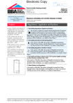
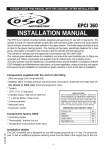
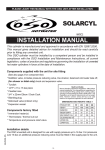
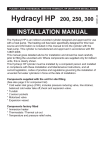
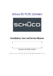
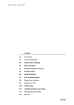
APPROVAL
INSPECTION
TESTING
CERTIFICATION
Fabdec Limited
Grange Road
Ellesmere
Shropshire SY12 9DG
Tel: 01691 627200 Fax: 01691 627222
TECHNICAL APPROVALS FOR CONSTRUCTION
Agrément Certificate
09/4701
e-mail: [email protected]
website: www.fabdec.com
Product Sheet 1
FABDEC UNVENTED HOT WATER STORAGE SYSTEMS
FABDEC DIRECT AND INDIRECT UNVENTED HOT WATER STORAGE SYSTEMS
WITH INTEGRAL EXPANSION (2 BAR)
This Agrément Certificate Product Sheet(1) relates to
Fabdec Direct and Indirect Unvented Hot Water Storage
Systems with Integral Expansion (2 bar), a range of
polyurethane insulated stainless steel storage vessels for
use with gas, electric or oil fired boilers on mains or
other suitable potable water supply pressures up to and
including 9 bar.
(1) Hereinafter referred to as ‘Certificate’.
CERTIFICATION INCLUDES:
• factors relating to compliance with Building
Regulations where applicable
• factors relating to additional non-regulatory
information where applicable
• independently verified technical specification
• assessment criteria and technical investigations
• design considerations
• installation guidance
• regular surveillance of production
• formal three-yearly review.
KEY FACTORS ASSESSED
Hot water storage and supply — the capacities of the systems range are comparable with conventional systems
(see section 6).
Safety — the system incorporates safety devices to safeguard the operation of the system (see section 7).
Watertightness — the storage cylinder remains watertight at pressures in excess of 1.5 times the design pressure
(see section 10).
Durability — the systems are manufactured from durable materials and conventional plumbing components and will
have a life equal to that expected of a vented system (see section 15).
The BBA has awarded this Certificate to the company named above for the systems described herein. These
systems have been assessed by the BBA as being fit for their intended use provided they are installed, used and
maintained as set out in this Certificate.
On behalf of the British Board of Agrément
Date of First issue: 3 May 2013
Brian Chamberlain
Greg Cooper
Originally certificated on 4 December 2009.
Head of Approvals — Engineering
Chief Executive
The BBA is a UKAS accredited certification body — Number 113. The schedule of the current scope of accreditation for product certification is
available in pdf format via the UKAS link on the BBA website at www.bbacerts.co.uk
Readers are advised to check the validity and latest issue number of this Agrément Certificate by either referring to the BBA website or contacting the BBA direct.
British Board of Agrément
Bucknalls Lane
Watford
Herts WD25 9BA
©2013
Page 1 of 15
tel: 01923 665300
fax: 01923 665301
e-mail: [email protected]
website: www.bbacerts.co.uk
Regulations
In the opinion of the BBA, Fabdec Direct and Indirect Unvented Hot Water Storage Systems with Integral Expansion
(2 bar), if installed, used and maintained in accordance with this Certificate, will meet or contribute to meeting the
relevant requirements of the following Building Regulations (the presence of a UK map indicates that the subject is
related to the Building Regulations in the region or regions of the UK depicted):
The Building Regulations 2010 (England and Wales) (as amended)
Requirement: G3
Hot water storage
Comment:
The systems incorporate suitable safety devices to meet the requirements of this Requirement. See sections 7
and 16 of this Certificate.
Requirement: L1A/L1B
Regulation
26
Conservation of fuel and power
CO2 emission rates for new buildings
Comment:
The systems have acceptable standing energy losses, have adequate temperature controls and are
supplied with detailed user instructions with maintenance requirements. See section 6 of this Certificate.
Regulation
7
Materials and workmanship
The systems are acceptable. See section 15 and the Installation part of this Certificate.
Comment:
The Building (Scotland) Regulations 2004 (as amended)
Regulation:
8(1)(2)
The systems comply with the requirements of this Regulation. See sections 14 and 15 and the Installation
part of this Certificate.
Comment:
Regulation:
Standard:
9
4.9
6.3
6.4
Insulation of pipes, ducts and vessels
The storage vessels have adequate insulation and can satisfy this Standard, with reference to clause
6.4.2(1)(2). See section 6 of this Certificate.
Comment:
Standard:
Heating system
The systems are fitted with a thermostat which meets the requirements of this Standard, with reference to
clauses 6.3.9(1) and 6.3.8(2). See section 6 of this Certificate.
Comment:
Standard:
Building standards applicable to construction
Danger from heat
The systems are constructed to prevent the temperature of the stored water at any time exceeding 100°C
and to provide adequate protection from malfunction of the system. The systems will satisfy this Standard,
with reference to clauses 4.9.1(1)(2), 4.9.2(1)(2), 4.9.3(1)(2) and 4.9.4(1)(2). See sections 7 and 16 of
this Certificate.
Comment:
Standard:
Fitness and durability of materials and workmanship
7.1(a)(b)
Statement of sustainability
The product can contribute to meeting the relevant requirements of Regulation 9, Standards 1 to 6 and
therefore will contribute to a construction meeting a bronze level of sustainability as defined in this Standard.
Comment:
(1) Technical Handbook (Domestic).
(2) Technical Handbook (Non-Domestic).
The Building Regulations (Northern Ireland) 2012
Regulation:
23(a)(i)(iii)(b)
Fitness of materials and workmanship
Comment:
Regulation:
Regulation:
39(a)(ii)(b)(c)
40
Conservation measures
Target carbon dioxide Emissions Rate
The systems are acceptable. See section 15 and the Installation part of this Certificate.
The systems comply with the domestic heating compliance guide and, therefore, will satisfy the requirement
of these Regulations. See section 6 of this Certificate.
Comment:
Regulation:
Comment:
88
Unvented hot water storage systems
The systems incorporate suitable safety devices to meet the requirements of this Regulation. See sections 7
and 16 of this Certificate.
The Health and Safety at Work etc Act 1974 and the Health and Safety at Work (Northern Ireland) Order 1978
In buildings subject to this Act and Order, regular maintenance is a requirement (See section 14 of this Certificate).
Water Supply (Water Fittings) Regulations 1999 England and Wales, Water Byelaws 2000, Scotland and the
Water Regulations, Northern Ireland
England and Wales
In the opinion of the BBA, Fabdec Unvented Hot Water Storage Systems satisfy the requirements of the water
Regulations if used and installed in accordance with this Certificate.
Scotland
In the opinion of the BBA, Fabdec Unvented Hot Water Storage Systems satisfy the requirements of the water Byelaws
if used and installed in accordance with this Certificate.
Page 2 of 15
Northern Ireland
In the opinion of the BBA, Fabdec Unvented Hot Water Storage Systems satisfy the requirements of the Water
Regulations if used and installed in accordance with this Certificate.
The Electrical Equipment (Safety) Regulations 1994 and the Electromagnetic Compatibility Regulations 2005
These Regulations implement the Low Voltage Directive 73/23/EEC (as amended by the CE Marking Directive
93/68/EEC) and the Electromagnetic Compatibility Directive 89/336/EEC and require manufacturers to carry
out assessment of their products against the criteria given in the Directives. Declarations of Conformity have been
provided by Fabdec Limited. The BBA has not assessed the product for compliance with these Directives.
Construction (Design and Management) Regulations 2007
Construction (Design and Management) Regulations (Northern Ireland) 2007
Information in this Certificate may assist the client, CDM co-ordinator, designer and contractors to address their
obligations under these Regulations.
See section:
3 Delivery and site handling (3.3) 7 Safety, 14 Maintenance and 18 Procedure of this Certificate.
Technical Specification
1 Description
1.1 The Fabdec Direct and Indirect Unvented Hot Water Storage Systems with Integral Expansion (2 bar) are for use
in domestic, commercial and public buildings for connection to domestic hot and cold water services to BS 6700 :
2009. Each system comprises the components shown in Figure 1. The storage capacities and main dimensions are
listed in Table 1.
1.2 The systems incorporate an internal expansion facility which, after commissioning, utilises trapped air at the top of
the storage cylinder to accommodate expansion of the heated water (see Figure 2).
1.3 Each system generally comprises a stainless steel storage cylinder complete with one or two immersion heaters
(depending on the model). All models are free-standing and connect to a cold feed supply as indicated in Table 1.
Table 1 Storage capacities and dimensions
Characteristic
Cylinder capacity (litres)
70
115
135
155
195
250
295
67
105
123
143
176
212
249
579
452
645
574
871
452
958
574
999
452
1086
574
1156
452
1243
574
1398
452
1485
574
1666
452
1753
574
1942
452
2029
574
424
634
726
839
1013
1207
1405
283
365
401
445
513
587
665
29
110
32
113
35
163
40
188
48
222
55
267
65
321
coil surface area (m2) (indirect only)
0.54
0.54
0.54
0.75
0.75
0.75
0.75
coil performance (kW) (indirect only)
10.5
10.5
10.5
20
20
20
20
—
381
494
626
838
1066
1302
Capacity at system pressure (litres)
Cylinder size (mm)
height
diameter
overall height
overall diameter
Temperature relief valve
height above floor (mm)
Dip tube overall length (mm)
Weight of cylinder (kg)
empty
full (maximum)
Upper immersion heater height above floor (mm)
(Direct only)
Page 3 of 15
Figure 1 General layout
direct system
7
1
4
2
6
5
14
3
8
6
15
9
see cold water
control set (below)
indirect system
7
1
4
2
5
14
12
10
3
13
9
6
8
11
15
Page 4 of 15
Figure 1 General layout (continued)
Schrader
valve
shut-off
valve
non-return
valve
pressure reducing
reducing valve set
at 2 bar
6 bar
expansion
valve
mains in
to water
heater
Cold water control set
1 Storage cylinder manufactured from stainless steel grade 1.4362
to EN 10088-3 : 2005
2 Insulation, CFC free polyurethane foam with a minimum thickness of 60 mm
3 Cold water control set with 22 mm connection to BS EN 1254-2 : 1998
4 Combined temperature and pressure relief valve. The valve has a set temperature
of 90°C and a pressure of 7 bar. Factory fitted
5 Tundish incorporating 15 mm inlet and 22 mm outlet compression connections
6 Immersion heater to BS EN 60335-2-73 :2003 wired to a thermostat and
non-self-resetting thermal cut-out. Thermostat set to a temperature of 60°C and the
cut-out is designed to operate when the stored water reaches 85°C
7 Hot water draw-off connection — 22 mm diameter
8 Drain valve (not supplied) to be fitted by the installer
9 Cold supply connection — 22 mm pipe
10 Primary flow connection — 22 mm pipe
11 Primary return connection — 22 mm pipe
12 Motorised valve 22 mm diameter compression connections
13 Combined thermostat and non-self-resetting thermal cut-out. Thermostat set to a
temperature of 60°C and the cut-out is designed to operate when the stored
water reaches 85°.
14 Discharge pipe
15 Cold feed isolating valve (not supplied).
NB Items 3, 5 and 12 are supplied separately for fitting by a competent person.
Figure 2 Expansion system – integral expansion system (2 bar system)
operating cycle
system commissioning
stage 1
stage 2
stage 3
air
water
cold feed open
hot tap open
when water comes
out of hot valve
open TPRV close
feed valve open TPRV
water cold 30%
pressure = 0 bar
volume of air = 30%
volume of water = 70%
close hot tap and TPRV tap
connect air pump to cylinder
valve open
shut off valve pump air to
achieve water cold
pressure = 0.7 bar
volume of air = 30%
volume of water = 80%
close shut off valve
cylinder at 1 bar:
cold feed open
hot tap closed
water cold
pressure = 1 bar
volume of air = 25%
volume of water = 75%
cylinder at cold supply
pressure:
cold feed open
hot tap closed
water cold
max pressure 2 bar
volume of air = 17%
volume of water = 83%
water heated:
cold feed open
hot tap closed
water heated
cylinder air bubble
compresses
pressure <3.5 bar
volume of air = 15%
volume of water = 85%
hot water drawn off to
stage 1 level:
cold feed open
hot tap open
water level drops to
stage 1 level, no cold
water fed into cylinder
water hot
pressure <2 bar
volume of air = 17%
volume of water = 83%
1.4 The cylinders are insulated with polyurethane (PU). The cylinders have an external casing of coated steel.
1.5 For safety, the systems include factory-fitted devices; a thermostat, thermal cut-out and the combined temperature
and pressure relief valve. Other components are supplied separately for fitting on site (see Figure 1 and section 2.1) by
a competent person (see section 16).
Components
1.6 The components that are required for use with the system are either as factory-fitted or supplied separately for
fitting by the installer and listed in Table 2.
Page 5 of 15
Table 2 Components
Component(1)
Manufacturer/supplier
and component number
Setting
Size
Altechnic pressure reducing valve
2 bar
22 mm
Altechnic expansion valve
6 bar
15 mm
Combined temperature and pressure relief valve
Altechnic
90°C/7 bar
15 mm
Tundish
Altechnic
—
15 mm/22 mm
Cotherm Type ELE-14-IN-800-FAB
—
1¾” BSP
Cotherm Type TUS 0228
77° to 83°C
—
Combined cold water control set(2)
Immersion heater assembly
Direct non-self-resetting thermal cut-out
Direct thermostat
Cotherm Type TUS 0228
10° to 70°C
—
Indirect non-self-resetting
thermal cut-out
Cotherm Type GTLHR 038
75° to 85°C
—
Indirect thermostat
Cotherm Type GTLH 3101
10° to 70°C
—
Indirect thermostat and non-self-resetting
thermal cut-out
I STAT 805.XR308.03A
25° to 65°C
74° to 86°C
—
—
Motorised valve(3)
Reliance Zone 250105
Sunvic SZMV 2305
—
—
(1) The replacement or servicing of any components must be carried out, using the Fabdec Excelsior Installation Manual, by a competent person (see section
16), or by Fabdec Limited under their responsibility as the product manufacturer, including that required by their warranty, using components supplied by
Fabdec Limited.
(2) Combined cold water control set — incorporating pressure reducing valve set at 2 bar, expansion valve set at 6 bar, check valve, balanced cold
connection and commissioning connection.
(3) It is essential on indirectly heated systems that the motorised valve supplied with the system is installed and is not substituted by any other motorised valve
which may exist and be in service at the site of installation, eg a motorised valve installed in a central heating circuit.
2 Manufacture
2.1 Factory production control is exercised during the manufacture and assembly of each of the components
including; visual examination, dimensional checks and performance tests. Each storage cylinder is pressure tested and
examined for leaks during manufacture and prior to dispatch.
2.2 As part of the assessment and ongoing surveillance of product quality, the BBA has:
• agreed with the manufacturer the quality control procedures and product testing to be undertaken
• assessed and agreed the quality control operated over batches of incoming materials
• monitored the production process and verified that it is in accordance with the documented process
• evaluated the process for management of nonconformities
• checked that equipment has been properly tested and calibrated
• undertaken to carry out the above measures on a regular basis through a surveillance process, to verify that the
specifications and quality control operated by the manufacturer are being maintained.
3 Delivery and site handling
3.1 A complete system(1) is delivered to site protected by packaging. The following items (see also section 1.6) are
supplied separately with each storage cylinder for fitting on site by a competent person, all other components(1) are
factory fitted:
• combined pressure reducing valve and line strainer, fitted with an air inlet valve
• combined expansion and check valve
• motorised valve (indirect systems only)
• tundish.
(1) A drain valve will be required but is not supplied with a system.
3.2 When a system is required to be stored, it must be stored in a dry environment and protected from damage.
3.3 The system must be carefully handled and kept in the packaging until required for siting in position. The weight of
each system empty and full is stated in Table 1 and on the label attached to each system.
Labelling/marking
3.4 Each system carries a label (or labels) bearing the information set out in Table 3 and is supplied with a
comprehensive installation/user manual.
Page 6 of 15
Table 3 Labels
General
1
2
3
4
5
6
7
The BBA identification mark incorporating the number of this Certificate.
The system uses BEAB (British Electrotechnical Approvals Board) or CE-approved electrical controls.
UKWFBS (United Kingdom Water Fittings Byelaws Scheme) list number.
Manufacturer’s name.
Product code number.
Order number and year of manufacture.
The system is an unvented system.
Design
1
2
3
4
5
Maximum water supply pressure (bar).
Operating pressure (bar).
Expansion valve setting (bar).
Storage capacity (litres).
Weight of system — full (kg).
Safety warning/conditions
1 Installation to be carried out only by a competent person.
2 The removal/replacement of any component to be carried out only by a competent person using components supplied by Fabdec in
accordance with their instructions.
3 Any malfunction of the system, such as that resulting in discharge of water to the tundish from the combined temperature and pressure relief
valve, to be reported to a competent person, after switching off the heat source and prior to any further use of the system.
4 The installation of the system is subject to approval under the Building Regulations, Water Byelaws and Regulations, the Health and Safety at
Work etc Act 1974 (where appropriate) and the Health and Safety at Work (Northern Ireland) Order 1978 (where appropriate).
5 If water discharges from the expansion valve, the system must be recommissioned in accordance with the manufacturer’s instructions.
Installer(1) details
1 Space for:
(a) Name
(b) Address
(c) Telephone number
(d) Completion date
(e) Registration No ....
2 A declaration that installation has been in accordance with BBA Certificate ../.... with space for signature of the installer(1).
CE Marking
1 The system complies with the Low Voltage Directive 73/23/EEC.
2 The system when installed correctly will comply with the Electromagnetic Compatibility Directive 89/336/EEC.
3 CE Marking applied to these products by the manufacturer relates only to the Low Voltage and Electromagnetic Compatibility Directives. In the
opinion of the BBA, the application of CE Marking does not infer compliance with the requirements of the applicable Building Regulations.
(1) The installer must meet the definition of a competent person as defined in section 14.2.
Assessment and Technical Investigations
The following is a summary of the assessment and technical investigations carried out on Fabdec Direct and Indirect
Unvented Hot Water Storage Systems with Integral Expansion (2 bar).
Design Considerations
4 General
4.1 Fabdec Direct and Indirect Unvented Hot Water Storage Systems with Integral Expansion (2 Bar) have been
assessed in accordance with MOAT No 38 : 1986 or BS EN 12897 : 2006. When used with gas, electric or oil
fired boilers in accordance with this Certificate, the systems will perform in a safe and satisfactory manner.
4.2 The hot water system capacity, should be selected in accordance with the recommendations of BS 6700 : 2009,
to meet the demands required from the installation.
4.3 The systems operate at a nominal pressure of 2 bar and are for use with mains or other suitable potable water
supply pressures up to and including 9 bar.
4.4 For indirect heating systems, the primary circuit pipework should be designed in accordance with BS 6700 :
2009 and BS 5449 : 1990. Particular consideration should be given to the inclusion of a primary circuit by-pass
to prevent excessive pressure on the motorised valve and also safeguard against ‘nuisance tripping’ of the non-selfresetting thermal cut-out.
4.5 The pressure and flow available from the water mains should be obtained from the local water undertaker or by
testing existing supplies to establish the likely performance of the system at peak periods. The water supply should be
capable of maintaining a minimum cylinder pressure of 0.5 bar during draw-off. To maintain this dynamic pressure and
adequate availability of hot water to each draw-off point, it is recommended that when the static pressure is less than
2 bar, at least 1 metre of 15 mm diameter pipe be incorporated in the pipe run to each draw-off point.
Page 7 of 15
4.6 It is essential, for reasons of safety and performance, that installation of a system is undertaken only by a
competent person working in accordance with this Certificate.
5 Practicability of installation
The systems are designed to be installed by a competent person (see section 16), experienced with water storage
systems.
6 Hot water storage and supply
Hot water storage
6.1 The capacities of the systems range are comparable with conventional systems (see Table 1).
Flow rates
6.2 The flow rates achieved at the hot water draw-off point will depend on all the normal factors, including the layout
of the pipework from the tap to the cylinder, the cold water supply pressure and the flow rate available at the supply to
the system.
6.3 For design purposes, the graphs in Figure 3 show the relationship between:
• flow available,
• mains supply pressure, and
• the maximum hot water flow rate out of the system(1).
(1) Flow characteristics shown in the graphs reflect the worst combination of cold water control components that may be installed (see section 1.6).
Figure 3 Flow rates (2 bar pressure reducing valve)
70
8 bar
60
4 bar
flow out (l·min⫺1) of the system
50
40
2 bar
2, 4 and 8 bar mains
pressure supplied
30
20
10
0
0
10
20
30
40
50
60
70
80
90
100
110
120
⫺1
flow available (l·min ) at entry to the system
Heat-up, re-heating and hot water draw-off temperature
6.4 The heat-up and re-heat times are comparable with conventional systems of a similar size supplying hot water.
Page 8 of 15
6.5 Tests by the BBA on both Indirect and Direct systems to determine heat-up time and draw-off volumes and flow
rate values were carried out and the results are given in Tables 4 and 5. Slight variations in the results occur with
changes in the water mains supply pressure and draw off rates.
These results show:
• Direct Systems (see Table 4), the immersion heater(s) will heat the stored water from 15°C to 60°C in a time given
in columns C and F.
• Indirect Systems (see Table 5), the coil heat exchanger with a primary flow of 15 litres per minute of hot water at
a temperature of 80°C ± 2°C, or the immersion heater, will heat the stored water from a temperature of 15°C to
60°C in a time given in columns C and F.
Table 4 Heat-up and hot water draw-off performance — Direct system
System
reference
and nominal
capacity (l)
A
Draw-off
flow rate
B
Lower immersion
Heat-up
time(1)
(minutes)
Upper immersion
% draw-off within 20°C
of set temperature
(litres)
(%)
C
D
E
Heat-up
time(1)
(minutes)
Volume heated
(litres)
Hot water draw-off
(litres min–1)
Volume heated (litres)
F
G
H
70
9
68
52
74
–
–
–
115
15
111
87
76
64
60
51
135
15
130
102
76
63
59
49
155
15
160
121
78
66
59
47
195
15
190
149
76
63
58
43
250
30
230
206
82
63
58
58
295
30
272
243
82
62
57
57
(1) Immersion heaters all rated 3 kW at 240 Watts
Table 5 Heat-up and hot water draw-off performance — Indirect system
System
Draw-off flow
reference
rate
and nominal
capacity (l)
A
Indirect heating
Heat-up
time(1)
(minutes)
Direct heating
% draw-off within 20°C
of set temperature
(litres)
(%)
B
C
D
E
Heat-up
time(1)
(minutes)
% draw-off within 20°C
of set temperature
(litres)
(%)
F
G
H
70
9
14
53
75
68
52
74
115
15
21
90
78
111
87
76
135
15
25
107
79
130
102
76
155
15
25
126
81
160
121
78
195
15
28
154
79
190
149
76
250
30
33
209
84
230
206
82
295
30
39
246
83
272
243
82
(1) Immersion heaters all rated 3 kW at 240 Watts
Note: Primary flow rate of 15 litres per minute
6.6 The amount of water that can be drawn-off within 20°C of the set temperature (ie above 40°C for a set
temperature of 60°C) is shown in columns D and G. The quantity of hot water that can be extracted above 40°C
depends on the draw off flow rates indicated in column B.
Temperature control
6.7 The indirect thermostat is fitted to the system and connected via the wiring loom to the motorised valve and
provides adequate control of the stored water. The direct thermostat wired to the immersion heater is satisfactory for
controlling the temperature of the stored water when this form of heating is used.
Pressure control
6.8 The pressure control valve is satisfactory for controlling the pressure of the water supplied from the water mains
or other suitable potable supply. However, during the heat-up period from cold to 60°C, the water expands and
compresses the air gap at the top of the cylinder expansion vessel causing an increase in pressure to a maximum of
3.5 bar (see Figure 2). Under failure conditions, the expansion valve ensures the pressure will not exceed 6 bar. Each
storage cylinder is factory tested to 9.9 bar.
Page 9 of 15
Insulation
6.9 A systems provided with adequate insulation to satisfactorily limit the energy loss from the stored water and meets
the requirements described in the Building Regulations:
England and Wales — Approved Documents L1A, Sections 4.18 to 4.24 and L1B, Sections 4.24 to 4.29
Scotland — Mandatory Standard 6.4.
Northern Ireland — Technical Booklet F1, Sections 2.36 and 2.38
6.10 The heat loss of each system while maintaining the temperature of the stored water at 65°C is shown in Table 6.
Table 6 Standing energy losses(1)
System ref
Energy loss(2) (kWh/24 h)
70
115
135
155
195
250
295
1.16
1.45
1.58
1.70
1.90
2.11
2.33
(1) See section 6.5.
(2) These figures relate to a 45°C differential between the stored water
and ambient temperature.
Connections
6.11 Each system is designed to be connected to copper tube conforming to BS EN 1057 : 2006, Tables X, Y and
Z, using conventional plumbing fittings (see Table 1 for details of connection sizes and threads). The connections are of
adequate size.
7 Safety
Excessive temperature — Prevention of explosion — Safe discharge of hot water
The safety devices provided to ensure that the temperature of the stored water will not exceed 100°C/90°C,
and safeguard the operation of the system, are:
For the indirect coil heat exchanger
• the combined temperature and pressure relief valve, and
• the indirect non-self-resetting thermal cut-out wired to the motorised valve.
For the direct immersion heater
• the combined temperature and pressure relief valve, and
• the direct non-self-resetting thermal cut-out fitted to the system and wired to the immersion heater.
7.2 Each system has a safety warning label attached to the storage cylinder, bearing an explanation of the action to
be taken in the case of any malfunction of the system. It is essential that these instructions are followed.
7.3 Each system has adequate provision for safe disposal of discharges to a tundish from the combined temperature
and pressure relief valve [see also section 17(2)].
Physical contact
7.4 The surfaces of the storage cylinder are protected by the insulation. In normal use the temperatures of the surfaces
of the various parts of the system are comparable with those in a conventional vented hot water storage system.
Strength and stability
7.5 Each system has adequate resistance to internal pressures and the vacuum relief valve is effective in preventing
reduced pressure within the system.
7.6 Each system’s pressure control devices will ensure that the operating pressure will be controlled to a nominal 2.1
bar, and that the design pressure of 6 bar is not exceeded. Each storage cylinder has been satisfactorily pressure
tested to 1.5 times the design pressure, ie 9 bar.
7.7 The weight of a system is stated on the label attached (see also Table 1); the support arrangements appropriate to
a conventional system apply.
7.8 Care must be taken to avoid damage to the system during handling and installation.
Electrical safety
7.9 The indirect thermostat, non-self-resetting thermal cut-out and motorised valve, and the direct thermostat and nonself-resetting thermal cut-out are approved by BEAB to BS EN 60335-2.73 : 2003. To ensure safety, it is essential that
the electrical wiring is carried out in accordance with BS 7671 : 2008.
Page 10 of 15
8 Properties in relation to fire
8.1 Care should be exercised when installing a system to avoid sources of ignition, such as plumber’s blowlamp, to
prevent toxic fumes emitting from the polyurethane foam insulation. The material is not readily combustible and any
flaming and fume emission will stop when the source of ignition is removed.
8.2 In service, normally the cylinder will be enclosed and risk of ignition will be minimal. During installation care
should be exercised when using a blowlamp to make soldered joints on pipework adjacent to the cylinder. Installation
does not require soldered joints to be made direct to the system.
9 Effect on water quality and prevention of waste of water
The systems are listed by the Water Regulations Accreditation Scheme (WRAS).
10 Watertightness
The storage cylinder remains watertight at pressures in excess of 1.5 times the design pressure, ie factory tested to 9 bar.
11 Noise
The systems are quiet in normal operation, the flow of water being via conventional water pipe fittings, and compares
favourably with a vented hot water storage system.
12 Physiological effects
The insulation material will not encourage vermin or bacteria and is not susceptible to damage from moisture.
13 Site checks
On site the following should be checked:
By the Client
(1) The installer is a competent person — by reference to his/her identity card.
(2) The system being installed is BBA Certificated — reference to the label.
(3) That the installation complies with the BBA Certificate — by reference to the installer’s signature on the label
attached to the cylinder.
By the Building Control Officer, Building Standards Surveyors or Approved Inspector
(1) 1, 2 and 3 (as above).
(2) The combined temperature and pressure relief valve, thermostats, non-self-resetting thermal cut-outs, motorised valve
and the immersion heater(s) are as described in the Certificate.
(3) The tundish and discharge pipework are correctly located and fitted.
14 Maintenance
14.1 It is recommended that, annually, a competent person:
• inspects and cleans the line strainer
• recommissions the system in accordance with the manufacturer’s instructions (see section 19).
14.2 The replacement or servicing of components must be carried out by a competent person, using the Fabdec
installation instruction leaflet, or by the Certificate holder under their responsibility as the product manufacturer,
including that required by their warranty, using components supplied by the Certificate holder.
14.3 The system may be drained using the drain valve (not supplied).
14.4 When the systems are used in buildings subject to the Health and Safety at Work etc Act 1974, an inspection
of the system must be carried out every six months.
15 Durability
The systems are manufactured from durable materials and conventional plumbing components and will have a
life equal to that expected of a vented system. It may be necessary to replace some of the system components,
for example, the immersion heater, thermostat (see sections 1.6 and 14.2).
Installation
16 The installer
16.1 It is essential, for reasons of safety and performance, that the installation, commissioning and maintenance of a
system is carried out by a person with suitable training and practical experience. However, the assessment of training
arrangements and continuing competence of installers falls outside the scope of this Certificate.
Page 11 of 15
16.2 It is the view of Communities and Local Government and stated in Approved Document G3, that, to meet
the requirements of the Building Regulations (England and Wales), concerned with unvented hot water storage
systems with a storage vessel of not more than 500 litres capacity and power input not exceeding 45 kW,
installations should be undertaken by a competent person, defined as ‘one holding a current Registered Operative Skills
Certification Card for the installation of unvented domestic hot water storage systems’.
16.3 In Scotland, it is the requirement of Mandatory Standard 4.9, clauses 4.9.1(1)(2) and 4.9.2(1)(2), for
compliance with Regulation 9 of the Building (Scotland) Regulations 2004 (as amended), that installations should
meet the recommendations of BS EN 12897 : 2006, BS 6700 : 2009 as appropriate or be the subject of an
approval by a notified body and incorporate the safety devices outlined in clause 4.9.2(1)(2), and carried out by a
person with appropriate training and practical experience, such as one with current membership of a recognised
professional body, eg one administered by:
• the Scottish and Northern Ireland Plumbing Employers’ Federation (SNIPEF)
• Construction Industry Training Board (CITB)
• an equivalent body.
(1) Technical Handbook (Domestic).
(2) Technical Handbook (Non-Domestic).
•
•
•
•
16.4 In Northern Ireland, Technical Booklet P, Section 1.4 states that an unvented hot water storage system
used in a building, be designed, constructed and installed in accordance with the relevant provisions. Installers
must hold a current Registered Operative Identity Card issued by:
the Association of Installers of Unvented Hot Water Storage Systems (Scotland and Northern Ireland)
the Institute of Plumbing
the CITB; or
an equivalent body.
17 Conditions
The following conditions abstracted from the manufacturer’s instructions must be observed:
(1) Each system must be connected to a water supply with a pressure not exceeding 12 bar and of a quality supplied
by a water undertaker under the Water Byelaws and Water Regulations, as appropriate.
(2) The combined temperature and pressure relief valve tundish must be in a clearly visible position within 500 mm
of the cylinder and in the same compartment as the cylinder. The discharge pipe to and from the tundish must be
of metal and laid to fall. It must terminate at a visible safe place, such as a gully, where there is no risk of contact
with the hot water by persons in or about the building. Further details are given in the BBA Information No 33 :
1989 Unvented Hot Water Storage Systems — Hot Water Discharges from Safety Devices. BBA Requirements
and Guidance and the Building Regulations:
England and Wales — Approved Document G3
Scotland — Mandatory Standard 4.9, clause 4.9.3.
(3) A system is installed in locations similar to those for storage cylinders used in a conventional vented system or in
other locations advantageous to the building designer (see Table 1 for load weight of the system when ‘full’). It is
important to ensure there is adequate clearance for the removal of the immersion heater (see Table 1).
(4) Electrical wiring must be carried out in accordance with the IEE Wiring Regulations. The immersion heater circuit
must be protected by a suitably rated fuse, eg 13 A, and an isolating switch with double pole disconnection.
18 Procedure
Summary of installation procedure
18.1 The storage cylinder is located in position (see the Fabdec installation instruction leaflet) and the plumbing
connections(1) made to the inlet and outlet pipes in the same manner as for a conventional storage cylinder, except that
the water supply pipe is taken directly from the mains or other suitable potable supply, via the line strainer and cold
water control valves (ensuring the arrow markings on the components are pointing downstream) to the cold water inlet
of the storage cylinder (see Figure 1). Where balanced pressures are required, the cold water take-off is provided on
the pressure reducing valve assembly (see Figure 1), using components supplied by the Certificate holder.
(1) As the drain valve is not supplied with the system, it should be sourced independently and fitted appropriately between the cold water inlet and
the non-return valve.
18.2 The discharge pipe is connected to and from the tundish to a safe and visible termination point [see section 17(2)].
The air gap at the tundish must remain clear.
18.3 The appropriate electrical connections are made.
19 Commissioning
19.1 The system is filled with water in the sequences set out in the Fabdec installation and Operating Instructions.
Page 12 of 15
Integral expansion system
19.2 When commissioning instructions are followed, an air gap at the top of the storage cylinder is formed (see
Figure 2). It is important to ensure that the air gap is formed properly, by adopting the following procedure(1):
(1) Before the mains supply to the cylinder is turned on, a hot water tap should be opened preferably on the same
floor or on the floor below where the cylinder is located. All other hot water taps must be closed.
(2) The supply to the cylinder is turned on until water runs from the open hot water tap.
(3) The supply to the cylinder is turned off.
(4) When the water has stopped running from the open hot water draw off tap, the temperature and pressure relief
valve is operated until water stops flowing.
(5) The hot water tap and temperature and pressure relief valve are closed.
(6) An air pump is connected to the Schrader valve, located on the pressure reducing water inlet valve (see Figure 1).
(7) The Schrader valve shut-off valve is opened.
(8) Air is pumped into the unit via the Schrader valve until a pressure of 0.7 bar is reached.
(9) The shut-off valve is closed and the pump removed.
(10) The mains supply is reopened and the cylinder brought up to working pressure.
(11) To slowly release trapped air, the nearest hot water tap to the cylinder is gradually opened.
(12) To ensure all air is expelled from the system the remaining taps are opened in turn.
(1) Should the air gap be lost during use, this procedure should be used to reinstate it.
19.3 The system is checked for watertightness. The combined temperature and pressure relief valve is manually
operated to ensure water discharge from the valve runs freely through the tundish to the discharge point. The valve
is visually checked to ensure that it re-seats satisfactorily. Heat is applied to the system and allowed to reach normal
working temperature. The operation of the indirect and direct thermostats and motorised valve is checked and an
examination carried out to ensure that no water has discharged from the combined temperature and pressure relief
valve during the heat-up.
19.4 On completion of the commissioning process the competent person completes the label attached to the system,
stating that the installation complies with the Certificate (see section 3.4).
Technical Investigations
20 Tests
20.1 Tests were carried out in accordance with MOAT No 38 : 1986 to determine:
• capacity of storage cylinder
• dimensional accuracy
• mean supply temperature
• outlet flow rate at various supply flow rates and pressures
• time taken to heat to 60°C
• re-heat time to 60°C
• standing energy loss (adequacy of insulation)
• watertightness
• resistance of the storage cylinder and expansion vessel to an internal hydrostatic pressure of 1.5 times the design
pressure = 9 bar
• resistance to partial vacuum of 0.1 bar absolute
• flow capacity of the tundish and discharge pipework.
20.2 Other tests were carried out to determine:
• variations of storage capacities with variations in supply pressure
• satisfactory performance of the integral expansion system.
20.3 Tests were carried out to confirm satisfactory operation of the following components when fitted in a system:
• cold water control valves, to include:
— pressure control valve
— check valve
— expansion valve
• combined temperature and pressure relief valve
• indirect cylinder thermostat and non-self-resetting thermal cut-out
• motorised valve
Page 13 of 15
20.4 An examination was made of existing data in relation to the performance requirements of the relevant British
Standards, to determine the suitability and performance of:
• cold water control valves, to include:
— pressure control valve to BS 6283-4 : 2007
— check valve to BS EN 13959 : 2006
— expansion valve to BS EN 1491 : 2000
— line strainer
•
•
•
•
•
combined temperature and pressure relief valve to BS EN 1490 : 2000
immersion heater to BS EN 60335-2.73 : 2003
non-self-resetting thermal cut-out to BS EN 60730-2.15 : 1996
indirect cylinder thermostat and non-self-resetting thermal cut-out to BS EN 60730-2.15 : 1996
motorised valve to EN 607302.15 : 1996.
20.5 An examination was made of existing data relating to:
• adequacy of installation instructions
• practicability of installation by the competent person
• electrical safety
• effect on water quality and prevention of waste of water
• properties in relation to fire
• practicability and adequacy of maintenance requirements
• durability of materials used.
20.6 An evaluation of tests in accordance with MOAT No 38 : 1986.
21 Investigations
The manufacturing and assembly process was examined, including the methods adopted for quality control, and details
were obtained of the quality and composition of materials used.
Bibliography
BS 2879 : 1980 Specification for draining taps (screw-down pattern)
BS 5449 : 1990 Specification for forced circulation hot water central heating systems for domestic premises
BS 6144 : 1990 Specification for expansion vessels using an internal diaphragm, for unvented hot water supply
systems
BS 6283-4 : 2007 Safety and control devices for use in hot water systems — Specification for droptight pressure
reducing valves of nominal size up to and including DN 50 for supply pressures up to and including 12 bar
BS 6700 : 2009 Specification for design, installation, testing and maintenance of services supplying water for
domestic use within buildings and their curtilages
BS 7671 : 2008 Requirements for electrical installations
BS EN 1057 : 2006 Copper and copper alloys — Seamless, round copper tubes for water and gas in sanitary and
heating applications
BS EN 1254-2 : 1998 Copper and copper alloys — Plumbing fittings — Fittings with compression ends for use with
copper tubes
BS EN 1490 : 2000 Building valves — Combined temperature and pressure relief valves — Tests and requirements
BS EN 1491 : 2000 Building valves — Expansion valves — Tests and requirements
BS EN 10088-2 : 2005 Stainless steels — Technical delivery conditions for sheet/plate and strip for general purposes
BS EN 12897 : 2006 Water supply. Specification for indirectly heated unvented (closed) storage water heaters
BS EN 13959 : 2006 Anti-pollution check valves — DN 6 to DN 250 inclusive Family E, type A, B, C and D
BS EN 60335-2.73 : 2003 Specification for safety of household and similar electrical appliances. Particular
requirements for fixed immersion heaters
BS EN 60730-2-15 : 1996 Automatic electrical controls for household and similar use — Particular requirements for
automatic electrical water level sensing controls of the float or electrode-sensor type used in boiler applications
BBA Information No 33 : 1989 Unvented Hot Water Storage Systems — Hot Water Discharges from Safety Devices.
EN 10088-3 : 2005 Stainless steels — Technical delivery conditions for semi-finished products, bars, rods, wire,
sections and bright products of corrosion resisting steels for general purposes
MOAT No 38 : 1986 The Assessment of Unvented Hot Water Storage Systems and the Approval and Surveillance of
Installers
Page 14 of 15
Conditions of Certification
22 Conditions
22.1 This Certificate:
• relates only to the product/system that is named and described on the front page
• is issued only to the company, firm, organisation or person named on the front page — no other company, firm,
organisation or person may hold or claim that this Certificate has been issued to them
• is valid only within the UK
• has to be read, considered and used as a whole document — it may be misleading and will be incomplete to be
selective
• is copyright of the BBA
• is subject to English Law.
22.2 Publications, documents, specifications, legislation, regulations, standards and the like referenced in this Certificate
are those that were current and/or deemed relevant by the BBA at the date of issue or reissue of this Certificate.
22.3 This Certificate will remain valid for an unlimited period provided that the product/system and its manufacture
and/or fabrication, including all related and relevant parts and processes thereof:
• are maintained at or above the levels which have been assessed and found to be satisfactory by the BBA
• continue to be checked as and when deemed appropriate by the BBA under arrangements that it will determine
• are reviewed by the BBA as and when it considers appropriate.
22.4 The BBA has used due skill, care and diligence in preparing this Certificate, but no warranty is provided.
22.5 In issuing this Certificate, the BBA is not responsible and is excluded from any liability to any company, firm,
organisation or person, for any matters arising directly or indirectly from:
• the presence or absence of any patent, intellectual property or similar rights subsisting in the product/system or any
other product/system
• the right of the Certificate holder to manufacture, supply, install, maintain or market the product/system
• actual installations of the product/system, including their nature, design, methods, performance, workmanship and
maintenance
• any works and constructions in which the product/system is installed, including their nature, design, methods,
performance, workmanship and maintenance
• any loss or damage, including personal injury, howsoever caused by the product/system, including its manufacture,
supply, installation, use, maintenance and removal
• any claims by the manufacturer relating to CE marking.
22.6 Any information relating to the manufacture, supply, installation, use, maintenance and removal of this product/
system which is contained or referred to in this Certificate is the minimum required to be met when the product/system
is manufactured, supplied, installed, used, maintained and removed. It does not purport in any way to restate the
requirements of the Health and Safety at Work etc. Act 1974, or of any other statutory, common law or other duty
which may exist at the date of issue or reissue of this Certificate; nor is conformity with such information to be taken as
satisfying the requirements of the 1974 Act or of any statutory, common law or other duty of care.
British Board of Agrément
Bucknalls Lane
Watford
Herts WD25 9BA
©2013
Page 15 of 15
tel: 01923 665300
fax: 01923 665301
e-mail: [email protected]
website: www.bbacerts.co.uk