1
SPHINX USER MANUAL
stefan mitsch
Computer Science Department
School of Computer Science
Carnegie Mellon University/Johannes Kepler University
March 2013
Stefan Mitsch: Sphinx User Manual, © March 2013
version: 1.0.0
CONTENTS
1 installation
1.1 Installation from Eclipse Update Site . . . . . .
1.2 Configuration . . . . . . . . . . . . . . . . . . .
1.2.1 Install and Configure KeYmaera . . . .
1.2.2 Configure the Editors . . . . . . . . . .
1.2.3 Show Additional Views . . . . . . . . .
1.2.4 Add Modeling Templates . . . . . . . .
2 textual modeling
2.1 Create a new Project . . . . . . . . . . . . . . .
2.2 Load a Model in KeYmaera . . . . . . . . . . .
2.3 Refactor your Model . . . . . . . . . . . . . . .
2.4 Further Editor Features . . . . . . . . . . . . .
3 graphical modeling
3.1 Create a new Graphical Model . . . . . . . . .
3.2 Model System Structure . . . . . . . . . . . . .
3.3 Model System Dynamics . . . . . . . . . . . . .
3.4 Generate Textual Model . . . . . . . . . . . . .
4 proof collaboration
4.1 Share and Collaborate on Textual Models . . .
4.2 Share and Collaborate on a Proof . . . . . . . .
4.3 Export Open Goals of Partial Proofs . . . . . .
4.4 Import Geometric Relevance Filtering Results
.
.
.
.
.
.
.
.
.
.
.
.
.
.
.
.
.
.
.
.
.
.
.
.
.
.
.
.
.
.
.
.
.
.
.
.
.
.
.
.
.
.
.
.
.
.
.
.
.
.
.
.
.
.
.
.
.
.
.
.
.
.
.
.
.
.
.
.
.
.
.
.
.
.
.
.
.
.
.
.
.
.
.
.
.
.
.
.
.
.
.
.
.
.
.
.
.
.
.
.
.
.
.
.
.
.
.
.
1
1
2
2
2
3
3
5
5
6
7
7
9
9
10
12
17
19
19
20
20
22
iii
LIST OF FIGURES
KeYmaera configuration
Configure dL popup editors
Create a new dL project
Run KeYmaera from the context menu of any .key
Figure 2.1
or .proof file . . . . . . . . . . . . . . . . . . . . . .
Figure 2.2
The KeYmaera console. . . . . . . . . . . . . . . .
Open the quick outline
Syntax checking
fig:textual:codecompletion
Code folding
Quick peek into folded code
Create a new uml model
Create a new class
Flag properties as constant or variable
Define constraints using the dL popup editor
Add a new constraint
Select the constrained element
Specify a constraint as OpaqueExpression
Enter dL as constraint specification language
Use dL to specify a constraint body
Use dL to specify the continuous dynamics
Hierarchically decompose behavior
Overview of bouncing ball dynamics
Add a new activity diagram
Discrete dynamics of the bouncing ball example
Create a new hyperlink
Set a default hyperlink
Transform a uml model into a textual dL model
Figure 4.1
Comparison of textual models . . . . . . . . . . .
Proof comparison
Export an arithmetic goal
Search an open goal
Export file
Select hiding suggestions
Select applicable goals
iv
2
3
5
6
6
7
7
7
7
8
10
11
11
12
12
12
13
13
14
14
15
15
16
16
17
17
17
19
20
21
21
22
23
23
1
I N S TA L L AT I O N
Abstract. This chapter introduces the installation procedure of
Sϕnx and the subsequent configuration steps to setup KeYmaera
as hybrid verification tool.
Contents
1.1
1.2
1.1
Installation from Eclipse Update Site . .
Configuration . . . . . . . . . . . . . . . .
1.2.1
Install and Configure KeYmaera
1.2.2
Configure the Editors . . . . . .
1.2.3
Show Additional Views . . . . .
1.2.4
Add Modeling Templates . . . .
.
.
.
.
.
.
.
.
.
.
.
.
.
.
.
.
.
.
.
.
.
.
.
.
.
.
.
.
.
.
.
.
.
.
.
.
.
.
.
.
.
.
.
.
.
.
.
.
.
.
.
.
.
.
.
.
.
.
.
.
1
2
2
2
3
3
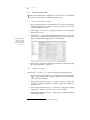
installation from eclipse update site
ϕnx comes with an Eclipse update site, which automates installation
and updates. It assumes, that Eclipse Juno (Modeling Tools) is
S
already downloaded from
and installed.
http://www.eclipse.org
.
1. Start Eclipse Juno
2. Click Help → Install new Software... to open the Eclipse update
manager
3. Click Add to add a new Papyrus1 update site. Sϕnx installation
retrieves its base graphical modeling libraries from this update
site.
4. Type the following into the location of the update site: http://
download.eclipse.org/modeling/mdt/papyrus/updates/releases/
juno
5. Click Add to add a new Sϕnx update site
6. Type the following into the location of the update site: http://
www.cis.jku.at/sphinx/updates/releases to use the latest tool
release. If you want to use nightly builds, use http://www.cis.
jku.at/sphinx/updates/nightly instead.
7. Follow the screen instructions to complete the installation
1 http://www.eclipse.org/papyrus/
1
To check for Sϕnx
updates, click Help
→ Check for Updates
2
installation
1.2
T
configuration
his section details the configuration of Sϕnx once it is installed.
Sϕnx uses KeYmaera as hybrid verification tool.
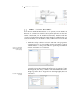
1.2.1 Install and Configure KeYmaera
1. Follow the instructions on the KeYmaera2 web site to download
and install KeYmaera locally. Note, that Sϕnx does not yet work
with the Webstart version!
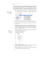
2. Click Eclipse → Preferences... and select KeYmaera Local Installation
from the tree view.
Specify the locations
of KeYmaera jar
libraries to enable
KeYmaera startup
from Sϕnx
3. Click Browse... on the KeYmaera Installation Directory line and
select your local KeYmaera installation directory. Sϕnx will try to
figure out the library dependencies automatically.
4. If necessary, supply the remaining jar libraries manually using
the respective Browse... buttons.
1.2.2 Configure the Editors
Click Eclipse → Preferences... to open the Eclipse preferences dialog.
1. Select DifferentialDynamicLogic → Compiler to activate/deactivate
LATEX code generation and configure output directory and further
code generation settings.
2. Select DifferentialDynamicLogic → Syntax Coloring to change the
coloring of terminal symbols, comments, and other syntactical
elements of dL.
3. Select DifferentialDynamicLogic → Templates to change the existing
templates or add new ones (see Sect. 1.2.4 for details).
4. Select DifferentialDynamicLogic → Refactoring to change the default
refactoring settings.
2 http://symbolaris.com/info/KeYmaera.html#download
1.2 configuration
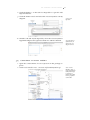
5. Select Papyrus → Embedded Editors to set the Sϕnx-included dL
editors as default popup editors for the uml elements Constraint,
OpaqueAction, and ControlFlow.
1.2.3 Show Additional Views
Click Window → Show View → Other..., then select the following views.
• Select General → Properties
• Select Papyrus → Model Explorer
1.2.4 Add Modeling Templates
3
Set the dL editors of
Sϕnx as embedded
popup editors for
Papyrus uml models
2
TEXTUAL MODELING
Abstract. This chapter introduces the textual modeling features of
Sϕnx. These include project creation wizard, loading dL models to
KeYmaera, model refactoring, syntax checking, code completion,
outline and quick outline, as well as code folding.
Contents
2.1
2.2
2.3
2.4
2.1
Create a new Project . . . .
Load a Model in KeYmaera
Refactor your Model . . . .
Further Editor Features . .
.
.
.
.
.
.
.
.
.
.
.
.
.
.
.
.
.
.
.
.
.
.
.
.
.
.
.
.
.
.
.
.
.
.
.
.
.
.
.
.
.
.
.
.
.
.
.
.
.
.
.
.
.
.
.
.
.
.
.
.
.
.
.
.
.
.
.
.
.
.
.
.
5
6
7
7
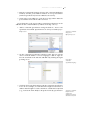
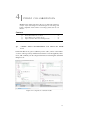
create a new project
1. Click File →New →Other...
2. Select Differential Dynamic Logic Project and click Next
Create a new dL
project using the new
project wizard
3. Enter the name of your new project and click Finish
The project creation wizard creates a new project with a sample .keyfile that shows the principal structure of a theorem in dL, including
a hybrid program. Details on dL can be found on the KeYmaera web
site1 , including tutorials and cheat sheets.
Below, we give a of a bouncing ball.
1 http://symbolaris.com/info/KeYmaera.html#download
5
6
textual modeling
2.2
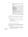
load a model in keymaera
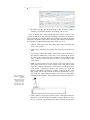
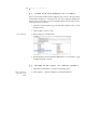
Sϕnx uses KeYmaera to prove models in dL. You can start KeYmaera
from the context menu of a .key or .key.proof file in the package explorer,
or from the context menu of a textual editor.
Figure 2.1: Run KeYmaera from the context menu of any .key or .proof file
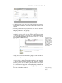
Sϕnx will start KeYmaera as external application and show KeYmaera’s
information output in a console view. If absolutely necessary, you can
stop KeYmaera from the console using the red stop button (not encouraged). Note, that this will force-quit KeYmaera without saving your
work.
Figure 2.2: The KeYmaera console.
2.3 refactor your model
2.3
7
refactor your model
Sϕnx has preliminary model refactoring support in the form of variable
renaming. Proofs are not yet adapted automatically.
1. Right-click a variable, select Refactor →Rename...
2.4
further editor features
• Double-click any tab to make it full-screen.
• Open a searchable quick-outline of your textual model from the
context menu of a dL textual model
Open the quick
outline using Ctrl-O
(Windows, Unix) or
Cmd-O (Mac)
• Syntax checking
Syntax and cross
references are checked
on-the-fly
• Code completion.
Get cross references
to variables and other
code completion help
by pressing
Ctrl-Space
• Keep overview with Code Folding using +/- in vertical editor bar.
Use code folding
• Quick peek folded content as tooltip + in vertical editor bar.
Hover the mouse over
a folded code snippet
to take a quick peek
8
textual modeling
• Whenever you save a dL textual model, Sϕnx generates a LATEX
representation of the model.
3
GRAPHICAL MODELING
Abstract. This chapter introduces the graphical modeling features
of Sϕnx. Sϕnx uses uml class diagrams to model the structure of a
hybrid system, and uml activity diagrams to model their behavior.
Graphical models can be transformed into textual dL models and
then loaded to KeYmaera.
Contents
3.1
3.2
3.3
3.4
3.1
Create a new Graphical Model
Model System Structure . . . .
Model System Dynamics . . .
Generate Textual Model . . . .
.
.
.
.
.
.
.
.
.
.
.
.
.
.
.
.
.
.
.
.
.
.
.
.
.
.
.
.
.
.
.
.
.
.
.
.
.
.
.
.
.
.
.
.
.
.
.
.
.
.
.
.
.
.
.
.
.
.
.
.
.
.
.
.
9
10
12
17
create a new graphical model
1. Click File → New → Other...
2. Select Papyrus Model and click Next
3. Enter the name of your new model and click Next
4. Select uml and click Next
5. Select uml Activity Diagram (system dynamics) and uml Class
Diagram (system structure), then check A UML model with basic
primitive types.
9
Create a new
graphical model of a
hybrid system
describing structure
and behavior
10
graphical modeling
6. Click Finish
The editor pane now shows the graphical editor. Switch to the class
diagram (structure) and follow the steps below to apply the uml profile
for dL.
1. In the Properties View, select the tab Profile and click the button
Apply Registered Profile.
2. Select Differential Dynamic Logic Structure and Differential Dynamic
Logic Behavior and click OK.
3. Check dldynamic and dlstatic and click OK.
3.2
model system structure
In this section, we discuss how to model the system structure with
classes and properties. We will use the stereotypes of the dL uml
profile to mark important parts of the model for code generation and
subsequent verification.
Create new classes by
dragging Class
elements from the
palette to the editing
area.
1. From the palette, select Class and click on the editing area. Alternatively, wait for the popup palette to appear in an empty
part of the editing area. We create two classes: one represents the
bouncing ball, the other one the world.
3.2 model system structure
11
2. On the properties view, select the profile element. Use System to
flag the main system class, and Object to flag other agents in the
system.
3. From the palette, select Property and click on a class to add a new
property. We add three properties to the class World: a clock t, a
damping coefficient c, and gravity g.
4. On the properties view, you can apply stereotypes Constant or
Variable to these properties to flag them as either being constant
or variable. By default, all properties are variable. Alternatively,
you can use the uml tab to set a property read only, or use the
popup editor to add {readOnly}
Flag properties as
constant or variable
using stereotypes,
setting readonly to
true/false on the uml
tab of the properties
view, or apply
{readOnly} with the
popup editor
5. Model associations between your classes, as appropriate. Currently, these are for documentation purposes only and do not
influence code generation.
6. Select Constraint from the palette to define conditions that must
always be true. In the bouncing ball example, we add constraints
on gravity (must be strictly positive), the damping coefficient
(must be positive and less than 1), time (must be positive), and
the initial height of the ball (must be positive). The popup editor
for constraints in dL supports syntax highlighting and code completion. You can confirm the constraint by pressing Ctrl-Enter, or
leave the popup editor with Esc.
Define constraints
using the dL popup
editor
12
graphical modeling
3.3
model system dynamics
Now that we defined the structure of our system, we can define its
discrete and continuous dynamics. Since system dynamics can become
rather complicated, we will model hierarchically. We start with the
overall system dynamics and will supply details in sub-diagrams. As
cautious modelers, we first define a safety condition before we model
any behavior.
Add a new constraint
as postcondition for a
uml activity
Select the constrained
element
1. Define the safety condition: select the tab uml of the properties
view and scroll to the precondition and postcondition section.
Click the button + on the postcondition to open the postcondition
window and add a new Constraint.
2. On the constraint definition window, name the constraint, and
optionally select the constrained element. In our example of the
bouncing ball, the safety condition will demand that the ball’s
height is positive but no larger than its starting height, thus we
constrain h.
3.3 model system dynamics
13
3. Exit the constrained element selection, the constraint definition
window, and the postcondition window. A new postcondition
(without specification) has been added to the activity.
4. Click on the postcondition to open the dL popup editor. Enter the
postcondition and confirm with Ctrl-Enter.
As an alternative to the popup editor, constraint specifications can be
added from the constraint editor (continue from step 2 above).
1. Add a constraint specification using the button + next to the
specification text field. Specifications are always of kind OpaqueExpression.
2. On the constraint specification window, name the new specification. Click the button + next to language to add dL. Type dL
into the text field on the left side and add it by clicking the rightpointing arrow.
3. Click into the body field and provide the constraint specification
in dL. In our example, we want the ball’s height to be between 0
and its initial height H. Click somewhere outside the body field
(e. g., reselect the name field) to adopt the new body specification.
Specify the constraint
using a new
OpaqueExpression
Enter dL as
constraint
specification language
Specify the constraint
body in dL and
confirm your
definition by clicking
outside the text field
14
graphical modeling
4. Exit the constraint specification window, the constraint window,
and the postcondition window by clicking OK on each.
Next, we define the overall system dynamics. These consist of the
continuous dynamics (the ball falls and jumps) and discrete dynamics
(when it hits the ground, the ball bounces back). We want the ball fall
and jump arbitrariliy often. Thus, discrete and continuous dynamics
are repeated non-deterministically many times in a loop.
1. Add an Initial Node from the palette. This node represents the
start of our system.
2. Add a Merge Node from the palette. This node represents the loop
start.
3. Connect the initial node and the merge node with a Control Flow.
The default condition for such a flow is true, which means that it
is executed unconditionally. The condition can be hidden using
Filter → Manage Connector Labels from the context menu of the
control flow.
Define the continuous
dynamics of a hybrid
system as
differential-algebraic
equation in the dL
popup editor of an
OpaqueAction with
stereotype Dynamics
4. Add an OpaqueAction from the palette and connect the merge
node with a control flow to the opaque action. This action represents the continuous dynamics of our system. On the properties
view, choose a descriptive name for the action (e. g., “Fall and
Jump”) and add the stereotype Dynamics on the properties view.
The opaque action represents the continuous dynamics in our system. Click the “Fall and Jump” label to open the dL popup editor
and define the dynamics using a differential-algebraic equation.
5. Add a Behavior Call Action from the palette. Although the discrete
dynamics of the bouncing ball example is rather simple, we want
to have a separate activity diagram to demonstrate decomposition.
3.3 model system dynamics
We create a new behavior named “DiscreteDynamics”.
15
Use Call Behavior
Actions to decompose
the dynamics and
create new Behavior
nodes
6. Add a Decision Node from the palette. This node represents the
end of the loop body.
7. Connect the decision node with the merge node using a Control
Flow as back edge. Select the stereotype Nondeterministic repetition for this control flow. Then specify a loop invariant for the
stereotype.
8. Add an Activity Final Node and connect the decision node with a
control flow. This finalizes the overall system dynamics as follows.
Overview of
bouncing ball
dynamics
16
graphical modeling
In the next step, we will specify the discrete dynamics of the system.
The discrete dynamics of the bouncing ball is rather simple: if the ball
hits the ground, it bounces back (i. e., the discrete dynamics inverts the
ball’s velocity and reduces it according to the damping factor), else it
just keeps falling or jumping (i. e., the discrete dynamics does nothing).
Use the context menu
to add a new activity
diagram to a uml
behavior
1. In the Model Editor view, add a New → Activity Diagram to the
DiscreteDynamics behavior created above using the context menu.
2. Add an Initial Node to denote the start of the discrete dynamics.
3. Connect the initial node to a decision node. This is the start of the
if-condition.
4. Add an Opaque Action to set the new velocity, and another one to
reset time. Tag both with the stereotype Deterministic Assignment
to define that they will set the value of variables in a deterministic
manner. Click the label of the action and set the values of velocity
(v := −c · v) and time (t := 0).
The discrete
dynamics of the
bouncing ball
example
5. Add a Merge Node, an Activity Final Node, and set the control flows
to get the final dynamics as below.
6. To set up navigation from the dynamics overview to the detailed
discrete dynamics, switch back to the tab Dynamics.
7. Double-click the behavior call action bounceback:DiscreteDynamics
to open the hyperlink configuration window.
3.4 generate textual model
17
8. Click the button + on the tab View Hyperlinks to open the Edit
Hyperlink Window.
9. Click the button Search and select the DiscreteDynamics activity
diagram.
10. Switch to the tab Default Hyperlinks, select the DiscreteDynamics
hyperlink and press the right-arrow button to add it as default.
3.4
Create a new
hyperlink
Set a hyperlink as
default action for
double-click on a
diagram element
generate textual model
1. Open the context menu of bouncingball.uml in the package explorer.
2. Click Acceleo Model to Text → Generate DifferentialDynamicLogic
Click Acceleo
Model to Text →
Generate DifferentialDynamicLogic
to generate a
textual dL model
from a graphical
uml model
4
P R O O F C O L L A B O R AT I O N
Abstract. This chapter introduces the proof collaboration features
of Sϕnx. Sϕnx uses Eclipse for model and proof versioning, and
is thus compatible with common versioning systems such as svn
and git.
Contents
4.1
4.2
4.3
4.4
4.1
Share and Collaborate on Textual Models . . .
Share and Collaborate on a Proof . . . . . . .
Export Open Goals of Partial Proofs . . . . . .
Import Geometric Relevance Filtering Results
.
.
.
.
.
.
.
.
.
.
.
.
.
.
.
.
.
.
.
.
.
.
.
.
.
.
.
.
19
20
20
22
share and collaborate on textual models
Textual models in dL, just as ordinary source code, can be versioned in
a source code repository. Differences between versions (updates, deletions, and conflicts) can be compared and resolved using the standard
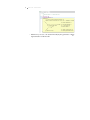
Eclipse tools.
Figure 4.1: Comparison of textual models
19
20
proof collaboration
4.2
share and collaborate on a proof
Just as for textual models, Sϕnx supports any source code repository
connected to Eclipse to version proofs. You can compare changes between your local version of a proof and the latest version in the source
code repository as follows.
1. Open the context menu of a proof and click Compare with → Latest
from Repository
2. Click Complete resource set(s)
Proof comparison
3. Browse the proof comparison
4. Use the buttons in the structural differences view header to copy
changes between versions
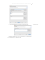
4.3
export open goals of partial proofs
1. Open the context menu of a proof and click Export...
Export an arithmetic
goal via the export
wizard
2. Select Sphinx → Export Arithmetic Goal and click Next
4.3 export open goals of partial proofs
21
3. Search for and select the open goal to export, click Next
Search an open goal
4. Select or create a new file to export, click Finish.
Select or create a new
file to export
22
proof collaboration
4.4
import geometric relevance filtering
results
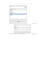
1. Open the context menu of a proof and click Import...
2. Select Sphinx → Geometric Relevance Filtering Result
3. Select a file from the file system or from the Eclipse workspace
Select hiding
suggestions
4. Select the hiding suggestions to import into the proof (usually all)
and click Next.
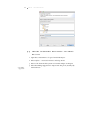
4.4 import geometric relevance filtering results
5. Select the applicable goals (usually all) and click Finish.
Commit the changes to the source code repository or load the partial
proof in KeYmaera to continue proving.
23
Select applicable goals