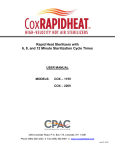
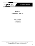
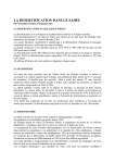
1
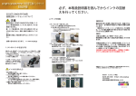
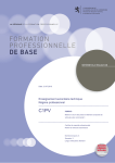
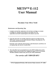
`
METS™
MODEL P-115
(115 VAC, 50/60 Hz)
USER’S MANUAL
•
•
•
INSTALLATION
OPERATION
MAINTENANCE
CPAC Equipment Division 2364 Leicester Road, Leicester, NY 14481
Phone (585)382-3223 Fax (585)382-3031 www.cpacequipment.com
3/02
IMPORTANT
ONLY silver bearing solutions should be run through your silver
recovery unit. This would include any tanks marked "Silver" or "B"
waste.
Tanks marked "sink", "A" waste or "Developer" should NEVER be
poured into the silver recovery unit. This may clog your cartridges,
resulting in ineffective performance.
ECOJET Tablets and waste from unused ECOJET tablets should
NEVER be put into the silver recovery unit.
If you are asked to put ECOJET tablets or waste into your silver
recovery unit, please call CPAC at 800-828-6011.
2
TABLE OF CONTENTS
Recommendations
4
Important Safeguards
4
Introduction
5
Installation
5–7
Operation
8
How to Change a METS-P-115 Cartridge
9
METS P-115 Specifications
10
Poppet Valve Removal
11
Bellows Pump Flow Adjusting Instructions
12
Optimal Performance Notice
13
Disclaimer
13
Statement of Warranty
14
3
RECOMMENDATIONS
Read the entire instruction manual before installation or operation of the METS
mini environmental treatment system. It will help you to understand the operation
of the system, how various sub assemblies work together and the operating
sequence of the controls.
WARNING: NEVER ATTEMPT TO PERFORM ANY ELECTRICAL
TROUBLESHOOTING ADJUSTMENT(S) OR SERVICE(S) UNLESS YOU ARE
A QUALIFIED ELECTRICIAN, ELECTRONICS TECHNICIAN OR FACTORY
TRAINED SERVICE TECHNICIAN.
IMPORTANT SAFEGUARDS
When using your METS mini environmental treatment system, these basic safety
precautions should be followed:
1. Read and understand all instructions.
2. Care must be taken to avoid burns from touching hot parts.
3. Do not operate this appliance with a damaged cord or if appliance has been
dropped or damaged until it has been examined by a qualified service
technician.
4. Do not let power cord hang over edge of table or counter or touch hot
surfaces.
5. An extension cord should not be used with this unit. The unit should be
plugged directly into a power outlet.
6. To protect against electrical shock hazard, do not immerse this appliance in
water or other liquids.
7. To avoid electrical shock hazard, do not disassemble this appliance. Call a
qualified service technician when service or repair work is required. Incorrect
reassembly can cause electric shock hazard when the appliance is switched
ON.
SAVE THESE INSTRUCTIONS
4
INTRODUCTION
The METS P-115 is designed to pump silver bearing liquid through one or two
metallic replacement cartridges. The METS metering pump controls the flow rate
(factory set at 60 mls/minute) to ensure the maximum amount of silver is
recovered.
The METS unit is ideal for minilabs, allowing them to meet though environmental
regulations for silver of 1mg/L (1 ppm) or less when used with RePAC 250 or Big
MO steel wool cartridges. Capacity performance will depend on silver
concentration, flow rate, solutions composition and pH (which must be below
7.8). These simple to operate units are easy to install and monitor.
INSTALLATION
The METS P-115 can be rolled to the processor where the operator manually
transfers overflow solution, or the silver bearing solution may be manually
transferred to the METS P-115 unit. Direct plumb operation may also be used.
Installation
1. Place the METS unit near both the C-41 and RA-4 processor, with access to
a floor drain and electrical outlet.
2.
For direct plumb applications, use plastic (PVC) “Y” or “T” fittings to connect
the RA-4 bleach-fix and stabilizer to the C-41 fixer and stabilizer.
NOTE: DO NOT RUN DEVELOPER THROUGH THE METS UNIT!
3. Connect the combined C-41 and RA-4 overflow to the inlet of the METS unit.
4. Connect the pump outlet to cartridge #1 inlet.
5. If two cartridges are used, connect the cartridge #1 outlet to cartridge #2 inlet.
6. Connect the cartridge #2 outlet to the drain. Make a gentle loop in drain tube
line after quick disconnect. (Creates an air barrier to decrease build-up)
7. Connect the safety overflow from the METS P-115 unit to the drain. If a drain
is not available, place a bottle or small tank near the unit with the safety
overflow hose inside this bottle or tank. If this container fills with liquid,
immediately check the unit for clogging or malfunctioning.
8. Check all hose fittings to ensure proper connections were made.
9. FILL HOLDING TANK WITH WATER PRIOR TO USE.
10. The unit is ready for operation.
5
ONE CARTRIDGE INSTALLATION
Cartridge #1
Drain
TWO CARTRIDGE INSTALLATION
Cartridge #1
Cartridge #2
Drain
6
“OFF-LINE” Installation
1. For an “OFF-LINE” installation, the METS P-115 unit is not directly plumbed
to the processor. Choose a location with access to a floor drain and electrical
outlet. The operator will be responsible for transferring processor overflows
to the METS P-115, or transporting the METS unit to the processors.
NOTE: DO NOT RUN DEVELOPER THROUGH THE METS UNIT!
2. Connect the pump outlet to cartridge #1 inlet.
3. If two cartridges are used, connect the cartridge #1 outlet to cartridge #2 inlet.
4. Connect cartridge #2 outlet to the drain. Make a gentle loop in drain tube line
after quick disconnect (creating an air barrier to decrease build-up).
5. Connect safety overflow from the METS P-115 unit to the drain.
6. Check all hose fittings to ensure proper connections were made. If drain is
not available, place a bottle or small tank (not supplied) inside the tray with
the safety overflow hose inside this bottle or tank. If this container fills with
liquid, immediately check unit for clogging or malfunctioning.
7. FILL HOLDING TANK WITH WATER PRIOR TO USE.
8. The unit is ready for “OFF-LINE” operation.
9. Prior to transporting the METS P-115 to the processors, disconnect the power
cord, cartridge #1 (from step 2), and safety overflow line.
10. After filling the METS unit with silver bearing liquid, repeat steps 2-8.
7
OPERATION
RePAC 250 or Big MO cartridges are recommended for METS P-115 units.
They can be ordered from CPAC at 800-828-6011. When using these cartridges,
a flow rate of 60-100 ml/minute is used. The first cartridge should be changed
after treating 900 gallons (based upon a starting concentration of 1.8 gm/L). This
is equivalent to 600 hours of operation. If your silver discharge limit is 5mg/L
(ppm), the cartridges may sustain a longer operating period.
For safety reasons, the METS P-115 unit is equipped with a 6 PSI pressure relief
valve.
Pump flow rate is factory set at 60 ml/minute. If an adjustment is necessary,
refer to BELLOWS PUMP FLOW ADJUSTING instructions.
For optimal performance and efficiency, the paper bleach-fix (and washless
stabilizer) and film fixer (& washless stabilizer) should be drained into the METS
collection tank together. This allows a uniform solution to be treated. METS
units plumbed directly to the processor will automatically receive this mixture.
Weekly Maintenance Procedure
EXTREMELY IMPORTANT!
Run two to three gallons of warm (or hot) water through the unit once a week by
pouring water into the holding tank. This reduces build-up in the cartridges, lines
and quick disconnects.
Controls
•
Power switch– turns the electrical power to the unit ON or OFF.
•
Liquid level switch – turns the metering pump OFF when the liquid level is
low, and ON when there is liquid in the holding tank.
8
HOW TO CHANGE A METS P-115 CARTRIDGE
1. Fill the holding tank of the METS P-115 unit with 2 gallons of water.
2. Allow all the water to pump through the cartridges (2 gallons will take 2
hours).
3. Turn off the power by using the power switch on the top cover.
4. Remove the new cartridge from the shipping container.
DO NOT THROW AWAY THE BOX.
5. Using the quick disconnect fittings on the cartridges, remove cartridge #1
from the machine. Set aside for draining.
6. If two cartridges are used, move cartridge #2 to the #1 position and reconnect
the units quick disconnect fitting to the bottom of the cartridge.
7. Place the new cartridge in the #2 position and connect top fitting of #1 to
bottom fitting of #2 cartridge.
8. Connect top fitting of #2 cartridge to drain or waste tank.
9. Turn machine on. Pour two gallons of water into the holding tank.
9
SPECIFICATIONS
Dimensions: 10"W x 20"L x 12"H (front)
without handle 10"W x 20"L x 17"H (back)
Electrical:
Weight:
115 VAC, 300 VA, 50/60 Hz
22 lbs (10 Kg)
10
POPPET VALVE REMOVAL, CLEANING AND INSTALLATION
PROCEDURES
1. Pinch off tubes near the pump’s connectors.
2. Unscrew connector nuts, pull off tubing and nut connector assemblies.
3. Remove valves from valve body;
a) Suction side – Pull valve out by the stem, the O-ring will come out with
the valve.
b) Discharge side – Use a small flat screwdriver to remove the o-ring.
With o-ring removed, pull valve out of the valve body with needle
nosed pliers.
4. Wash poppet valve assemblies or discard and replace.
5. Reinstall in reverse order of removal. Suction and discharge valves are
interchangeable. Valves are always installed before o-ring.
11
BELLOWS PUMP FLOW ADJUSTING INSTRUCTIONS
1. Do not attempt to adjust flow while pump is running.
2. Clockwise rotation of the adjusting screw increases pump stroke until
achieving 100% stroke. Do not attempt forced rotation of the adjusting screw
after indicator reaches 100% and a “bottoming “ resistance is experienced.
3. Counter-clockwise rotation of adjusting screw decreases stroke.
4. Only eight clockwise revolutions adjust stroke from 0% to 100%. One-half
inch bellows pump requires only four revolutions.
5. It is not necessary to loosen set screw.
NOTE: Do not add lubricants to any pump mechanism.
12
FOR BEST PERFORMANCE AND EFFICIENCY, THE PAPER
BLEACH-FIX (AND WASHLESS STABILIZER) AND FILM FIXER
(AND WASHLESS STABILIZER) SHOULD BE DRAINED INTO
THE METS COLLECTION TANK TOGETHER. THIS ALLOWS A
UNIFORM SOLUTION TO BE TREATED. METS UNITS PLUMBED
DIRECTLY TO THE METS UNITS WILL AUTOMATICALLY
RECEIVE THIS MIXTURE.
EVERY EFFORT HAS BEEN MADE TO INSURE THE COMPLETE
ACCURACY OF THE CONTENTS OF THIS MANUAL. NO
LIABILITY ARISING FORM ITS USE, HOWEVER, CAN BE
ACCEPTED BY THE COMPANY, WHO RESERVES THE RIGHT,
WITHOUT PRIOR NOTICE, TO ALTER THE SPECIFICATIONS,
CONSTRUCTION, OR CONTENT OF ITS EQUIPMENT AT THE
COMPANY’S OWN DISCRETION.
13
Statement of Warranty
All equipment is manufactured to exacting standards and has been tested and
inspected for proper workmanship and performance before shipping.
Any parts which are defective will be repaired or replaced within a one year
period after date of shipment, provided the equipment has been used according
to the instruction manual and have not been abused or tampered with.
The company will not be responsible for any damage resulting from leakage of
water or chemicals caused by improper installation, operator carelessness or
defective/loose plumbing fittings associated with installation and operation of the
equipment. The company assumes no responsibility for damage in transit and
the customer should resent any claim for such damage to the carrier.
This warranty gives you specific legal rights. You may also have additional rights
that vary from state to state.
Any unit to be repaired under warranty must be shipped, freight prepaid, or
delivered to a facility authorized to render services provided hereunder.
Returned unit must be either in its original package or a similar package affording
an equal degree of protection. All units must have a Material Return
Authorization code (MRA) visible on the returned item. MRA’s can be obtained
by calling 585-382-3223.
14