1
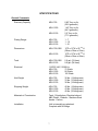
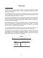
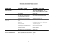
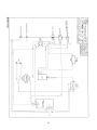
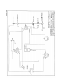
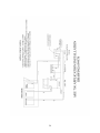
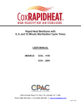
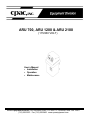
ARU 700, ARU 1200 & ARU 2100
(115/230 VOLT)
User’s Manual
• Installation
• Operation
• Maintenance
CPAC Equipment Division 2364 Leicester Road, P.O. Box 175, Leicester, New York 14481
(716) 382-3223 Fax (716) 382-9481 www.cpacequipment.com
TABLE OF CONTENTS
RECOMMENDATIONS
4
IMPORTANT SAFEGUARDS
4
DESCRIPTION
Items Included in Shipping Container
Automatic Terminal Electrolytic Silver Recovery
Efficient Recovery Automatically Matched to Your Needs
SPECIFICATIONS
5-6
5
6
6
7
CONTROLS
Figure 1-ARU Control Panel
LED Digital Display
Keypad
Status Lamps
8-9
8
8
8
9
INSTALLATION AND SET-UP
Connecting Unit to the Processor
Programming the ARU
Table 1
9 - 11
10
11
11
OPERATIONS
Table 2
Amp-Hours Key
Fail Safe Procedure
Set Point
Background Information
Effects
Changing the Point Setting
Cell Voltage Measurement
Volume Count (optional)
12-16
12
13
14
14
14
15
15
16
16
DESILVERING CATHODE
Desilvering Cathode by User
17
17
MAINTENANCE AND SERVICE
Preventative Maintenance
Regular Cleaning and Inspection
18-19
19
19
TROUBLE SHOOTING GUIDE
20 - 21
SCHEMATICS
22 - 26
2
SPARE PARTS LIST
27 - 29
DISCLAIMER
30
STATEMENT OF WARRANTY
31
3
RECOMMENDATIONS
Read the entire instruction manual before installation or operation of the ARU-700,
ARU-1200 and ARU-2100 silver recovery system. It will help you to understand the
operation of the system, how various sub assemblies work together, and the operating
sequence of the controls.
WARNING:
NEVER ATTEMPT TO PERFORM ANY ELECTRICAL
TROUBLESHOOTING ADJUSTMENT(S) OR SERVICE(S) UNLESS YOU
ARE A QUALIFIED ELECTRICIAN, ELECTRONICS TECHNICIAN, OR
FACTORY TRAINED SERVICE TECHNICIAN.
IMPORTANT SAFEGUARDS
When using your ARU-700, ARU-1200, and ARU-2100 silver recovery systems, these
basic safety precautions should be followed:
1. Read and understand all instructions.
2. Care must be taken to avoid burns from touching hot parts.
3. Do not operate this appliance with a damaged cord or if the appliance has been
dropped or damaged until it has been examined by a qualified service technician.
4. Do not let power cord hang over edge of table or counter or touch hot surfaces.
5. An extension cord should not be used with this unit. The unit should be plugged
directly into a power outlet.
6. To protect against electrical shock hazard, do not immerse this appliance in
water or other liquids.
7. To avoid electrical shock hazard, do not disassemble this appliance. Call a
qualified service technician when service or repair work is required.
Incorrect reassembly can cause electric shock hazard when the appliance is
switched on.
SAVE THESE INSTRUCTIONS
4
DESCRIPTION
General Comments
The ARU-700, ARU-1200, and ARU-2100 silver recovery units are designed to remove
silver electrolytically from photographic fixer solution. These compact efficient units are
manufactured from the finest materials and components, thus insuring many years of
reliable trouble-free operation.
Items Included in Shipping Container
1. Power head assembly, including:
a)
b)
c)
d)
e)
f)
plating power supply
motor drive
cathode drum
electrical cord
PCB with microprocessor and digital display
keypad controls
2. Complete tank assembly, including:
a)
b)
c)
d)
e)
factory installed fittings
drain tubing
tidy tray
four carbon anodes
anode/cathode support
3. Hook-up kit:
a)
b)
c)
d)
one PVC coupling 3/4” x 3/4”
one PVC reducer 3/4” x 1/2”
10’ of 3/4” tubing
hose clamps (2)
4. Information kit:
a) instruction manual and spare parts price list
b) silver test paper
c) warranty registration card
5
Automatic Terminal Electrolytic Silver Recovery
The ARU silver recovery units are automatic. They control and optimize plating current
as the silver concentration varies in the fixer solution. These units automatically
increase plating current during peak periods to recover all the silver possible, and
reduce plating current during slow periods to reduce sulfiding. The ARU units eliminate
the need for separate timers, fussy “wiring into the film processor”, or worry about
turning the unit OFF at night or weekends, and ON again in the morning. The
microprocessor regularly samples the silver concentration of the fixer solution and
automatically adjusts the plating current to match the working schedule and actual silver
recovery needs.
Efficient Recovery Automatically Matched to Your Needs
Since the ARU series automatically adjust their recovery rates to match silver
“production”, loss of precious silver to the drain is minimized. These units do not
require a timer, thus avoiding problems caused by timer schedules being disrupted by
power outages. These units also avoid loss of silver if emergency film is processed
during an “off” period. These units do not require separate probes or reference
solutions, thus avoiding frequent maintenance checks and solution calibration. Terminal
silver recovery units that use special probes often require frequent calibration with a
reference solution or cleaning of a sensing probe, and are often out of calibration,
resulting in loss of silver. The ARU series use a simple and unique method of regularly
measuring the silver concentration of the fixer solution. The sensing system is
completely self-contained in this unit and does not use sensitive probes or reference
solutions.
6
SPECIFICATIONS
General Comments
Recovery Capacity
ARU-700
0.83 Troy oz./hr.
(25.8 grams/hr.)
ARU-1200
1.43 Troy oz./hr.
(44.3 grams/hr.)
ARU-2100
2.5 Troy oz./hr.
(77.5 grams/hr.)
Plating Range
ARU-700
ARU-1200
ARU-2100
1-7
1 - 12
1 - 21
Dimensions
ARU-700/1200
15"D x 15"W x 20 3/8"H
(38cm x 38cm x 52cm)
ARU-2100
15"D x 15"W x 26 5/8"H
(38cm x 38cm x 68cm)
Tank
ARU-700/1200
ARU-2100
5.0 gal. (19 liters)
9.0 gal. (34 liters)
Electrical
115/230 VAC, 50/60 Hz
ARU-700
75 Watts
ARU-1200
90 Watts
ARU-2100
105 Watts
Net Weight
ARU-700
ARU-1200
ARU-2100
30 lbs. (14 kilograms)
33 lbs. (15 kilograms)
38 lbs. (18 kilograms)
Shipping Weight
ARU-700
ARU-1200
ARU-2100
40 lbs. (18 kilograms)
43 lbs. (19 kilograms)
49 lbs. (22 kilograms)
Materials of Construction
Tank - Polyethylene, Electrical shroud
ABS Plastic, Cathode - Stainless Steel
Anode - Carbon
Installation
Unit is internally pre-plumbed.
Complete with all fittings.
7
CONTROLS
Front Panel of Silver Recovery Unit
LED Digital Display
Amperes
This display shows the present plating current.
Keypad
Control
Function______
Volume Count (optional)
Will display the number of liters of fixer replenishment
used (feature only works if current ring is installed).
________________________________________________
Set Point
Will display the set point calibration number.
____________________________________________________
Amp-Hours
Will display the current amp-hours timer, and then the
units lifetime amp-hours timer.
_______________________________________________________________
Set
Pushing this key activates an indicator light
behind the key. When the light is on- the operator
can make permanent changes to the set point and
amperage settings.
_____
__________________
Amperes
Pushing once will display the high current amps and
pushing again will display low current amps.
_____________________________________________________________________
Increase/Decrease
These keys are used to set the values of various system
functions.
8
Status Lamps
Control
Function
Operation__________
Standby
The unit is idle. It will start
desilvering when the 15 minute
stand-by timer expires.
Lamp is lit in STANDBY mode only.
High Current
The unit is desilvering at the
high current setting.
Low Current
The unit is desilvering at
the low current setting.
Lamp is lit in high
current cycle, and
in sampling cycle
after a high current
cycle.
_____________________________________________________________________
Lamp is lit in low
current cycle, and
in sampling cycle after
a low current cycle.
_____________________________________________________________________
INSTALLATION AND SET-UP
General Comments
1. Remove the ARU from shipping container and check for signs of damage such
as cracked tanks, broken fittings, etc.
Notify CPAC immediately if any
damage exists. Remove all packing materials including the packing between the
cathode and anodes and save.
2. Position the system three to four feet from a grounded 120 VAC, 2 Amp power
source. ( 230 VAC 1 Amp power source for export units). Check the rating plate
label for the voltage.
3. Drain provisions must be provided for the unit as well as other accessories used.
4. Connect the safety overflow hose to a drain.
5. Connect the silver bearing overflow hose from the processor(s) to either a solution
collecting tank or directly to the ARU tank inlet.
CAUTION: Use hose clamps on all connections to prevent leaks.
9
Connecting Unit to the Processor
1. Place the silver recovery unit in a convenient location within easy access to a drain
and a 115/230 VAC grounded electrical supply.
2. Inspect all bulkhead fittings (inlet, outlet, drain) on ARU tank to insure
tightness.
3. Securely attach ARU inlet tubing to the processor’s fixer overflow connection.
CAUTION: Severe bends and kinks in tubing will result in blockage of flow. For your
convenience, a tubing hook-up kit consisting of one PVC 3/4” x 3/4” coupling and one
PVC 3/4” x 1/2” reducer has been provided.
4. Place ARU outlet tubing in the nearest chemical resistant drain to the sewer.
(In any event, conform to prevailing local ordinances.) If the sewer drain is higher
than the ARU outlet, place the unit on a stand, which elevates the outlet above
the sewer drain.
5. Fill the ARU tank with silver-laden fixer to the level of the outlet fitting.
6. ARU units are available as 115 or 230VAC. Be sure the power supply matches the
voltage requirement of the unit (the voltage requirement is printed on the back of the
powerhead). Plug the ARU power cord into 115/230 VAC electrical outlet, which is
properly grounded. Some processors have 115/230 VAC accessory electrical
outlets, which may be used.
7. Turn the unit ON.
10
Programming the ARU
1. The various ARU units are factory programmed as indicated in Table 1 below. All of
these parameters can be changed and other values reprogrammed into the unit.
TABLE 1
Factory Settings
Model
ARU-700
ARU-1200
ARU-2100
Set Point
30
30
30
High Current (A)
5
8
13
Low Current (A)
2
3
6
Fixer
Replenishment
Rate (mL/min.)
250
250
250
2. To reprogram the unit, use the following keys. Their functions are described below:
SET: Press this key to enter the programming mode. The display will go blank. A
light in the upper right corner of the key glows indicating that the microprocessor is
in the “SET” mode and values can now be changed.
SET POINT: Pressing this key will cause the set point to be displayed and flashed,
which indicates that it can be changed. Change this setting by using the INCREASE
or DECREASE key. See the section on OPERATION for a detailed explanation of
this setting.
AMPERES: Pressing this key once will cause the high current setting to be
displayed and flashed (i.e. H 10), which indicates that it can be changed. Change
this setting by using the INCREASE or DECREASE key. Pressing this key again will
cause the low current setting to be displayed and flashed (i.e. L 5). Change this
setting by again using the INCREASE or DECREASE key. In order to toggle back
and forth between the two current settings, continue to press this key. The
microprocessor will prevent the operator from programming the high and low current
settings too close to each other in order to ensure proper operation. The two
settings cannot be less than 3 amps apart for the ARU-700, 5 amps apart for the
ARU-1200, and 7 amps apart for the ARU-2100.
3. When using the INCREASE or DECREASE key, each time the arrow is pressed, the
value will change by one. Holding down an arrow will change the value rapidly after
an initial delay of about one second. Use this rapid change to get near the aim
value and then use individual pushes until the exact value is reached.
4. When all programming is complete, press the SET key. The light in the upper right
corner of the key will go out, and the new values entered into the microprocessor.
Note that it is not mandatory to make all the above changes before pressing this
key. New parameters can be entered into the system at any time by pressing the
SET key.
11
OPERATIONS
General Comments
The ARU silver recovery unit follows a pattern of desilvering, sampling and standby
cycles in order to constantly monitor the silver concentration and adjust the current
(amperage) accordingly.
The desilvering cycle lasts for three (3) minutes during which time the unit will be plating
silver in either high or low current mode. At the end of each desilvering cycle, the unit
enters a sampling cycle that lasts for 15 seconds.
At the end of the sampling cycle, the microprocessor measures the cell voltage to
determine whether the unit will start another desilvering cycle or enter a standby cycle.
If the ARU unit enters a standby cycle, desilvering is halted for fifteen (15) minutes, at
the end of which it starts up again.
The first desilvering cycle after the unit is initially turned on and also after a standby
cycle, is in low current for 1.5 minutes instead of the normal 3 minutes. This feature
limits the amount of desilvering time if no silver-laden fix is added for an extended
period of time (i.e. overnight or over the weekend).
The microprocessor will force a desilvering cycle into low current mode, whenever the
temporary AMP-HOURS timer is below the value as indicated in Table 2 below.
This feature allows a bare cathode to buildup a solid base of silver and also eliminates
the changes a bare cathode has on the setpoint calibration. See the section on the
AMP-HOURS key for more details on utilizing this feature by resetting the temporary
amp-hours timer every time the cathode is desilvered.
TABLE 2
Minimum Value of Temporary Amp-Hours Timer
Model
Amp-Hours (A-hrs.)
ARU-700
ARU-1200
ARU-2100
4
6
12
12
AMP-HOURS Key
The AMP-HOURS key enables the operator to monitor the recovery rate of the unit.
There are two amp-hours timer values that the microprocessor keeps stored in its
memory.
The first is the temporary amp-hours timer, which is resettable, and should be reset to
zero every time the cathode is desilvered. This will enable the operator to monitor how
much silver has plated on the cathode assuming an average recovery efficiency, and
will also enable the low current initial plating feature. In order to reset the temporary
amp-hours timer, press and hold down both the AMP-HOURS and DECREASE keys
until the 5 second reset timer on the display counts down to zero.
The value of the temporary amp-hours timer can also be used to calculate the recovery
efficiency of the unit. This can be done by performing the following steps:
1. Calculate the troy-ounces (or grams) of silver plated at 100% efficiency by taking the
number of temporary amp-hours since the cathode was last desilvered and multiply
by 0.128 (multiply by 4 to calculate grams of silver plated).
2. Weigh the troy-ounces (or grams) of silver recovered from the cathode after
desilvering.
3. Divide the value in Step 2 by the value in Step 1, and then multiply by 100 to
calculate the recovery efficiency percentage (%).
4. If the recovery efficiency calculated in Step 3 is less than 80% the unit is operating
too long in desilvering mode with no silver left in solution, and indicates the set point
is too high. Lower the set point as described in the section "Programming the ARU".
The second value the unit keeps track of is the permanent amp-hours timer, which is
non-resettable and therefore equals the number of amp-hours during the lifetime of the
unit.
Press and hold down the AMP-HOURS key to view the value of the two timers. The
temporary amp-hours timer is displayed for the first 4 seconds and the permanent amphours timer is displayed thereafter. If either timer exceeds 10,000 the value will be
displayed exponentially. The integer base will be displayed for 2 seconds and then the
base 10 exponent (i.e. 26,500 -> base display = 2650 and exponent display = E1). The
base exponent is the number of zeros added to the end of the integer base to obtain
the timer value.
13
Fail Safe Procedures
Internally the microprocessor continually checks for mechanical and/or electrical
problems. Any problem affecting the plating action will be detected. The digital display
will show "ERR 1" if the unit cannot reach the programmed amperage. The display will
then show in sequence, "ERR 1/LO-A". This could be caused by the desilvering tank
not filled, too low silver content of the chemicals, electrical connections not clean, etc.
The message will continue to show until the problem is corrected. When a problem,
such as a broken wire is corrected, the desilvering cycle will begin where it left off.
SET POINT
The set point is displayed as a range of 0 to 60 (factory default = 30). Each increment
is equal to 10 mV, 0 = 300 mV, 30 = 600 mV, and 60 = 900 mV. The ARU system
actually works with two set points, the set point that can be adjusted and displayed is
the HIGH set point, the LOW set point is automatically calculated to be 50 mV less than
the HIGH set point.
Background Information
There is a relationship between plating current and silver concentration in the
electrolyte (silver bearing fixer solution) of the silver recovery unit. When a large
quantity of silver is present in the fixer, there is less resistance between the anode and
cathode, which results in a lower plating voltage. As the silver is removed from fixer,
more resistance occurs between the anode and a higher plating voltage will be required
to maintain the plating current setting.
The ARU control PCB uses the anode and cathode as a sensor. Every three minutes
(desilvering cycle), the unit stops plating for fifteen seconds (sampling cycle) and
measures its own cell voltage. If the measured cell voltage is below the LOW set point,
the silver recovery unit will plate on the HIGH current setting. When the cell voltage is
equal to or above the LOW set point and below the HIGH set point, the unit will plate on
the LOW current setting. If the cell voltage is equal to or above the HIGH set point, the
unit will cease plating and enter the standby cycle.
For example:
HIGH
Set Point
LOW
Set Point
Cell Voltage Measured
in Silver Recovery Unit
Plating
Current
I 600 mV (30)
II 600 mV (30)
III 600 mV (30)
550 mV (25)
550 mV (25)
550 mV (25)
500 mV (20)
550 mV (25)
600 mV (30)
High
Low
Standby
14
Effects
Higher set point settings will keep the unit operating on high plating current more, and
take silver concentration to a lower level. Too high a setting will cause sulfiding.
Lower set point settings will give harder plate and keep the unit operating on low plating
current more. Too low a setting will result in silver being lost to drain.
Generally, the correct set point setting will plate silver on the cathode that is typically
dark brown to light gray in color and granular in texture.
Changing the Set Point Setting
The set point is a calibration number that determines how much silver is removed from
the chemistry. If the unit is not removing enough silver, the set point should be raised.
If it is removing too much silver, the set point should be lowered. It is not practical to
change the calibration during installation because the calibration will change after the
cathode has an initial coating of silver. Also, the unit will plate the initial coating of silver
in low current mode only, so changing the set point during installation will have no effect
until the minimum temporary amp-hours value listed in Table 2 is reached. It is
recommended that the set point be left at the factory setting unless the plating is not
satisfactory after the cathode has a coating of silver.
To make a change to the set point:
1. Let the unit plate for several cycles as it is.
2. Press the SET POINT and AMP-HOURS keys. The value shown on the digital
display reflects the silver level from the last sample period. Record this value.
3. Press the SET POINT key. The current set point will be displayed on the digital.
Record this value.
4. The value from Step 3 is compared to the value from Step 2 to determine the plating
mode that will be selected.
•
If the value from Step 2 is greater than, or equal to, the value from Step 3 - the
unit will go into STANDBY.
•
If the value from Step 2 is 6 or more below the value from Step 3 - the unit will
plate in HIGH current.
•
If the value from Step 2 is less than the value from Step 3, but is not 6 or more
below the value from Step 3 - the unit will plate in LOW current.
Change the set point setting in order to adjust the calibration point at which the recovery
unit will switch plating cycles (High, Low and Standby). The recommended increase or
decrease in the set point at any one time is 1 or 2 (10 or 20 mV), and should be based
on analysis of several samples recorded in Step 2 above.
15
Cell Voltage Measurement
The cell voltage is constantly being measured by the PCB and can be viewed in
millivolts on the display as long as both the INCREASE and DECREASE keys are
pressed at the same time. This feature is useful in determining whether the plating
power supply is providing a DC voltage source to the recovery cell.
For extensive trouble shooting, the cell voltage can be displayed without having to hold
down the INCREASE and DECREASE keys by first pressing the SET key to enter the
programming mode. Next, briefly press the INCREASE and DECREASE keys at the
same time to display the cell voltage. Press the SET key again to exit the programming
mode and the display will return to showing the amperage.
Volume Count (optional)
The volume count feature allows the user to program the fixer replenishment pump rate
(in ml/min.) into the microprocessors memory, and then utilize a current ring (current
sensing device) to monitor the run time of the replenishment pump. These two valves
will be used to calculate the fixer replenishment volume or volume count.
The volume count measured in liters is a re-settable counter, which can be viewed on
the display by pressing the VOLUME COUNT key. In order to reset the volume count
back to zero, press and hold both the VOLUME COUNT and DECREASE keys until the
5 second reset timer on the display counts down to zero.
Program the fixer replenishment pump rate in ml/min. by first pressing the SET key to
enter the programming mode. Next, press the VOLUME COUNT key and the current
pump rate setting will be displayed and flashed. Use the INCREASE or DECREASE
keys to change the setting. Finally, press the SET key again to exit programming mode
and store new setting in microprocessor's memory.
The optional current ring is clamped on one of the electrical wires to the fix
replenishment pump. It can be connected around either the hot or the neutral wire, but
only one wire goes through the ring of the current sensor. Follow the unit schematic to
connect the current ring signal wires if the current ring was not factory installed. The
current ring will send a low voltage signal to the PCB whenever the pump is on.
The replenisher pump must draw .5 amps for the current sensor to work correctly. If
the pump does not draw this much current, simply loop the electrical wire from the
replenishment pump through the ring several times.
16
DESILVERING CATHODE
General Comments
Ideally, wait until you have recovered approximately 6 to 10 pounds of silver on the
SRU cathode (1/2 to 3/4 inch build-up) before stripping the silver. To remove the silver,
follow these steps:
Desilvering Cathode by User
1. Equipment required:
a) 1/2 inch wrench
b) putty knife, approximately one inch wide
c) large plastic bag (Optional)
2. Unplug unit.
3. Lift the top half of the unit (power head and cathode) straight up from the tank. The
silver-laden cathode is attached to the bottom of the powerhead. Set the top down
on a flat surface, preferably on a piece of plastic, or in a shallow pan, to catch fixer
drips.
5. To remove cathode, loosen the hex head bolt on the coupling with standard 1/2"
wrench. Power head will easily separate from silver-laden cathode.
5. With a putty knife or similar tool, scrape the silver from cathode. Experience has
shown that it may be cleaner and more convenient if you put the cathode in large
plastic bag during scraping.
6. Reinstall the cathode by inserting it into the cathode coupling; securely tighten the
coupling bolt, and replace power head on tank.
7. To insure proper and continuing operation, check all hoses for possible leaks, kinks
and to be sure that outlet hose is in the appropriate drain to sewer.
17
MAINTENANCE AND SERVICE
(TO BE DONE ONLY BY A QUALIFIED TECHNICIAN)
General Comments
1. Unplug unit from wall power.
2. Remove housing cover by taking out two screws on each side of the cover.
Remove four screws in the corners of the large aluminum plate. Remove cathode
contact brush lead from shunt. Lift entire electrical assembly straight up (by
pulling up on the motor).
3. You are now looking at the tank cover complete with the motor coupling, contact
brush spring, and bracket. This is a primary area of lost amperage. Check the set
screw holding the bronze motor coupler onto the cathode drive shaft. Remove
the motor coupler and the stainless steel cathode drive shaft. Clean these parts
thoroughly inside and out. Inspect the plastic rulon bearing and the teflon seal.
Replace if worn.
4. Reassemble, using a generous amount of grease between the rulon bearing and the
teflon seal. Make sure the stainless steel washer is installed between the bronze
motor coupling and the flanged rulon bearing. If this washer is not installed, the
flanged bearing will wear excessively. When reassembling, be sure the set screw is
tight – it must dig into the shaft. Allow approximately .020 end play between the
cathode drive shaft and bearing (.020 thickness is approximately the thickness of a
business card). Refer to Drawing 699601 for a detailed drawing of assembly.
5. Clean the contact brush. A small burr or particle can cut amperage substantially.
6. Replace the electrical assembly. Reconnect cathode contact brush lead to
current shunt and tighten nut securely. Replace the four screws in the corners of
aluminum plate.
7. Check all DC electrical connections. These connections must be perfect, clean
and very tight.
8. Check hoses and bulkhead fittings to see that there are no leaks or restrictions.
9. Check lock washers, anode bolts and nuts.
Replace corroded bolts.
Remove any corroded washers.
10. Tighten all anode bolts.
11. Check, clean, and tighten ground wire terminal connection at ground strap.
12. Replace the power head and housing cover.
13. Plug unit into the power outlet. Turn unit ON
18
Preventive Maintenance
The moving parts of the ARU units are designed and built so they do not need frequent
lubrication. The flanged sleeve bearing in the tank cover hub and the gear motor never
need to be lubricated after they leave the factory.
Regular Cleaning and Inspection
This is very IMPORTANT. Keep the unit clean by using a rag dampened with “Spic-NSpan” (or similar household cleaner). Pay particular attention to cleaning the area of
the anode brackets since these brackets will corrode if fixer comes in contact with them.
(Corrosion can result in lower plating efficiency.)
Visually check the status LED's and digital display to insure that the unit is working
properly and the power is ON.
Yearly, or when unit is moved from place to place, check plumbing for signs of leaking,
restrictive kinks, etc.
A qualified technician should check all electrical screw-attached points for good
conductivity, such as the ground wire. An especially important point to check is the set
screws in the bronze motor coupling and cathode drive shaft to make sure they are
tight.
19
TROUBLE SHOOTING GUIDE
SYMPTOMS
POSSIBLE CAUSE
PROBABLE SOLUTION
Fixer leak or crystallizing around inlet,
outlet or drain fitting.
Loose bulkhead fitting or tubing.
Tighten fittings or tubing joints. For very bad
leaks, remove and clean fittings. After
cleaning, securely reinstall fittings to hold tank.
Cracked fitting.
The drain opening to sewer is higher
than ARU outlet, preventing solution
from gravity feeding to sewer drain.
Replace fitting.
Put silver recovery unit on a stand so its' drain
outlet is higher than sewer drain opening.
Outlet tubing has a kink or blockage.
Unit incorrectly installed and not getting
power.
Straighten tubing and/or kink.
Check electrical source
Blown fuse.
Investigate and remedy cause. Replace fuse.
Unit not turned ON.
Turn power supply ON.
Cathode grossly overloaded with silver.
Remove silver from cathode.
Capacitor burned out.
Replace capacitor.
Low or no cell current.
Motor burned out or gears malfunctioning.
Fixer corroded anode bracket.
Replace motor.
Replace anode ground bracket.
ERR 1/LO-A flashing on display.
Anode ground wire loose or not connected.
Connect.
Anode carbon mount screws loose.
Tighten.
Fixer overflowing top of tank.
Motor not running and or all status
LED's not lit.
20
SYMPTOMS
POSSIBLE CAUSE
PROBABLE SOLUTION
Low or no cell current.
Cathode not securely fastened to power
head.
Securely tighten cathode coupling screw to
power head.
ERR 1/LO-A flashing on display.
Set screw holding motor coupler to cathode
coupling has loosened.
Tighten set screw in motor coupler.
Cathode contact brush worn out.
Unit has been ON for too long a period of
time. All of the silver has been removed
from fixer.
Recovery unit ON too long.
Replace cathode contact brush.
Lower set point and or current settings.
Recovery from bleach-fix.
Unit won't recover silver from bleach fix.
Cathode contaminated with grease and or
oil.
Sulphiding (rotten egg smell coming
from silver recovery unit)
Silver falling off cathode.
Check electrical source
No silver collecting on cathode.
Solution is not fixer.
Clean cathode with clean cloth and scouring
powder (comet, etc.) and water; rinse thoroughly
in water to remove contaminates.
Use silver laden fixer.
ON/OFF switch ON, no power.
No silver in fixer.
Blown fuse.
Use silver laden fixer.
Investigate and remedy cause, replace fuse.
21
22
23
24
25
26
ARU-700
(115/230 VAC, 50/60 Hz)
SPARE PARTS LIST
CPAC
PART NO.
602997
28-107P2012
602880
701094
703134
70-107A8028B
SP-124B8002
603049
05-139A9001D
703191
SP-107M0099
SP-107M0033
603027
DESCRIPTION
Motor Assy
Diode, Rectifier
PCB
Fuse, 1A, Slo-Blo
Transformer, plating
Anode
Cathode
Brush Assy
Bearing, rulon
Seal, teflon
Motor Coupling Kit (consisting of):
(1) 09-107A9024B - Coupling, motor
(1) 48-111P2012 - Set screw
(1) 50-107P2040 - Washer, flat
Cathode Coupling Kit (consisting of):
(1) 09-107A9044F - Shaft, drive
(1) 51-107P2022 - Bolt, hex head
Seal-Bearing Kit (consisting of):
(1) 05-139A9001D - Bearing
(1) 703191 - Seal
(1) SP-107M0099 - Motor Coupling Kit
(1) SP-107M0033 - Cathode Coupling Kit
(1) 50-114A9092A - Load Washer
27
ARU-1200
(115/230 VAC, 50/60 Hz)
SPARE PARTS LIST
CPAC
PART NO.
602997
28-107P2012
603007
700629
703135
70-107A8028B
SP-107A8019
603049
05-139A9001D
703191
SP-107M0099
SP-107M0033
603027
DESCRIPTION
Motor Assy
Diode, Rectifier
PCB
Fuse, 2A, Slo-Blo
Transformer, plating
Anode
Cathode
Brush Assy
Bearing, rulon
Seal, teflon
Motor Coupling Kit (consisting of):
(1) 09-107A9024B - Coupling, motor
(1) 48-111P2012 - Set screw
(1) 50-107P2040 - Washer, flat
Cathode Coupling Kit (consisting of):
(1) 09-107A9044F - Shaft, drive
(1) 51-107P2022 - Bolt, hex head
Seal-Bearing Kit (consisting of):
(1) 05-139A9001D - Bearing
(1) 703191 - Seal
(1) SP-107M0099 - Motor Coupling Kit
(1) SP-107M0033 - Cathode Coupling Kit
(1) 50-114A9092A - Load Washer
28
ARU-2100
(115/230 VAC, 50/60 Hz)
SPARE PARTS LIST
CPAC
PART NO.
602997
28-107P2012
603008
700629
703135
70-107A8029B
SP-107A8020
603049
05-139A9001D
703191
SP-107M0099
SP-107M0033
603027
DESCRIPTION
Motor Assy
Diode, Rectifier
PCB
Fuse, 2A, Slo-Blo
Transformer, plating
Anode
Cathode
Brush Assy
Bearing, rulon
Seal, teflon
Motor Coupling Kit (consisting of):
(1) 09-107A9024B - Coupling, motor
(1) 48-111P2012 - Set screw
(1) 50-107P2040 - Washer, flat
Cathode Coupling Kit (consisting of):
(1) 09-107A9044F - Shaft, drive
(1) 51-107P2022 - Bolt, hex head
Seal-Bearing Kit (consisting of):
(1) 05-139A9001D - Bearing
(1) 703191 - Seal
(1) SP-107M0099 - Motor Coupling Kit
(1) SP-107M0033 - Cathode Coupling Kit
(1) 50-114A9092A - Load Washer
29
EVERY EFFORT HAS BEEN MADE TO INSURE THE COMPLETE
ACCURACY OF THE CONTENTS OF THIS MANUAL. NO LIABILITY
ARISING FROM ITS USE, HOWEVER, CAN BE ACCEPTED BY THE
COMPANY, WHO RESERVES THE RIGHT, WITHOUT PRIOR NOTICE,
TO ALTER THE SPECIFICATIONS, CONSTRUCTION, OR CONTENT OF
ITS EQUIPMENT AT THE COMPANY’S OWN DISCRETION.
30
Statement of Warranty
All equipment is manufactured to exacting standards and has been tested and
inspected for proper workmanship and performance before shipping.
Any parts which are defective will be repaired or replaced within a one year period after
date of shipment, provided the equipment has been used according to the instruction
manual and have not been abused or tampered with.
The company will not be responsible for any damage resulting from leakage of water or
chemicals caused by improper installation, operator carelessness or defective/loose
plumbing fittings associated with installation and operation of the equipment. The
company assumes no responsibility for damage in transit and the customer should
resent any claim for such damage to the carrier.
This warranty gives you specific legal rights. You may also have additional rights that
vary from state to state.
Any unit to be repaired under warranty must be shipped, freight prepaid, or delivered to
a facility authorized to render services provided hereunder. Returned unit must be
either in its original package or a similar package affording an equal degree of
protection. All units must have a Material Return Authorization code (MRA) visible on
the returned item. MRA’s can be obtained by calling
716-382-3223.
31