1
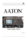
Digital Micro Force 2 Manual
ver. 1.2
Preston Cinema Systems • 1659 Eleventh Street • Santa Monica, CA 90404
fig.1. Digital Micro Force 2 control descriptions
LEMO receptacle
Camera
Run
Switch
Threaded well
for bracket
Set zoom
limits
Reset
zoom
limits
Zap Switch
Set soft
stop limits
Zoom
Sensitivity
display
Motor
Direction
Joystick
Calibrate
lens end
stops
Zoom Bargraph
position indicator
Zoom marking strip
Zoom
Sensitivity
adjustment
knob
fig. 2 Microforce control with Pan Arm Adapter accessory p/n 1155 for ¾” and 17mm pan bars.
Digital Microforce 2
1. Introduction. The new Digital Microforce 2 builds upon the same robust force sensor technology
which made the Micro Force an industry standard. The Digital Microforce 2 features automatic lens
calibration, electronic limit setting, and a bright LED bargraph display of zoom position. This latest
version adds programmable soft stops and a new speed control knob with a digital readout.
The rugged housing, machined from solid aluminum alloy, protects the control from mechanical
abuse and assures years of reliable operation. Its ergonomic design provides a rounded grip for
comfortable all day use and also offers a convenient attachment point for its mating Pan Arm
adapter. The new speed control knob is virtually indestructible. It turns with glassy smoothness that
reflects on the careful design used throughout.
The unit can drive the DM1, DM2 or DM1X digital motors. Its powerful drive capability assures
trouble free operation with even the largest zoom lenses. Motor connection is made via a series of
molded "Y" cables. These cables are available for both film and video cameras and allow the Digital
Microforce 2 to remotely control the camera run/stop or VTR functions respectively.
The Digital Microforce 2 also supplies the analog command signal for controlling the zoom channel
of the FI+Z system, the internal servos of video lenses, or the Radio Micro Force wireless module.
2. Power Connections. The Micro Force may be powered using the following types of cables:
a. "Y" -Cables: (product series 1200) for specific film and video cameras. Micro Force power is
drawn directly from the accessory socket on the camera.
b. Video Cables for Canon, Fujinon and Nikon lenses. Power is drawn from the 12 pin Hirose
connector on the lens.
c. Zoom cables (series 4444, 4445) for use with the FI+Z system.
d. Auxiliary power cables (product series 1128-1130) may be used in conjunction with "Y"
cables to power the control directly from a battery.
3. Power requirements. The Micro Force operates over a voltage range of 11 - 30 VDC (max). Idle
current is 55mA at 24 VDC or 95mA at 12VDC. The maximum current drawn under stalled motor
conditions is 1.2A @ 24V (typ.) or 2.4A at 12V. The actual current requirement is proportional to the
operating torque and the current limit set on the circuit board.
4. Operating Procedures. CAUTION. The motor will start rotation as soon as power is applied to the
unit. Make sure your hand is clear of the moving gear!
a. Attach the DM1, DM1X, or DM2 motor to the matte box support rods using a 19mm motor
swing arm (product series 4300) with a step down bushing for 15mm or .625" rods if
required. Make certain that the rods are secured against rotation. Use the Arri or Panavision
Bridge (4304, 4311) to prevent 15mm or .625" rods from twisting.
b. Position the motor so that its gear teeth are engaged with the corresponding teeth on the
zoom ring of the lens. Auxiliary gears (product series 4231, 4240, 4241) are available to
enable the motor to drive either Panavision 48 DP gearing or .50m / .60m gears for Canon
and Fujinon video lenses.
c. Check that the gears are meshed just tightly enough to eliminate any play but not so tightly
as to cause the gears to jam.
d. Connect the Microforce 2 to its power source. The green LED power indicator should be
illuminated.
e. The motor will calibrate by finding the mechanical end stops of the lens. During this phase
the motor current is limited to a low value so as not to apply excessive force to the lens. The
bar graph indication will remain dark until this operation is completed.
f. After finding the end stops of the lens, the motor stops and the bargraph indicator will light
indicating the position of the zoom setting.
g. The zoom speed and direction can now be controlled by applying pressure on the red
joystick button.
5. Control Functions.
a. The Maximum speed/ Zoom Sensitivity control is located at the bottom of the control. The
adjustment range is 8 turns of the Zoom Sensitivity knob with a corresponding range of the
digital display from 0 - 99.
b. The zoom speed and direction is controlled by applying finger pressure to the red joystick
knob either towards the top or bottom of the control.
b. The Direction switch reverses the motor rotation.
c. The Camera Run switch has 3 positions; center Off, Toggle On (away from the joystick) and
Momentary On towards the joystick). The Toggle On position is for cameras requiring a
continuous signal to run (i.e. Arri 12V, Panavision, Aaton), while the Momentary On is for
cameras requiring a short pulse to change from run to stop (i.e. Arri 24V, Moviecam, Sony,
RED digital).
d. The Zap switch sets the control to maximum speed. Pressing this momentary switch allows
the lens to be returned quickly to position despite a low maximum speed setting.
e. The Set button is used to set limits to the zoom range. To set limits, position the lens to the
first limit using the joystick. While depressing the Set button, press on the joystick to move
the lens to the other desired limit. Release the button. Now the lens will stop at these limits.
Use the bargraph display to feather the move as the limit is approached. The Reset button
erases the limits.
f. The Lens Cal button initiates the calibration procedure.
g. The soft stop function automatically slows the zoom motor as it approaches the end stops.
The point where deceleration begins is programmed by pressing the Soft Stop switch (fig. 3
below) and setting the deceleration distance by pressing the joystick up or down. The lit
area of the bargraph shows the relative distance over which deceleration takes place.
Release the Soft Stop switch to resume normal bargraph display operation.
Fig. 3 Setting the soft stop distance
6. Troubleshooting Guide
Problem
Action
a Power light is off.
Check power source. Is battery OK? Is power present at accessory
socket? Check unit with auxiliary power cable. The thermal fuse may
have opened. Remove power for 1 minute.
b Motor stops during
Is the gear mesh too tight? Does the lens bind? Check that the motor
bracket doesn't move and that post through the motor is tight.
Is the motor jammed? Check operation with motor decoupled from
lens gear. Press the reset button and recalibrate the lens.
c Power light is on
Check the setting of the Speed Control. Was the set button pressed
inadvertently without moving the zoom position? This will result in
having the two limits next to one another - the span will be zero and
the lens won't move! Press the reset button to clear any limit stops.
Check that all the connectors are firmly seated
calibration
but the zoom
motor doesn't
move.
d Zoom Motor creeps See service guide Section 7.iv.3.
with no pressure
applied to the
joystick
7. Technical Information and Service Guide
i. LEMO 14 pin-out.
Type EGG2B314
1.
Power
2.
Gnd
3.
Momentary Run (inverse)
4.
Run
5.
Run (inverse)
6.
Vref input
7.
Zoom Command output
8.
Motor Plugged (inverse)
9.
Encoder Channel B
10.
Encoder Channel A
11.
Encoder GND
12.
+5V
13.
Motor Drive A
14.
Motor Drive B
ii. DM-1, DM-2 LEMO pin-outs
1
LEMO type EGG1B307 (receptacle)
1. Motor Drive B
2. Motor Drive A
3. Encoder Channel A
4. +5VDC
5. GND
6. Encoder Channel B
7. Motor Plugged (inverse)
iii. 16 pin Berg Housing
1.
+ Battery
2.
- Battery
3.
Switch common (momentary)
4.
+joystick
5.
Joystick output
6.
- joystick
7.
Video Ref input
8.
Zoom Command output
9.
Motor Plugged
10.
Encoder Channel B
11.
Encoder Channel A
12.
GND
13.
n/c
14.
+5V
15.
Motor Drive A
16.
Motor Drive B
6
1
7
2
5
4
3
Fig.3 Circuit board showing test points and potentiometer locations.
TP4
VR2
VR4
Ground Pin
(under wires)
VR3
TP3
VR1
2
4
6
8
10 12 14 16
1
3
5
7
9
J1
11 13 15
iv. Testing and Adjustment procedures. CAUTION: These tests involve measuring voltages on the
pins of integrated circuits and /or test points with very fine spacing. Accidentally shorting
adjacent pins MAY DESTROY the devices. Only a skilled technician should undertake these tests.
Refer to fig. 3 for test point and potentiometer locations.
1. Power supply operation. The digital Micro Force has four switching power supplies; controlled
by IC's U12, U13, U14 and U20. All four supplies are active when the Micro Force is driving a
digital motor. They generate +23.5V, +9V, +5V and +3.3V/ -3.3V respectively. U12 acts as a
voltage booster in that its output voltage is 23.5V for input voltages less than 22V, and its output
voltage tracks the input voltage for voltages greater than 22V.
When the control is used in the Analog mode for generating a Zoom command signal to control
the FI+Z zoom channel or operate the internal servo of a video lens, the +5V and +23.5 V
supplies are turned off to minimize current consumption.
2. To test the power supplies, power the unit with a 12V 2A source. PTC1 is a 1.6A thermal fuse
which protects the unit from catastrophic damage. It is located next to test point TP2. If it is hot
to the touch there is a short circuit or damaged component. This fault must be remedied before
proceeding further.
The table below lists the voltages generated on the circuit board by the associated IC’s. All
voltages are measured relative to the ground pin (see figure 3). IC’s or test points located on the
bottom side of the circuit board are designated with an asterisk *.
Voltage
23.5± 0.5
5.0± 0.2
9.0±0.3
+3.3±0.1
-3±0.5
Designator
U12
U14*
U13
U8*
U8*
IC P/N
LT1370HV
LM2675-5
LM2675-5
LTC1877
LTC1877
Test Point
C41(+)
C36(+)*
C51(+)
C69/R45*
C71(+)*
Voltages which are outside of the stated tolerance may indicate either a defective IC, a faulty
passive component (capacitor, inductor, or diode), or an improper load. It is strongly that the
factory service department or a designated PCS service representative perform board level
repairs.
3. Null Adjustments. The following procedures are used to eliminate motor creeping when
operating pressure is not applied to the joystick. The procedure has three parts: null adjustment
for joystick offset, digital motor offset, and analog mode offset. The null adjustment for the
joystick must always be performed first.
A digital voltmeter with 0.1mV resolution is required. Use small "grabber hooks" to make
contact with the test pins.
a. Remove the 4 screws securing the cover of the unit. Apply power using either a "Y"
cable for connection to a digital motor, a cable for connection to a FIZ system, or a cable
for a video lens.
b. Secure the unit at a typical operating angle (30° to 45° typical).
c. Turn the maximum speed control clockwise to "99".
d. With nothing contacting the red joystick knob, measure the voltage between test points
3 and 4. Adjust VR2 to make the reading less than 0.20mV. This completes the joystick
offset adjustment.
e. Check for joystick hysteresis by momentarily applying pressure to the red knob in one
direction and then releasing. After allowing 10 - 20s for the meter reading to stabilize,
the reading should return to less than 1 mV. Repeat this but with pressure applied in the
opposite direction. Again confirm that the reading is less than 1 mV. Excessive hysterisis
can be caused by the joystick receiving a large mechanical shock.
f. The next steps is for adjusting the digital motor offset. Use a "Y" motor cable to power
the control, but don’t connect a motor.
g. Place the control on a flat surface. Make sure nothing is contacting the red joystick
knob. Press and hold simultaneously buttons Set and Reset for 3 -5 seconds and then
release. This will automatically determine the value for the digital motor offset and
store it into memory.
h. The last step is for adjustment of the analog mode offset. Connect the control to a
Video lens or the FIZ unit using an appropriate cable. Be sure that the sensitivity control
is set to minimum (“0") as before. Find pins 7 and 8 of connector J1 on the circuit board
(the brown and brown/white striped wires). See fig. 3.
i.
Use fine probe tips on the voltmeter probes to measure the voltage difference between
pins 7 and 8. Adjust VR3 until the voltage difference is less than 0.10mV. This completes
the analog mode offset adjustment.
VR4 is used to null out joystick asymmetry. It‘s setting should not be altered unless the
joystick is replaced.
v. Current Limit adjustment. The current limit adjustment pot VR1 determines the maximum motor
torque both during calibration and normal operation. The operating torque is approximately 40%
higher than the calibration torque.
The stall current through the motor is factory set to 0.90A . Turning VR1 anti-clockwise increases the
maximum motor torque; each full turn of VR1 roughly corresponds to a 10% change.
fig. 4 DM1, DM1X, and DM2 digital motors
DM1
fig. 5 Micro Force with FIZ Hand Unit
DM1X
DM2
Digital Micro Force Controls and Accessory List
Product Number
1210
1128
1129
1130
1220
1221
1222
1225
1226
1227
1234
1234V
1235
1236
1237
1238
1240
1241
1258
4201
4205
4231
4240
4241
4301
4302
4333
4320
4321
1155
Description
Digital Micro Force 2 Control
Auxiliary Power Cable 12V (4 pin XLR)
Auxiliary Power Cable 24V (3 pin XLR PV polarity)
Auxiliary Power Cable 24V (3 pin XLR Arri polarity)
Y cable for 12V Arri Cameras
Y cable for 24V Arri Cameras
Y cable for Panavision Cameras
Y cable for Aaton Cameras
Y cable for Moviecam Cameras (2-pin Fischer)
Y cable for Anton Bauer Power tap
Extension Cable 25'
Extension Cable 25' for video lens only
Extension Cable - custom length
Canon Video Y cable 8-pin Tajimi-Anton Bauer power tap
Fujinon Video Y cable 8-pin Tajimi-Anton Bauer power tap
Canon Video Cable 20-pin Hirose
Y Cable for Sony HD/Panasonic HD
Canon Video Cable 12-pin Hirose
Fujinon Video Cable 12-pin Hirose
DM2 Digital Motor
DM1X Digital Motor
48 pitch zoom gear for Panavision lenses
5.0m gear for Canon lenses
.60m gear for Fujinon lenses
Arri 19mm Swing Arm
Arri/Panavision Swing Arm
Moviecam/Arri Swing Arm
Step Down Bushing 19mm/15mm Arri
Step Down Bushing 19mm/.625" Panavision
Articulating Pan Arm Bracket for Digital Micro Force and VF2