1
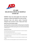
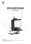
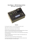
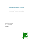
CONTROLS User Manual 1 Contents table 1.- CONTROLS ...................................................................................................................... 3 1.1.- “INTERFACE” SCREEN ....................................................................................................... 3 1.2.- CONNECTIONS .................................................................................................................. 4 1.3.- JOYSTICK........................................................................................................................... 8 1.4.- HANDWHEELS.................................................................................................................. 11 1.5.- PAN BAR (JDR) ............................................................................................................... 16 1.6.- HANDHELD ...................................................................................................................... 23 2 1.- Controls There are four types of control desks for all Scorpio Head. They all have the same “interface” screen, the same control software and the same connections. First of all we are going to define two of these similarities. 1.1.- “interface” Screen The control desk “interface” can be divided into two parts. The first is the display and buttons that are situated around the screen. They are used to interact with the program. The second is the potentiometers situated at the bottom of the screen that are used to define motion variables for the head. Buttons Display Speed control potentiometer (PAN, TILT and ROLL) “0” and direction change button (PAN, TILT and ROLL) 3 1.2.- Connections All of the control desk’s connections are the same. In some cases there are small exceptions which will be show later in this section. VDC 24/30V (Neutrik, 3 pin male) OUT 12V/3A (Neutrik, 4 pin female) HEAD COMMAND (Neutrik, 6 pin female) ROLL HANDWHEEL (Lemo, 5 pin 1B) JDR ROLL (Lemo, 6 pin 1B) JDR ZOOM (Lemo, 6 pin 1B) FIZ COMMAND (Lemo, 7 pin 1B) SERIAL PC 9 pin male connector DB9 ON/OFF switch 4 VDC 24/30V (Neutrik, 3 pin male) 1 VCC IN 30V Red 2 GND Black 3 NC 12V/3A (Neutrik, 4 pin female) 1 GND Black 2 NC 3 NC 4 VCC OUT +12V 3A Red HEAD COMMAND (Neutrik, 6 pin female) 1 NC 2 GND Black 3 NC 4 VCC OUT +30V Red 5 485B Gray 6 485A Pink ROLL HANDWHEEL (Lemo, 5 pin 1B) 1 VCC OUT +5V White 2 GND Brown 3 ENC A ROLL White - Gray 4 ENC B ROLL Yellow - Blue 5 NC 5 JDR ROLL (Lemo, 6 pin 1B) 1 VCC OUT +5V Red 2 GND Black 3 FOCUS Orange 4 ROLL White - Blue 5 IN1 Yellow - Pink 6 IN0 Yellow - Black JDR ZOOM (Lemo, 6 pin 1B) 1 VCC OUT +5V Red 2 GND Black 3 IRIS White - Green 4 ZOOM White - Pink 5 IN2 White - Red 6 IN3 White - Orange FIZ COMMAND (Lemo, 7 pin 1B) 1 VCC OUT +30V Red 2 GND Black 3 485A Yellow - Green 4 485B Yellow - Blue 5 NC 6 NC 7 NC 6 Serial PC 9 pin male connector DB9 1 NC 2 RX 232 Yellow - Red 3 TX 232 Yellow - Brown 4 NC 5 PC GND Green 6 NC 7 NC 8 NC 9 NC All the control desk’s connections are similar except that in some not all of the connectors are use because they are not necessary for functionality of that control: The handwheels have all the connectors The Pan Bar and the Handheld do not have the ROLL HANDWHEEL connector The Joystick control does not have the ROLL HANDWHEEL and JDR ZOOM connectors. 7 1.3.- Joystick The joystick, like the other control desks, allows full control of the head (PAN, TILT and ROLL) and the camera functions: IRIS, FOCUS, ZOOM and zoom speed. Emergency Stop ZOOM speed ZOOM or ROLL Interface screen Joystick (PAN and TILT) ZOOM or ROLL FOCUS 8 The number of controls can be amplified with accessories for eg. the pedal which is connected to the JDR ROLL. Transport case 9 Connections VDC 24/30V (Neutrik, 3 pin male) OUT 12V/3A (Neutrik, 4 pin female) HEAD COMMAND Neutrik, 6 pin female) ROLL HANDWHEEL (NC) JDR ROLL (Lemo, 6 pin 1B) JDR ZOOM (NC) FIZ COMMAND (Lemo, 7 pin 1B) SERIAL PC 9 pin male connector DB9 ON/OFF switch 10 1.4.- Handwheels This control desk has three handwheels which are assigned to the three axes, PAN, TILT and ROLL. In the case that the head is working in two axes it is not necessary to connect the ROLL axis (the Scorpio Stabilized Head is always working in three axes). Monitor support Interface screen ROLL PAN Transport case TILT 11 Connections VDC 24/30V (Neutrik, 3 pin male) OUT 12V/3A (Neutrik, 4 pin female) HEAD COMMAND (Neutrik, 6 pin female) ROLL HANDWHEEL (Lemo, 5 pin 1B) JDR ROLL (Lemo, 6 pin 1B) JDR ZOOM (Lemo, 6 pin 1B) FIZ COMMAND (Lemo, 7 pin 1B) SERIAL PC 9 pin male connector DB9 ON/OFF switch 12 Handwheel mounting First, the Handwheels body is fastened to a Mitchell mount tripod with the included fixation screw. Mitchell mount tripod Fixation screw After that the handwheels are mounted onto the control desk. To mount the handwheels the central screw on the handwheel is fastened to an axis on the handwheels body. Handwheels Tilt axis Fixation screw The tightness or fluidity of the handwheels can be adjusted via a fluid friction system. It is adjusted with the fluid regulator which is situated between each handwheel and the control desk. Fluid regulator 13 In the case when the ROLL axis is used the third handwheel will have to be mounted. Before mounting the actual handwheel, the box with a slide groove (held with a fixation screw) has to be mounted to the control desk body and then the handwheel will be fastened to the box. The ROLL handwheel box fixation screw The slide groove The third handwheel box Lastly, the third axis box is connected to the ROLL HANDWHEEL connector. The complete ROLL axis ROLL axis cable 14 Monitor support To be able to mount the monitor support the “U” shaped bracket must be mounted onto the control desk. The bracket is mounted onto the body via the two slipin supports and fastened with two fixation screws. Slide-in bracket supports The “U” bracket Monitor Base spigot Plastic screw (“U” bracket) Once the “U” bracket has been fixed into place the monitor base can be mounted and fastened onto the monitor base spigot with the fixation screw. Monitor base Plastic screw (monitor base) 15 1.5.- Pan bar (JDR) This control is based on the idea of moving the camera via two arms which are joined by an axis. There is a control on each arm which allows for different camera control functions. Interface screen Monitor support Counter weight Riser JDR ROLL JDR ZOOM ROLL speed ZOOM speed FOCUS Iris ROLL Disengage button Disengage button ZOOM 16 Transport case Connections OUT 12V/3A (Neutrik, 4 pin female) VDC 24/30V (Neutrik, 3 pin male) HEAD COMMAND (Neutrik, 6 pin female) ROLL HANDWHEEL NC ON/OFF switch JDR ROLL (Lemo, 6 pin 1B) JDR ZOOM (Lemo, 6 pin 1B) SERIAL PC 9 pin male connector, DB9 FIZ COMMAND (Lemo, 7 pin 1B) 17 Mounting the control desk As with the Handwheels the body will have to be mounted to a tripod with a Mitchell mount. A riser is mounted on the tripod to avoid bumping the arms against it. Riser Mitchell mount tripod Mounting and connecting the controls First the arms are mounted, with the longer arm on the right hand side (the side on which the fluid adjustments are found). They are attached and fastened with wing nuts onto the axis on the control desk as shown in the image below. Arm axis Left hand arm (short) Arm fixation wing nut 18 Once both the arms have been mounted the controls can then follow. To mount the controls correctly the two wing nuts must be on the inside of the controls (facing each other). Control Wing nut Now, all that is left is to connect the controls to their corresponding connectors. The right hand control will go to the JDR ZOOM connector and the left hand one will go to the JDR ROLL connector. 19 Mounting the counter weight To be able to move the arms as comfortably as possible they have to be counter weighted. It is VERY IMPORTANT that they are completely balanced as to not have unwanted movement with the head and therefore the camera. To balance the arms the safety screw at the end of the long arm is removed. Safety screw Once the safety screw has been removed the counter weight is put onto the arm at the approximate equilibrium point. By turning the black lock-off on the counter weight it is locked in place. Once it has been tightened the balance is checked and if it is not correct the counter weight is adjusted until the perfect balance is achieved. Lock-off 20 Now that the balance is correct the safety screw that was removed in the first step is replaced on the arm. If, for whatever reason, the counter weight had to come loose this safety would stop it from falling off. Safety screw Mounting the monitor support To mount the monitor support the same steps as with the Handwheels have to be followed. First the “U” shaped bracket is mounted into the slide-in supports on the control desk. The plastic screws are used to hold it in place. Then the monitor base is mounted on the spigot on the “U” bracket. The base is then fastened with the plastic screw on the shaft. Monitor base spigot “U” shaped bracket Plastic screw (“U” bracket) Monitor base Plastic screw (monitor base) 21 The fluid systems The fluid system is based on a continuous fluid system which helps to obtain a smooth, constant and controlled movement. It has two fluidity control rings, one for the PAN and one for TILT. These control the counter force of the fluid. Each axis can be locked off with its corresponding brake. TILT brake PAN fluidity control TILT fluidity control PAN brake 22 1.6.- Handheld This control desk has two controls mounted on either side of it. The features of this control are the small size and its ease to move around. Monitor supports Left hand control Active drift Right hand control Interface screen PAN drift ZOOM speed ROLL drift Emergency stop IRIS TILT drift 23 Transport case This case has been made with a space for the monitor. Monitor space Connectors OUT 12V/3A (Neutrik, 4 pin female) VDC 24/30V (Neutrik, 3 pin male) HEAD COMMAND (Neutrik, 6 pin female) ROLL HANDWHEEL NC ON/OFF switch JDR ROLL (Lemo, 6 pin 1B) JDR ZOOM (Lemo, 6 pin 1B) SERIAL PC 9 pin male connector, DB9 FIZ COMMAND (Lemo, 7 pin 1B) 24 The control desk Apart from the common interface screen which all the controls have, this control has some other features. When using a stabilized head each axis’s drift can be corrected. To do this the “drift activate” button is pressed and the potentiometer corresponding to the drifting axis is turned. There are also two more potentiometers: one for the ZOOM speed and another for the IRIS. This control also has an Emergency stop button. It is used if the system is not functioning correctly. Control descriptions The two controls are different. The one has a Joystick for the PAN and TILT on top and another for the ROLL underneath. The other has the Zoom control Joystick on top and a FOCUS control potentiometer below. PAN and TILT ROLL ZOOM FOCUS 25 Mounting the controls To be able to mount the controls the brackets that come with the control desk have to be mounted on both sides of the control desk (as seen below). Once the brackets have been mounted and the bottom screws have been tightened the control position can be adjusted with the top screw. Bracket Position adjustment screw Control fixation screw Once mounted the only thing left to do is to connect them. The control that is responsible for the head’s movement will connect to the JDR ZOOM connector and the control responsible for the lens control will connect to the JDR connector. 26