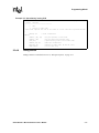
1
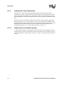
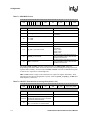
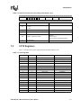
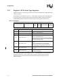
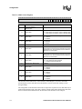
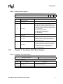
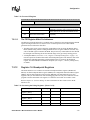
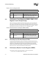
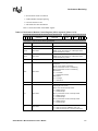
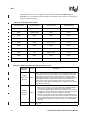
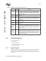
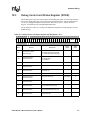
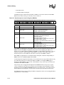
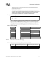
Software Debug
10.3
Debug Control and Status Register (DCSR)
The DCSR register is the main control register for the debug unit. Table 10-3 shows the format of
the register. The DCSR register can be accessed in privileged modes by software running on the
core or by a debugger through the JTAG interface. Refer to Section 10, “SELDCSR JTAG
Register” for details about accessing DCSR through JTAG.
For the Trap bits in Table 10-3 writing a one enables the trap behavior, while writing a zero will
disable the trap.
Table 10-3. Debug Control and Status Register (DCSR) (Sheet 1 of 2)
31 30 29 28 27 26 25 24 23 22 21 20 19 18 17 16 15 14 13 12 11 10
GE H
Bits
TF TI
Access
31
Software Read / Write
JTAG Read-Only
30
Software Read Only
JTAG Read / Write
29:24
TD TA TS TU TR
9
8
7
6
5
4
SA
Description
Global Enable (GE)
3
2
1
MOE
0
M E
Reset
Value
TRST
Value
0
unchanged
unchanged
0
undefined
undefined
unchanged
0
unchanged
0
undefined
undefined
unchanged
0
unchanged
0
unchanged
0
unchanged
0
unchanged
0
0: disables all debug functionality
1: enables all debug functionality
Halt Mode (H)
0: Monitor Mode
1: Halt Mode
Read-undefined / Write-As-Zero
Reserved
23
Software Read Only
JTAG Read / Write
Trap FIQ (TF)
22
Software Read Only
JTAG Read / Write
Trap IRQ (TI)
21
Read-undefined / Write-As-Zero
Reserved
20
Software Read Only
JTAG Read / Write
Trap Data Abort (TD)
19
Software Read Only
JTAG Read / Write
Trap Prefetch Abort (TA)
18
Software Read Only
JTAG Read / Write
Trap Software Interrupt (TS)
17
Software Read Only
JTAG Read / Write
Trap Undefined Instruction (TU)
16
Software Read Only
JTAG Read / Write
Trap Reset (TR)
Intel® XScale™ Microarchitecture User’s Manual
10-3